ABSTRACT
A simplified model of natural convection, similar to the Lorenz system, is compared to computational fluid dynamics simulations of a thermosyphon in order to test data assimilation (DA) methods and better understand the dynamics of convection. The thermosyphon is represented by a long time flow simulation, which serves as a reference ‘truth’. Forecasts are then made using the Lorenz-like model and synchronised to noisy and limited observations of the truth using DA. The resulting analysis is observed to infer dynamics absent from the model when using short assimilation windows. Furthermore, chaotic flow reversal occurrence and residency times in each rotational state are forecast using analysis data. Flow reversals have been successfully forecast in the related Lorenz system, as part of a perfect model experiment, but never in the presence of significant model error or unobserved variables. Finally, we provide new details concerning the fluid dynamical processes present in the thermosyphon during these flow reversals.
1. Introduction
Forecasting methodologies, traditionally motivated by numerical weather prediction (NWP), can find applications in other fields such as engineering (Savely et al., Citation1972), finance (Sornette and Zhou, Citation2006; Bollen et al., Citation2011), epidemiology (Ginsberg et al., Citation2009) and marketing (Asur and Huberman, Citation2010). Techniques borrowed from the weather forecasting community may prove to be powerful for forecasting the other types of complex systems. Fluid systems can be particularly challenging due to dynamics taking place at multiple interacting spatial and temporal scales. However, because of their relationship to NWP, fluid systems are among the most studied in the context of forecasting.
In this study, we show that the flow in a computational fluid dynamics (CFD) simulated thermosyphon undergoing chaotic convection can be accurately forecast using an ordinary differential equation (ODE) model akin to the classic Lorenz (Citation1963) system. The thermosyphon, a type of natural convection loop or non-mechanical heat pump, can be likened to a toy model of climate. Thermosyphons are used in solar water heaters (Belessiotis and Mathioulakis, Citation2002), cooling systems for computers (Beitelmal and Patel, Citation2002), roads and railways that cross permafrost (Lustgarten, Citation2006), nuclear power plants (Detman and Whipp, Citation1968; Beine et al., Citation1992; Kwant and Boardman, Citation1992) and other industrial applications. In these heat pumps, buoyant forces move fluid through a closed loop, and at high amounts of forcing they can exhibit complex aperiodic behaviour. As first suggested by Lorenz (Citation1963), this is illustrative of the unpredictable convection behaviour observed in weather and climate dynamics.
Synthetic observations of the thermosyphon are combined with model data to produce new forecasts in the process known as data assimilation (DA). DA is a generic method of combining observations with past forecasts to produce the analysis, an approximately optimal initial condition (IC) for the next forecast cycle. Another interpretation of the analysis is that it is a ‘best guess’ for the true system state as represented in the phase space of the model. DA can be used as a platform for the reanalysis of past observations, in which the dynamical model plays a key role in constraining the state estimates to be physically realistic (Compo et al., Citation2006).
In the present study, we use an analysis of simulated thermosyphon mass flow rate data to explain the heat transport processes occurring during chaotic flow reversals and to inform empirical forecasts of the occurrence of these flow reversals. Although the flow reversals are chaotic, we show they have short-term predictability, quantifying the extent to which this is possible with our methods.
This paper is structured in the following way: in Section 2, we explain the CFD simulation used to generate a synthetic true state or ‘nature run’ of the thermosyphon and the separate forecasting model. In Section 3, we present an overview of how DA was applied to this experiment and its performance. In Section 4, we explain and present the results for flow reversal and rotational state residency time forecasts. Finally, Section 5 contains concluding remarks. In Appendices S1-4 in the Supporting Information, we present a derivation of the model, detail the tuning of model parameters and explain in detail the DA methods used.
2. Models and the DA algorithm
Following previous experiments that examined the periodic (Keller, Citation1966) and chaotic (Welander, Citation1967; Creveling et al., Citation1975; Gorman and Widmann, Citation1984; Gorman et al., Citation1986; Ehrhard and Müller, Citation1990; Yuen and Bau, Citation1999; Jiang and Shoji, Citation2003; Burroughs et al., Citation2005; Desrayaud et al., Citation2006; Yang et al., Citation2006; Ridouane et al., Citation2009) behaviour of toroidal thermosyphons, we also consider a circular thermosyphon geometry. Picture a vertically oriented hula hoop, as shown in . An imposed wall temperature T
h on the lower half of the loop heats the fluid contained in this section. Similarly, a wall temperature
is imposed on the upper half
to cool the upper section (). The forcing, proportional to the temperature difference
, is constant. We focus on the case of developed flow, ignoring transient behaviour.
Fig. 1. The thermosyphon has a simple circular geometry. The bottom wall is heated to a constant hot temperature T
h while the top wall is maintained at the temperature T
c, creating a temperature inversion of hot fluid below cold fluid. If conduction alone cannot stabilise this temperature inversion, then the fluid will begin to rotate and convection becomes the dominant process of heat transfer. The relevant model state variables are proportional to the bulk fluid velocity u and the temperature difference across the loop . For CCW flow, as indicated by the arrow near 9 o'clock, fluid velocity
and
is typically >0. The radius ratio
used in our experiments is shown to scale.
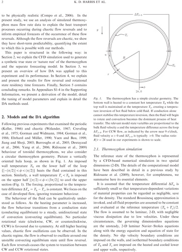
The behaviour of the fluid can be qualitatively understood as follows. As the heating parameter is increased, the flow behaviour transitions from a conduction state (conducting equilibrium) to a steady, unidirectional state of convection (convecting equilibrium). No particular rotational state (clockwise, CW, or counterclockwise, CCW) is favoured due to symmetry. At still higher heating values, chaotic flow oscillations can be observed. In the chaotic regime, the flow is observed to oscillate around one unstable convecting equilibrium state until flow reversal. Each flow reversals causes the system to transition between CW and CCW rotational states.
2.1. Thermosyphon simulation
The reference state of the thermosyphon is represented by a CFD-based numerical simulation in two spatial dimensions (2-D). The details of the computational model have been described in detail in a previous study by Ridouane et al. (Citation2009); however, for completeness, we summarise here its essential elements.
It is assumed that the temperature differential is sufficiently small so that temperature-dependent variations of material properties can be regarded as negligible, save for the density. The standard Boussinesq approximation is invoked, and all fluid properties are assumed to be constant and evaluated at the reference temperature
. The flow is assumed to be laminar, 2-D, with negligible viscous dissipation due to low velocities. Under these circumstances, the governing dimensionless equations are the unsteady, 2-D laminar Navier–Stokes equations along with the energy equation and equation of state for the density. No slip velocity boundary conditions are imposed on the walls, and isothermal boundary conditions of T
h and T
c are imposed on the heated and cooled lower and upper walls, respectively.
The dimensionless control parameter for convection is the Rayleigh number, defined here as1
where g is the gravitational acceleration, is the thermal expansion coefficient, v is the kinematic viscosity and κ is the thermal diffusivity.
The one dimensionless geometric parameter is the ratio of major (loop) radius R to minor (tube) radius r, hereafter referred to as the radius ratio. Consistent with the previous study, the dimensions of the loop are chosen with R=36 cm and r=1.5 cm to yield a radius ratio of 24.
As in the classic Rayleigh–Bénard problem, the Rayleigh number determines the onset of convection in the thermosyphon. For the numerical simulations on this fixed geometry, a range of Rayleigh numbers can be imposed by varying the value of the gravitational acceleration. As the Rayleigh number is increased from 0, the flow behaviour transitions from a stationary, conduction state to a steady, unidirectional state of convection. At still higher values of Ra, chaotic flow oscillations can be observed. Unless otherwise indicated, the simulation results presented in this paper correspond to a value of Ra = 1.5×10⁵, which is within the chaotic regime.
All numerical simulations were performed using the commercial CFD software ANSYS Fluent (Citation2006), which is based on the finite-volume method. (An example of the output is shown in , in the discussion of flow reversals.) During the course of the simulations, the time-varying mass flow rate, a scalar denoted by q and proportional to u, is saved at 10 s intervals. This reporting interval is conservative, as laboratory thermocouples can be sampled more than once per second. In doing so, a timeseries of the ‘true’ synthetic thermosyphon state is recorded to be used in a forecasting scheme.
2.2. Forecast model
The Ehrhard–Müller (EM) system is a three-variable ODE derived specifically to model bulk flow in the thermosyphon (Ehrhard and Müller, Citation1990; also see Appendix S1 in the Supporting Information for an alternative derivation). Written in dimensionless form, the governing equations are2a
2b
2c
The state variable x
1 is proportional to the mass flow rate or mean fluid velocity, x
2 to the temperature difference across the convection cell (, measured between 3 and 9 o'clock) and x
3 to the deviation of the vertical temperature profile from the value it takes during conduction; specifically,
, where
is the temperature difference measured between 6 and 12 o'clock. The parameter α is comparable to the Prandtl number, the ratio of momentum diffusivity and thermal diffusivity. Similar to the Rayleigh number, the heating parameter
determines the onset of convection as well as the transition to the chaotic regime. Finally, K determines the magnitude of variation of the wall heat transfer coefficient with velocity. The functional form of that variation is determined by
, where
3
The interested reader is referred to Appendix S1 in the Supporting Information for an explanation of this piecewise form, which differs slightly from the original model of Ehrhard and Müller (Citation1990).
Note that when K=0, the system is analogous to the Lorenz (Citation1963) system, with geometric factor (Lorenz's b) equal to 1. The lack of a geometric factor in the EM system is due to the circular geometry of the convection cell. Lorenz equations have been widely used in non-linear dynamics to study chaos and in NWP as a model system for testing DA (Miller and Ghil, Citation1994; Yuen and Bau, Citation1999; Annan and Hargreaves, Citation2004; Evans et al., Citation2004; Yang et al., Citation2006; Kalnay et al., Citation2007).
When in the chaotic parameter regime, the EM system exhibits growing oscillations in the x
1 and x
2 state variables around their convecting equilibrium values until flow reversal. In this system, the CCW rotational state is characterised by and
, and the CW rotational state by
and
. However, one should note that near a flow reversal x
1 and x
2 can have opposite signs, because zero-crossings of the x
1 variable typically lag behind those of x
2.
The parameters found to match the simulated thermosyphon were ,
and
. The characteristic time and mass flow rate scales, used to transform the dimensionless model variables
and x
1 into dimensional time and ‘observations’ of mass flow rate, were 631.6 s and 0.0136 kg s−1, respectively. The q scale is the one non-zero entry in the observation operator H, eq. (4). The above parameters were found using a multiple shooting algorithm explained in Appendix S1.2 in the Supporting Information. Numerical integration of this autonomous ODE was performed with a fourth-order Runge–Kutta method and timestep 0.01 (corresponding to 6.316 s) in Matlab (Citation2009).
2.3. Data assimilation
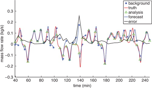
Data assimilation is the process by which observations of a dynamical system are combined with forecasts from a model to estimate error co-variances and calculate an optimal estimate for the current state of the system, called the analysis. The inherent difficulties are compounded by the fact that the forecaster uses an inexact forecasting model and never knows the true state of the dynamical system. The number of state variables in an NWP model is typically times larger than the number of observations. Nevertheless, the analysis becomes the IC for a new forecast. The time interval between successive applications of the DA algorithm, that is the time between analysis steps (usually determined by the availability of observations but here allowed to vary), is called the assimilation window. The process is shown in .
Fig. 2. An illustration of the basic predict-observe-update DA cycle. The EM model states (background forecast and analysis) are transformed into observations of the mass flow rate q by the observation operator [eq. (4)] for comparison with the truth. Here, using the 3-D-Var algorithm and an assimilation window of 5 min, the filter has satisfactory overall performance (scaled error≈35%). Note the error spike around 135 min when the forecast and truth end up in different rotational states. The largest errors tend to occur at or near flow reversals due to inherent sensitivity near that transition and to the qualitatively different behaviour of the different flow directions.
A variety of filters are capable of solving the DA problem. The canonical example is the Kalman filter (KF; Kalman, Citation1960), the optimal state estimation algorithm for a linear system. One of DA's first applications was to trajectory estimation and correction of missiles and rockets (Savely et al., Citation1972). A number of non-linear DA schemes are implemented in this study. In 3-D variational DA (3-D-Var; here 3-D refers to the spatial dimensions for weather models), the background error covariance is estimated a single time, offline, prior to the DA procedure. In the extended Kalman filter (EKF), background error is evolved according to the linear tangent model, which approximates the evolution of small perturbations about the trajectory. Ensemble Kalman filters (collectively EnKFs) use ensembles of forecasts to estimate the background error and better capture non-linear behaviour. The methods examined in this study were 3-D-Var, the EKF, the ensemble square root Kalman filter (EnSRF) and the ensemble transform Kalman filter (ETKF). Detailed descriptions of each method are included in Appendix S2 in the Supporting Information. A full review of DA is beyond the scope of the present paper; for a comprehensive treatment, we refer the reader to Kalnay (Citation2002).
3. Data assimilation experiments
3.1. Methods
A perfect model experiment, in which the Lorenz equations were used to forecast a synthetic truth created by the exact same system, was tested first but not included here. We found analysis errors similar to those reported by Yang et al. (Citation2006) (3-D-Var and EKF) and Kalnay et al. (Citation2007) (ETKF), using the same model and tuning parameters. This ensured that the DA algorithms were working before applying them to the synthetic thermosyphon data.
As stated in Section 2.1, forecasts of the thermosyphon are made observing one scalar variable, the mass flow rate . Gaussian noise with SD equal to 6×10⁻⁴ kg s−1, approximately 0.8% of the mass flow rate climatological mean,
, is added to the synthetic truth to create observations. The relative magnitude of this error is comparable to that of experimental measurements.
The EM model is used in the forecast step to integrate the analysis forward in time and create the new background forecast. The end results of applying DA are a background and analysis timeseries of , informed by both the timeseries of thermosyphon mass flow rate and the EM model dynamics.
In this realistic forecasting scenario, where only limited information about the true state is available, the observations of state variable q provide the only validation. For this reason, we calculate the forecast errors in observation space. These are given as root mean square error (RMSE), where . The residual at a specific assimilation cycle is given by
. Here,
is the background forecast made by the model, and
is the linear observation operator
4
in units of kilogram per second. All errors are then scaled by , the climatology of q. Analysis error is a common metric for assessing DA performance in perfect model experiments. In this study, however, we assert that background error is preferable. Analysis error in observation space, which will be small even for large assimilation windows, is not an appropriate metric for assessing model performance since it can disagree substantially with the background error. For example, 3-D-Var in one experiment with a 10-min assimilation window yielded analysis and background scaled errors of 0.08 and 0.86, respectively. The analysis error would seem to indicate that forecasting is doing a good job, but the background error shows that background forecasts are essentially meaningless. The filter, however, accounts for this and weights the observations heavily over the background forecasts when producing the analysis. Since we are concerned with forecasting, background error is a more representative metric.
When applying DA to non-linear systems, some type of covariance inflation is performed to prevent filter divergence due to error underestimation. Kalnay et al. (Citation2007) found that a Lorenz forecasting model with a slightly different forcing parameter required a 10-fold increase in the multiplicative inflation factor when using a three-member EnKF. Model error is more pronounced for our forecasts, since the EM model is a reduced approximation of the numerically simulated thermosyphon. We relied upon additive and multiplicative background covariance inflation to capture model error. Additive inflation was particularly important for the stability of the EKF and EnKFs. Additive noise provides a different exploration of dynamically accessible regions of state space, and it would be interesting to explore why additive versus multiplicative is preferred in certain cases, although this is beyond the scope of this paper. The specifics of how inflation was performed and tuned, and the parameters used are given in Appendix S2 in the Supporting Information.
All EM and DA parameter tuning was performed using a separate mass flow rate timeseries than was used for validation. Each DA algorithm was allowed 500 cycles to spin up, and its performance was measured over the following 2500 cycles. Ensemble size in each case was set to 10 members.
3.2. Results
With proper tuning, all DA algorithms were capable of synchronising the EM model to observations of mass flow rate alone. As the assimilation window increased, scaled background error increased in a sigmoidal fashion, as expected (see ). For assimilation windows up to 2.5 min, all DA algorithms have nearly indistinguishable errors. For assimilation windows between 3 and 6 min, 3-D-Var performs noticeably worse than the other methods, which remain indistinguishable. Then, with assimilation windows greater than 6 min, the ensemble methods (EnSRF and ETKF) outperform the EKF noticeably. This is perhaps surprising, at first glance, because the ensemble size is significantly smaller than the dimension of the simulated thermosyphon state space [ variables]. However, we know that the thermosyphon dynamics effectively take place on the EM equations’ attractor (a manifold in three dimensions). The superior performance of EnKFs here is likely due to the ensemble methods capturing non-linear effects that dominate at larger windows.
Fig. 3. Background RMSE scaled by over 2500 assimilation cycles plotted for different DA algorithms and varying assimilation windows. As the window becomes larger, the error increases towards saturation. The lower dashed line in the main figure shows the limit of a ‘perfect’ forecast while the upper demarcates a ‘useless’ forecast.
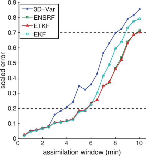
Following the historical S1 score convention, scaled error above 70% is considered a ‘useless’ forecast while under 20% the forecast is ‘perfect’ (Kalnay, Citation2002). Perfect forecasts for 3-D-Var were found up to a 4-min assimilation window while the other methods (EnSRF, ETKF and EKF) produced perfect forecasts with assimilation windows 1.5 min longer.
A persistent spike in background error for the 5-min assimilation window () is possibly due to that time being approximately the same as the characteristic period of oscillations in q (evident in ). We conjecture that this may lead to a type of resonance in the DA-coupled EM system, which degrades the DA performance.
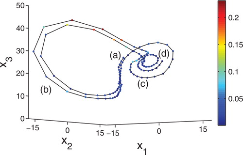
Besides these results pertaining to forecast skill, we also found that the DA algorithms infer thermosyphon dynamics which are absent from the EM model. In , we show the simulated thermosyphon's attractor obtained by both a time-delay embedding (a; Alligood et al., Citation1996) and a projection of the EM analysis states to the x 1−x 2 plane (b). If the thermosyphon fluid flow stalls in the midst of a reversal, fluid in the bottom can quickly heat up while that in the top is cooled, leading to an unstable, strong temperature inversion. This causes the fluid to move very quickly in the reversed direction, but this new direction also ends up being unstable, and a new flow reversal can occur immediately. Absent DA, the EM model system does not exhibit this behaviour of stalling followed by large swings of the trajectory.
Fig. 4. Two views of the numerically simulated thermosyphon attractor. A time-delay reconstruction, using the monitored mass flow rate, is shown in (a). In (b), plotted points show x 1 and x 2 of the EM analysis generated by EKF with an assimilation window of 120 s. Each is coloured by the scaled background forecast error at that point. The delay time of 60 s used for (a) was chosen because it yielded a good approximation of the attractor in (b). Note how in (a) trajectories that move through the far edge of either lobe create distinctive loops near the centre of the opposite lobe. This is an example of dynamics which are not present in the EM model without DA. It may explain the higher error for points in (b) at the far edge of each attractor lobe. See text for further description and for another example.
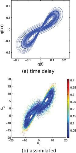
In the time-delay embedding (a), this phenomenon is exhibited by small loops in the trajectory as it moves near the convective fixed points. The flow stalls when the system state is near the conductive fixed point at the origin, then it swings wildly, which brings it near the convective fixed point, but in such a way that it does not end up spiraling outward in the usual fashion as during a normal flow reversal, as exhibited by the Lorenz equations. Instead, it quickly reverses again, which we call non-Lorenz behaviour. This non-Lorenz behaviour is further elaborated upon in Section 4.5. Forecast skill is worst at the far edges of the assimilated attractor (b). This could be due to the wild swings of the EM trajectory after being ejected from the region of state space near the conducting equilibrium, or to the non-linear dynamical instabilities at the edge of the attractor found by Palmer (Citation1993) and Evans et al. (Citation2004).
We also explicitly show one of these stalled flow reversals in , where we plot the EKF-assimilated EM trajectory using a 30 s assimilation window. When the fluid stalls, the x
3 variable moves closer to 0 (i.e. increases) while x
1 and x
2 (proportional to q and
, respectively) are approximately 0, reflecting the growing temperature inversion while the fluid remains stationary. When the fluid starts to move, the assimilated trajectory swings wildly to the left attractor lobe (CW rotational state) and then right (CCW rotational state). The trajectory undergoes another stall-swing cycle before finally resuming Lorenz behaviour, where the trajectory spirals outward from the CCW convecting equilibria. This contrasts the Lorenz and EM model dynamics, for which large deviations in the system state from convecting equilibrium are driven close to the other convecting equilibrium during a flow reversal, which stabilises the system (see also Section 4.5, and the accompanying discussion). This result remains unchanged for the other DA algorithms also using a 30 s assimilation window. The inference remains using EKF and a 60 s assimilation window, but the trajectory appears much noisier, leading us to believe that this is due to the rapid update. With larger assimilation windows, the trajectory becomes uninterpretable as error in the unobserved variables increases.
Fig. 5. The assimilated trajectory during a very large oscillation, non-Lorenz flow reversal. The EKF algorithm with a 30 s assimilation window was used. Colour indicates the scaled background error. The state starts (a) in the CCW rotational region and stalls near the conducting state for an extended period, causing fluid in the bottom to heat up, manifesting in an x 3 that creeps towards 0 with x 1, x 2≈0, before the state swings quickly (b) through one oscillation in the CW rotational state. This is followed by one oscillation in the CCW state (c) before another stall near the conducting point and subsequent swing (b again) before settling into Lorenz-like oscillations (d). Note that the filter only observes the x 1 variable but is able to reconstruct the dynamics in the full state space.
4. Flow reversal experiments
4.1. Experimental setup
For the purpose of flow reversal forecasts, we picked a single DA algorithm and assimilation window. In this section, all analyses were generated by the extended KF and an assimilation window of 30 s. This interval corresponds to five time steps of the model and is shorter than that used in Yang et al. (Citation2006) and Kalnay et al. (Citation2007). The following could certainly be repeated using other algorithms, observations and assimilation windows, but this was beyond the scope of this paper. The flow reversal tests in Section 4.3 and the residency time forecasts in Section 4.4 were tuned and validated on separate analysis timeseries. The length of the tuning and validation timeseries were approximately 39 and 93 d, respectively.
4.2. Occurrence of flow reversals: traditional explanation
The first explanation of the mechanism responsible for flow reversals was presented by Welander (Citation1967) and repeated by Creveling et al. (Citation1975). Welander, who was also the first to discover that thermosyphons exhibit aperiodic oscillatory behaviour, explained the instability of steady convecting flow by considering a thermal anomaly or ‘warm pocket’ of fluid. For low heating rates, the convecting equilibrium is stable because viscous and thermal dissipation are in phase, thus an increase (decrease) in flow rate leads to an increase (decrease) in friction and a decrease (increase) in buoyancy, and such perturbations are damped out. At higher heating rates, the warm pocket is amplified with each cycle through the loop due to out of phase viscous and thermal dissipations. Welander explained that when the warm pocket emerges from the heating section and enters the cooling section, it feels a greater buoyant force than the surrounding fluid and accelerates, exiting the cooling section quickly, giving it less time to radiate away its energy. As the pocket moves into the section with warm boundary, the buoyant force it experiences is again higher than normal, so now the pocket decelerates and passes slowly through the heating section, gaining more energy. This positive feedback effect causes the pocket to grow hotter and larger with each pass through the loop. These oscillations in the fluid temperature and velocity do not grow unhindered, however. The pocket eventually becomes large and hot enough that its descent towards the heating section is stopped entirely by its own buoyancy. Without movement, the pocket dissipates, but its remnant heat biases new rotation in the opposite direction, and the flow reverses.
In the Lorenz and EM systems, this feedback is embodied in the spiraling repulsion of trajectories from the unstable convecting equilibria at the centre of each lobe or wing of the attractor before moving to the other lobe. Because the growth of oscillations is an important component to the flow reversal process in both the CFD simulated thermosyphon and EM system, we define here what is meant by oscillation amplitude in each case. In the CFD simulated thermosyphon, it is the maximum distance of the system state from the nearest convecting equilibrium, where system state is understood to mean the state of the entire temperature and velocity flow fields in the CFD simulation. When considering the DA-generated EM analysis, the kth x
1 oscillation amplitude is defined as the maximum amplitude
5
where is the time interval of the kth oscillation.
4.3. Flow reversal forecasting methods
Three separate tests were developed to predict, at each assimilation step, whether a flow reversal would occur within the next oscillation period (approximately 11 min), here taken to be within the next 20 DA cycles. See Section 4.6 and Appendix S3 in the Supporting Information for a description of how the tunable parameters were chosen.
4.3.1. Lead forecast.
The simplest test forecasts a flow reversal whenever the background forecast changes rotational state. Note that to forecast a flow reversal occurring in the future, the background forecast started from the most recent analysis IC provides our only information about the system's future state. Ignoring the 3-D nature of the state space, a flow reversal is forecast whenever x
1 crosses through zero. Note also that the forecast is unable to predict flow reversals that occur beyond the lead time, and that lead forecast quality quickly degrades as the lead time is increased. We impose a limit on the number of assimilation cycles to look ahead, , so that the algorithm does not trust forecasts too far in advance.
4.3.2. Bred vectors.
An ensemble of perturbed states forming a small ball around the analysis can be used to represent uncertainty in the IC. A non-linear system will dynamically stretch and shrink such a ball around its trajectory as it moves through the attractor (Danforth and Yorke, Citation2006). Small perturbations to points on a trajectory are integrated forward in time, and the differences between perturbed and unperturbed solutions are called bred vectors (BVs). Here, the rescaling amplitude is 0.001, and the integration time coincides with the 30 s assimilation window.
The average BV growth rate is a useful measure of local instabilities (Hoffman et al., Citation2009). Evans et al. (Citation2004), studying perfect-model forecasting of the Lorenz system, set a BV growth rate threshold that accounted for 91.4% of the observed flow reversals (hit rate). Our BV test simply forecasts a flow reversal whenever the average BV growth rate over the previous assimilation window exceeds a threshold, .
4.3.3. Correlation.
The final test uses the fact that flow reversals are suspected to be caused by out of phase viscous and thermal dissipation. Since the friction term grows with fluid velocity and the thermal dissipation grows with the size of the temperature anomaly, related to x
2, we examined the correlation between those two variables over a tunable number of previous analysis cycles. Specifically, when the slope of the least-squares linear fit of
previous analysis points
for
exceeds a threshold
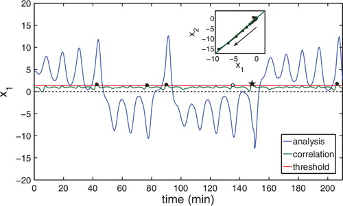
, a flow reversal is forecast (see for an illustration of this process). Interestingly, increasing autocorrelation of the state seems to be a universal property of many systems in advance of critical transitions (Scheffer et al., Citation2009; Hines et al., Citation2012).
Fig. 6. Correlation test: whenever the slope (green) of the correlation exceeds a threshold (red), a flow reversal is forecast. Correct positive predictions are shown as filled circles and false positives as open circles. The starred point corresponds to the inset, which shows how correlation is computed as the slope of the least squares fit (green line) of previous analysis points, and the arrow shows the direction of the trajectory. Note that each analysis cycle where the correlation fails to exceed the threshold counts as a correct negative forecast (not shown). There are no false negatives, that is misses, in this timeseries. Here,
and
are the same as for .
4.4. Forecasting residency times in the new rotational state
We found that the analysis’ x 1 oscillation amplitude preceding each flow reversal is correlated with the duration of the following rotational state, as shown in . We refer to these durations between flow reversals as residency times. Residency times are observed at discernible ‘steps’ corresponding to integer numbers of oscillations. This correlation makes the x 1 oscillation amplitude a plausible predictor for residency time in the new rotational state.
Fig. 7. Residency time in the new rotational state is plotted versus the amplitude of x
1 (proportional to the mass flow rate) at the last extremum before flow reversal. This amplitude is calculated from the EM model EKF analysis of thermosyphon observations, using a 30 s assimilation window. This figure contains over 39 d of simulated flow and 1796 flow reversals. Points are coloured by the average BV growth rate over the preceding assimilation window, showing a BV growth rate gradient that increases in the positive direction along both axes. Inset, upper left: a timeseries corresponding to a single point in the scatter plot, marked with a black cross. The x
1 oscillation amplitude and subsequent residency time are denoted by the vertical and horizontal arrows, respectively. Inset, upper right: a histogram showing the likelihood of residency times following an . This is the interval that we would consider for an x
1 oscillation amplitude of 10.5 preceding flow reversal. The most likely residency time is about 23 min or two oscillations, the middle ‘step’ for the histogram range.
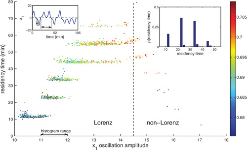
Furthermore, the average BV growth rate measured over the assimilation window preceding that extremum follows a clear gradient in , the growth rate increasing with oscillation amplitude. The BV growth rate gradient implies that more unstable system states precede longer residency times in the next rotational state. Outliers with result in shorter residency times than expected from making similar plots to for the pure Lorenz and EM systems (not shown). In the Lorenz and EM systems, the steps continue to move upwards with x
1 oscillation amplitude. The discrepancy is due to the non-Lorenz behaviour that was mentioned at the end of Section 3.2.
Our residency time prediction algorithm proceeds as follows. When a flow reversal is forecast by one of the methods described in Section 4.3, the algorithm first calculates as defined by eq. (5) for the presently occurring oscillation. The algorithm uses only the analysis and lead forecast data available at the time the flow reversal test is triggered when estimating
. The algorithm then examines the residency times of all flow reversals, which followed an
in the interval
. These ordered pairs of amplitudes and residency times are drawn from the training timeseries. From the relative abundance of residency times in this sample, we assign a probability to the number of flow oscillations in the forthcoming rotational state (see the inset histogram in ). The categories are restricted to one to six oscillations (a duration of seven oscillations, as shown in , is observed exactly once in the training timeseries, so it was considered too rare an event to merit a category). The typical residency times corresponding to one, two, three, four, five and six oscillations are taken to be 11.48, 23.09, 33.72, 44.38, 55.11 and 66.08 min, respectively; the oscillation category associated with a given residency time is taken to be that with the closest time in this list. This algorithm generates a probabilistic forecast from the relative abundance of points in each oscillation category. An example output would be 20, 40, 30 and 10% chance of one, two, three and four oscillations in the next rotational state and zero probability of five or six oscillations.
4.5. New details regarding the flow reversal mechanism
Not all flow reversals occur when the system reaches the same flow oscillation amplitude, nor do all rotational states last the same amount of time. During a flow reversal, the fluid motion stalls after hot fluid extends across the entire heating section into the cooling section (see Section 4.2 and ). The magnitudes of this hot ‘tongue’ and, likewise, the opposite cold tongue affect the stability of the system as it reverses. If the oscillation is small, it will mostly dissipate before the new rotational state is entered, bringing the temperature profile close to that of conduction. This is a highly unstable equilibrium, since the vertical temperature gradient builds until the fluid in the bottom is much hotter than the fluid above (illustrated in the analysis in ). When the fluid begins to rotate, it accelerates rapidly. The large amount of heat carried by the fluid brings the system state far from the convecting equilibrium. If the oscillation is large (corresponding to a large deviation from convecting equilibrium in temperature and velocity), remnant warm and cool areas will be present in the top and bottom sections of the loop, respectively. These stabilise the new rotational state near its convective equilibrium. The resulting duration is longer since the instability requires more time to grow before causing the next reversal. These two situations are shown in and explain the trend in the Lorenz region of . Animations of the simulated temperature field during flow reversal are consistent with this explanation. A movie similar to the case shown in is provided as supplementary material and may also be found online at http://www.uvm.edu/~kharris/thermosyphon/T-Ra-18000-new.mp4.
Fig. 8. Temperature profiles before and after two flow reversals for the chaotic regime in units of Kelvin. For ease of visualisation, the radius ratio is reduced to 3 (). The amplitude of the oscillation shown in (a) is relatively weak; the temperature profile quickly approaches (b) that of conduction (c) where it heats up significantly before the reversal. The extreme instability of the conducting state, near time 20 min, produces a large oscillation in the CW direction (d), immediately causing another flow reversal back to CCW. As the system enters the new rotational state, remnant heat stabilises the flow [contrast (e − f) with (b − c)], necessitating a longer residency in the new rotational state while the instability grows (g − i) (note that for the radius ratio of 24 no more than seven oscillations are ever observed).
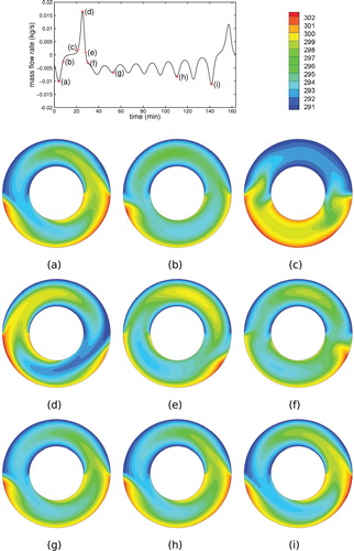
We believe that the behaviour in the extremely large oscillation, non-Lorenz region, where and shown in , is caused by excessive remnant thermal energy after flow reversal. Although the temperature distribution present after a flow reversal is configured in a way that stabilises the flow in the new rotational state, the very large magnitude of the temperature field is a competing, destabilising factor that dominates as
increases into the non-Lorenz region. This leads to shorter durations in the new rotational state before a second flow reversal occurs.
4.6. Flow reversal forecast skill
The results of the three tests are shown in as two-by-two contingency tables. shows the threat score (TS), false alarm ratio (FAR) and probability of detection (POD) (Wilks, Citation1995). Given a non-probabilistic yes/no forecast with a hits, b false alarms, c misses and d correct negatives for a total of n events, these are defined as ,
,
. Because flow reversals are relatively rare events, the hit rate
would be dominated by correct negatives. Instead, TS is chosen as an appropriate overall performance metric since it disregards these frequent negative events and takes into account both false alarms and misses.
Table 1. Contingency tables for the three flow reversal tests
Table 2. Skill scores for flow reversal categorical forecasts (TS, FAR and POD) and residency time probabilistic forecasts (RPS-avg and RPS-med) for the three tests
There are trade-offs among the various skill scores for each flow reversal test. Tuning the reversal tests then amounts to multiobjective optimisation, attempting to maximise TS, RPS-avg and RPS-med (the skill scores used for residency time forecasts, defined in Section 4.7), minimise FAR and maintain POD above 95%. The goal was to tune each method to all-around good performance, for both reversal occurrence and residency time forecasts. To guide the process, plots of the skill scores were made for different tuning parameters, but the final tuning was performed ad hoc. In Appendix S3 in the Supporting Information, Fig. S3-2 shows one of these tuning experiments, with the final parameters chosen appearing in the centre of each subfigure.
Considering TS alone, the lead forecast performed best, followed by the correlation test, with the BV test performing poorest. The BV test also had a very high FAR, leading us to conclude, in contrast to the results of Evans et al. (Citation2004) for a perfect model experiment, that BV growth rate is a poor overall predictor of flow reversals in a realistic thermosyphon. On the other hand, the correlation test had the lowest FAR while maintaining a high TS, but this comes at the price of more misses, resulting in a lower POD. The reasonable performance of the correlation test in all areas lends circumstantial evidence to the claim that out of phase dissipations are indeed the cause of flow reversals.
The flow reversal occurrence tests are triggered in different situations, leading to variation in how far in advance flow reversals are detected, the ‘warning time’. Warning times were only computed for hits, that is forecast flow reversals that were observed to occur. The lead, BV and correlation tests had average warning times of 175, 217 and 304 s, respectively. Histograms of these warning times are presented in Appendix S3 in the Supporting Information.
4.7. Residency time forecast skill
A näive way of forecasting residency times would assign each possible outcome a probability equal to that measured from the climatology. In our case, this would amount to using the marginal distribution of oscillation occurrence. However, our method also takes into account the before the flow reversal (i.e. the joint distribution of events by oscillation occurrence and
), which we have shown contains important information about the number of oscillations that the system will undergo in the new rotational state. Therefore, we compare our method to climatology using a ranked probability skill score (RPS, see Wilks, Citation1995). This is only computed in the case of hits. We actually computed two variants, by taking either the mean (RPS-avg) or median (RPS-med) of the ranked probability scores for each reversal event when computing the skill. The results are shown in . The lead forecast test performs best, followed by the BV test and the correlation test. Unsurprisingly, the flow reversal tests with smaller warning times performed better when making residency time forecasts. Because there is more information about the system state immediately preceding a flow reversal if the warning time is small, the residency time forecast is better informed. The magnitude of the improvement over climatology is large for all methods. The RPS scores in are similar to or better than those for probabilistic forecasts in NWP (Doblas-Reyes et al., Citation2000; Tippett and Barnston, Citation2008).
5. Conclusion
Data assimilation was shown to be an effective way of coupling a simplified model to CFD simulations of the thermosyphon. Although background forecast errors were always larger than observational noise, climatically scaled background error was small for reasonable assimilation windows. Proper tuning of multiplicative and additive inflation factors was essential for avoiding filter divergence and achieving low forecast error. All of the DA methods used in this study accurately capture the behaviour of the thermosyphon with short assimilation windows. Among the DA methods, the ensemble methods show advantages over 3-D-Var and EKF with longer assimilation windows, when non-linear error growth becomes important. With frequent analysis update, DA can reveal non-Lorenz behaviour in the thermosyphon even with the EM (Lorenz-like) model.
Three different predictors of flow reversals were proposed and tested with reasonable success. In comparison with the two rules in Evans et al. (Citation2004) for predicting the behaviour of the Lorenz trajectory, the BV growth rate is a useful measure of the EM model's dynamical instabilities, but it does not perform well on its own as a predictor of flow reversals. Finally, the amplitude of the final oscillation in the current rotational state was found to be correlated with the residency time in the following rotational state, and we provide a physical explanation for this phenomenon, elaborating on the details of flow reversals. Oscillation amplitudes were then used to create probabilistic forecasts of those residency times with significant improvements over climatology.
A laboratory thermosyphon device is in construction. The next stage of this research will apply similar methods to forecasting the system state, flow reversals and residency times using 3-D numerical flow simulations. Spatially aware DA techniques, such as the local ETKF (Kalnay et al., Citation2007; Hunt et al., Citation2007), could be applied to finite-volume or finite-element models to study the spatial structure of the fluid flow and error growth. These imperfect model experiments could be used to compare the relative performance of other DA algorithms (4-D-Var, Kalnay et al., Citation2007), synchronisation approaches (adaptive nudging, see Yang et al., Citation2006) and empirical correction techniques (Danforth et al., Citation2007; Li et al., Citation2009; Allgaier et al., Citation2012).
Although the thermosyphon is far from representing anything as complex and vast as Earth's weather and climate, there are characteristics our toy climate shares with global atmospheric models. Sophisticated atmospheric models are, at best, only an approximate representation of the numerous processes that govern the Earth's climate. Both global weather models and the EM model parameterise fine-scale processes that interact non-linearly to determine large-scale behaviour. Clouds and precipitation are subgrid-scale processes in a global weather model, and the correlations for the heat transfer and friction coefficients are parameterisations of fluid behaviour on a finer scale than can be dealt with in the reduced model. Cloud formation is only partly understood, and moist convection is an area of active research where some models bear similarities to the EM model considered here (Weidauer et al., Citation2011).
The methods we use to forecast the toy model are also similar to the methods used for global geophysical systems. Both require state estimation to find the IC from which to generate forecasts. Also, when forecasts are made in either system, climatology and dynamically accessible regimes are often more important than specific behaviour: the occurrence of flow reversals for the thermosyphon; periodic behaviour such as the El Niño Southern Oscillation and statistics such as globally and regionally averaged temperatures and their effects on rainfall, ice cover, etc. for climate. Each of these is a statistic that must be post-processed from the model output. To meet these global challenges, many tools are needed in the modelling toolbox. These techniques may also be useful for forecasting sociotechnological systems, which are rapidly gaining importance as drivers of human behaviour. In this way, toy models can provide us with insights that are applicable to the important scientific problems of today.
Temperature for Ra=18000, R/r=3
Download MP4 Video (8.6 MB)Appendices S1-3
Download PDF (259.6 KB)6. Acknowledgements
We would like to thank Dennis Clougherty, Peter Dodds, Nicholas Allgaier and Ross Lieb-Lappen for their comments and discussion and the three anonymous reviewers for providing many comments and suggestions that strengthened the paper. We also thank Shu-Chih Yang for providing 3-D-Var MATLAB code, which was used to prototype our own experiments. We also wish to acknowledge financial support from the Vermont Space Grant Consortium, NASA EPSCoR, NSF-DMS Grant No. 0940271, the Mathematics & Climate Research Network and the Vermont Advanced Computing Center.
References
- Allgaier N. A. Harris K. D. Danforth C. M. Empirical correction of a toy climate model. Phys. Rev. E. 2012; 85: 026201.10.3402/tellusa.v64i0.17598.
- Alligood K. T. Sauer T. D. Yorke J. A. Chaos: An Introduction to Dynamical Systems. Springer: New York, 1996
- Annan J. D. Hargreaves J. C. Efficient parameter estimation for a highly chaotic system. Tellus. 2004; 56A: 520–526.
- ANSYS Fluent. 2006. ANSYS, Inc. 275 Technology Drive, Canonsburg, PA 15317. Online at: http://www.ansys.com/.
- Asur, S and Huberman, B. 2010. Predicting the Future with Social Media. In proceedings: 2010 IEEE/WIC/ACM International Conference on Web Intelligence and Intelligent Agent Technology (WI-IAT), IEEE, Toronto, Canada, Vol. 1, 492–499.
- Beine B. Kaminski V. Von Lensa W. Integrated design of prestressed cast-iron pressure vessel and passive heat removal system for the reactor cell of a 200 MWth modular reactor. Nucl. Eng. Des. 1992; 136: 135–141. 10.3402/tellusa.v64i0.17598.
- Beitelmal M. H. Patel C. D. Two-Phase Loop: Compact Thermosyphon. Technical Report, HP Labs: Palo Alto, 2002
- Belessiotis V. Mathioulakis E. Analytical approach of thermosyphon solar domestic hot water system performance. Sol. Energ. 2002; 72: 307–315. 10.3402/tellusa.v64i0.17598.
- Bollen J. Mao H. Zeng X. Twitter mood predicts the stock market. J. Comput. Sci. 2011; 2(1): 1–8. 10.3402/tellusa.v64i0.17598.
- Burroughs E. A. Coutsias E. A. Romero L. A. A reduced-order partial differential equation model for the flow in a thermosyphon. J. Fluid Mech. 2005; 543: 203–237. 10.3402/tellusa.v64i0.17598.
- Compo G. P. Whitaker J. S. Sardeshmukh P. D. Feasibility of a 100-year reanalysis using only surface pressure data. Bull. Am. Meteorol. Soc. 2006; 87(2): 175–190. 10.3402/tellusa.v64i0.17598.
- Creveling H. F. De Paz J. F. Baladi J. Y. Schoenhals R. J. Stability characteristics of a single-phase free convection loop. 1975; 67: 65–84. 10.3402/tellusa.v64i0.17598.
- Danforth C. M. Kalnay E. Miyoshi T. Estimating and correcting global weather model error. J. Fluid Mech. 2007; 135: 281–299. 10.3402/tellusa.v64i0.17598.
- Danforth C. M. Yorke J. A. Making forecasts for chaotic physical processes. Mon. Weather Rev. 2006; 96: 144102–144104. 10.3402/tellusa.v64i0.17598.
- Desrayaud G. Fichera A. Marcoux M. Numerical investigation of natural circulation in a 2D-annular closed-loop thermosyphon. Phys. Rev. Lett. 2006; 27: 154–166. 10.3402/tellusa.v64i0.17598.
- Detman, R. F and Whipp, J. V. 1968. Thermosiphon deep pool reactor. US Patent 3393127, filed 1966.
- Doblas-Reyes F. J. Déqué M. Piedelievre J.-P. Multi-model spread and probabilistic seasonal forecasts in provost. 2000; 126(567): 2069–2087. 10.3402/tellusa.v64i0.17598.
- Ehrhard P. Müller U. Dynamical behaviour of natural convection in a single-phase loop. Quart. J. R. Meteorol. Soc. 1990; 217: 487–518. 10.3402/tellusa.v64i0.17598.
- Evans, E, Bhatti, N, Kinney, J, Pann, L, Peña, M and co-authors. 2004. RISE: undergraduates find that regime changes in Lorenz's model are predictable. J. Fluid Mech. 84(4), 520–524.
- Ginsberg, J, Mohebbi, M. H, Patel, R. S, Brammer, L, Smolinski, M. S and co-authors. 2009. Detecting influenza epidemics using search engine query data. Bull. Am. Meteorol. Soc. 457(7232), 1012–1014.
- Gorman M. Widmann P. J. Chaotic flow regimes in a convection loop. Nature. 1984; 52: 2241–2244. 10.3402/tellusa.v64i0.17598.
- Gorman M. Widmann P. J. Robbins K. A. Nonlinear dynamics of a convection loop: a quantitative comparison of experiment with theory. Phys. Rev. Lett. 1986; 19: 255–267. 10.3402/tellusa.v64i0.17598.
- Hines, P, Cotilla-Sanchez, E, O'Hara, B and Danforth, C. M. 2012. Estimating Dynamic Instability Risk by Measuring Critical Slowing Down. In proceedings: IEEE Power and Energy Society General Meeting, Detroit.
- Hoffman M. J. Kalnay E. Carton J. A. Yang S.-C. Use of breeding to detect and explain instabilities in the global ocean. Geophys. Res. Lett. 2009; 36: L12608.10.3402/tellusa.v64i0.17598.
- Hunt B. R. Kostelich E. J. Szunyogh I. Efficient data assimilation for spatiotemporal chaos: a local ensemble transform Kalman filter. Physica D. 2007; 230: 112–126. 10.3402/tellusa.v64i0.17598.
- Jiang Y. Y. Shoji M. Spatial and temporal stabilities of flow in a natural circulation loop: influences of thermal boundary condition. J. Heat Trans. 2003; 125: 612–623. 10.3402/tellusa.v64i0.17598.
- Kalman R. A new approach to linear filtering and prediction problems. J. Basic Eng. 1960; 82: 35–45. 10.3402/tellusa.v64i0.17598.
- Kalnay E. Atmospheric Modeling, Data Assimilation and Predictability. Cambridge University Press: Cambridge, 2002
- Kalnay E. Li H. Miyoshi T. Yang S.-C. Ballabrera-Poy J. 4-D-Var or ensemble Kalman filter?. Tellus. 2007; 59A: 758–773.
- Keller J. B. Periodic oscillations in a model of thermal convection. J. Fluid Mech. 1966; 26: 599–606. 10.3402/tellusa.v64i0.17598.
- Kwant W. Boardman C. E. PRISM – liquid metal cooled reactor plant design and performance. Nucl. Eng. Des. 1992; 136: 111–120. 10.3402/tellusa.v64i0.17598.
- Li H. Kalnay E. Miyoshi T. Danforth C. M. Accounting for model errors in ensemble data assimilation. Mon. Weather Rev. 2009; 137(10): 3407–3419. 10.3402/tellusa.v64i0.17598.
- Lorenz E. N. Deterministic nonperiodic flow. J. Atmos. Sci. 1963; 20: 130–141.
- Lustgarten, A. 2006. Next stop, Lhasa. Fortune Magazine. 153.
- Matlab. 2009. The MathWorks, Inc. 3 Apple Hill Drive, Natick, MA 01760-2098 USA. Online at: http://www.mathworks.com/.
- Miller R. N. Ghil M. Advanced data assimilation in strongly nonlinear dynamical systems. J. Atmos. Sci. 1994; 51: 1037–1056.
- Palmer T. N. Extended-range atmospheric prediction and the Lorenz model. Bull. Am. Meteorol. Soc. 1993; 74: 49–66.
- Ridouane E. H. Danforth C. M. Hitt D. L. A 2-D numerical study of chaotic flow in a natural convection loop. Int. J. Heat Mass Trans. 2009; 53(1–3): 76–84.
- Savely R. T. Cockrell B. F. Pines S. Apollo Experience Report – Onboard Navigational and Alignment Software. Technical Report, NASA: Washington, DC, 1972
- Scheffer, M, Bascompte, J, Brock, W. A, Brovkin, V, Carpenter, S. R and co-authors. 2009. Early-warning signals for critical transitions. Nature. 461, 53–9.
- Sornette D. Zhou W.-X. Predictability of large future changes in major financial indices. Int. J. Forec. 2006; 22(1): 153–168. 10.3402/tellusa.v64i0.17598.
- Tippett M. K. Barnston A. G. Skill of multimodel enso probability forecasts. Mon. Weather Rev. 2008; 136(10): 3933–3946. 10.3402/tellusa.v64i0.17598.
- Weidauer T. Pauluis O. Schumacher J. Rayleigh-Bnard convection with phase changes in a Galerkin model. Phys. Rev. E. 2011; 84: 046303.10.3402/tellusa.v64i0.17598.
- Welander P. On the oscillatory instability of a differentially heated fluid loop. J. Fluid Mech. 1967; 29: 17–30. 10.3402/tellusa.v64i0.17598.
- Wilks, D. S. 1995. Statistical Methods in the Atmospheric Sciences. Vol. 59 of International Geophysics Series. Academic Press: Amsterdam.
- Yang, S.-C, Baker, D, Li, H, Cordes, K, Huff, M and co-authors. 2006. Data assimilation as synchronization of truth and model. J. Atmos. Sci. 63, 2340–2354.
- Yuen P. K. Bau H. H. Optimal and adaptive control of chaotic convection – theory and experiments. Phys. Fluids. 1999; 11: 1435–1448. 10.3402/tellusa.v64i0.17598.