Abstract
Investigation into the effects of beaver dams on hyporheic fluxes in channelled peatlands is needed to better understand how biological processes drive stream-riparian area connections and thus nutrient export, and to improve our overall conceptual model of water storage and flow through peatlands. The objective of this study was to determine the influence of beaver dams on vertical and lateral hyporheic exchange. Hydrometric methods were used to determine subsurface flow pathways and estimate hyporheic water fluxes for a third-order stream draining a Canadian Rocky Mountain peatland in 2006 and 2007. Three sites were studied two contained small, in-channel beaver dams and the third was a control. Vertical hyporheic fluxes equaled or exceeded lateral hyporheic fluxes despite the fact that hydraulic conductivity of the stream bed tended to be lower than the banks, suggesting peat hydraulic properties were not the dominant factor in the development of hyporheic exchange in stream systems draining peatlands as has been reported for streams underlain by mineral substrates. Instead, vertical fluxes were partially influenced by the presence of a mineral lens 0.65 m below the ground surface. As well, high riparian water tables in relation to stream stage were key to limiting lateral fluxes. Steep hydraulic gradients above the two dams created looping flow pathways beneath and around them. However, little water actually flowed along these pathways. Measures of larger fluxes of water to the riparian area above the dams than those returning to the stream below the dams suggests either that hyporheic flow paths are longer than those measured in other studies or that the beaver dams generated recharge to the groundwater flow system.
Il est ncessaire de mener des recherches sur les effets des digues de castor sur les flux hyporhiques dans les tourbires o l'on trouve des canaux afin de mieux comprendre comment les processus biologiques dictent les liens entre les cours d'eau et les zones riverains et par consquent l'exportation des lments nutritifs, et afin d'amliorer notre modle conceptuel gnral de l'emmagasinement de l'eau et de lcoulement dans les tourbires. La prsente tude avait pour objectif de dterminer l'incidence des digues de castor sur les changes hyporhiques verticaux et latraux. Des mthodes hydromtriques ont t employes pour dterminer les voies dcoulement souterrain et estimer les flux hyporhiques pour un cours d'eau de troisime ordre drainant une tourbire des Rocheuses canadiennes en 2006 et en 2007. Trois sites ont t tudis. Deux d'entre eux contenaient de petites digues de castor et le troisime tait une aire tmoin. Les flux hyporhiques verticaux galaient ou dpassaient les flux hyporhiques latraux malgr le fait que la conductivit hydraulique du lit du cours d'eau avait tendance tre plus basse que celle des berges, ce qui porte croire que les proprits hydrauliques de la tourbe ne constituaient pas le facteur dominant dans le dveloppement de lchange hyporhique dans les rseaux fluviaux qui drainent les tourbires, tel que cela avait t indiqu pour les cours d'eau dont le lit est constitu d'un substrat minral. la place, les flux verticaux taient en partie influencs par la prsence de minces couches minrales plus ou moins 0,65 m sous la surface du sol. De plus, l'existence de nappes d'eau prs de la surface du sol par rapport au niveau du cours d'eau a constitu un facteur cl dans la limitation des flux latraux. De forts gradients hydrauliques au-dessus des deux digues ont cr des voies dcoulement sinueuses en-dessous et autour d'elles. Peu d'eau circulait toutefois le long de ces voies d'acheminement. Des mesures des flux d'eau se dirigeant vers la zone riveraine au-dessus des digues plus importants que ceux qui retournaient au cours d'eau sous les digues donnent penser que les voies dcoulement hyporhique sont plus longues que celles ayant t mesures dans le cadre d'autres tudes ou que les digues de castor ont entran une alimentation de la nappe souterraine.
Introduction
Hyporheic flow is the exchange of groundwater and stream water across the stream bed and banks (Triska et al., Citation1989). Hyporheic zones are temporally and spatially dynamic (Harvey and Wagner, Citation2000) and many researchers have investigated hyporheic exchange because of its influence on the biogeochemical and ecological functioning of stream ecosystems (e.g. Triska et al., Citation1993; Finlay, Citation1995; Jones and Holmes, Citation1996). However, most of these studies have been conducted by ecologists who have focused more on vertical hyporheic exchange because of its importance to fish spawning habitats (e.g. Calles et al., Citation2007) and hyporheic invertebrate community compositions (e.g. Boulton and Stanley, Citation1995). Lateral hyporheic exchange is also important but is more often studied by hydrologists (termed bank storage) because of its role in delaying the downstream transmission of peak flows (Whiting and Pomeranets, Citation1997). It is relatively uncommon to consider the lateral and vertical extent of the hyporheic zone simultaneously (e.g. Poole et al., Citation2008).
Researchers studying patterns of hyporheic exchange assert that they are shaped largely by local and regional geomorphology and hydrology (Jones et al., Citation2008). For example, stream bed topography such as step-pool or riffle-pool sequences (natural or constructed) have been linked to the creation of enhanced zones of hyporheic exchange (Hill and Lymburner, Citation1998; Butturini et al., Citation2002; Kasahara and Hill, Citation2006). Other stream characteristics, such as stream meanders (Triska et al., Citation1993; Lautz and Siegel, Citation2006), stream size and morphological channel constraints (Kasahara and Wondzell, Citation2003), downstream longitudinal gradients and secondary channels (Wondzell and Swanson, Citation1996), and flood induced channel changes (Wondzell and Swanson, Citation1999) have also been shown to be important in influencing hyporheic exchange. Additionally, sediment characteristics of the stream bed and banks can affect the rate of water exchange across the bed or bank interface, where higher permeability sediments are more conducive to greater hyporheic exchange (Packman and Salehin, Citation2003). Most studies of hyporheic dynamics have been carried out on alluvial stream systems in temperate climates where bed and bank substrates are mainly mineral. Only recently have any hyporheic studies focused on environments where organic substrates are present (Greenwald et al., Citation2008; Zarnetske et al., Citation2008). The unusual hydraulic properties of peat, for example the rapid change in storativity with water table drawdown (Holden and Burt, Citation2003), suggest exchanges of groundwater and surface water across stream-peat aquifer interfaces may be different than for typical mineral substrates.
Often neglected in studies are biological influences on hyporheic flows. Beaver dams are one such biological factor that is rarely studied in spite of their ubiquitous presence and long history of damming streams in North America and Eurasia (Naiman et al., Citation1988; Baker and Hill, Citation2003; Rosell et al., Citation2005). The few studies that have been conducted have focused on how beaver dams restructure flow directions (White, Citation1990; Stofleth et al., Citation2008) such that beaver dam-driven hyporheic flowpaths become comparable to those at severe meanders along gaining stream reaches and result in water loss to the groundwater system along static to losing stream reaches (Lautz and Siegel, Citation2006; Hill and Duval, Citation2009). Water fluxes along these beaver dam-driven hyporheic flow pathways are infrequently quantified, although they influence the flux of dissolved solutes across the stream-groundwater interface, and ultimately downstream water quality. The objective of this paper is thus to quantify how beaver dams influence water fluxes across the stream-peat aquifer boundary for a stream draining a Rocky Mountain channeled peatland during a period of variable stream flows.
Methods
Site Description
The study area was located in Sibbald Research Wetland, which is a 0.63 km2 valley-bottom peatland at 1480 m a.s.l. located within the Front Ranges in the Canadian Rocky Mountains. The site is 70 km west of Calgary, Alberta and is flanked on both sides by foothills that peak at 1653 m. The peatland is drained by Bateman Creek, a third order tributary of Jumpingpound Creek, which flows into the Bow River. Bateman Creek is a low gradient, riffle-pool, gently meandering stream with a snowmelt and sometimes rain-on-ice driven hydrologic regime. The valley is unconstrained, and is composed of marine clays (underlain by an unknown depth of alluvium) capped by up to 5.2 m of peat. The peat remains partially frozen until mid June. Long-term mean air temperature recorded at the University of Calgary Biogeoscience Institute 17 km west of the basin (elevation is 1390 m) is 6.7oC for January and 14.5oC for July. The area receives an annual average of 653 mm of precipitation with 61% falling as rain.
The study site is a 90-m long reach of Bateman Creek located in the southern half of the basin. It was selected because it contained two beaver dams that were contained wholly within the stream channel, which facilitated quantifying their influence on hyporheic exchange. A 1.0 ha silty-loam lens that is on average 0.28 m thick underlies the surface peat in the study area. The lens is on average 0.65 m below the ground surface (range: 0.41.1 m). Evidence suggests it is a buried beaver paleopond complex that radiocarbon dating of the peat above and below shows to have formed between 6880 and 4110 years before present (C. Westbrook and L. Barber, unpublished data). Beneath the lens is up to 4 m of poorly decomposed, relatively dry peat. Bateman Creek is 1.2 to 3.0 m wide along the study reach and has a low gradient (0.005 m/m). The stream channel cuts through the surface peat and into the silt-loam lens in some places, as bank heights range from 0.8 to 1.2 m in the study reach. Riparian vegetation along the reach studied is a relatively homogeneous cover of sedge (Carex aquatilis) interspersed with some grasses and the occasional < 0.5 m tall willow (Salix spp.).
Instrumentation and Data Collection
Three sites (A, B, C) along the 90-m long reach were instrumented with piezometer nests (). Two of these sites (A and B) were dammed by beaver (designated dams 1 and 2) at the start of the study and the third site (C) remained un-dammed for the duration of the study. While the age of dams 1 and 2 are unknown, historic air photos show the study site was flooded by a beaver dam in 1983 and 1993, but had drained by fall 1995. So, dams 1 and 2 were built sometime between 1996 and 2005. A new beaver dam (designated dam 3) was constructed in between dam 2 and the un-dammed site C around 11 July 2007. All three dams were constructed of willow branches and mud. Dam 1 was 1.1 m high, 1.7 m wide, had a fairly large scour pool just downstream of it, and remained in good repair throughout the study, meaning the stream hydraulic head across it remained fairly constant throughout the study. Dam 2 was 0.7 m high, 2.0 m wide and had no associated scour pool. Dam 2 was twice in disrepair (i.e., had at least one hole that lowered stream hydraulic head above it) starting around the 9 June 2006, and completely breached on 16 June 2006 during two consecutive, large rain events. It was repaired by 13 August 2006, and then kept the stream hydraulic heads above and below it constant until the construction of dam 3 submerged it. Dam 3 was 1.0 m high, 2.7 m wide and kept stream hydraulic heads constant above and below it after it was built through the end of the study.
Figure 1. Map of the study reach depicting the location of beaver dams and in-stream piezometer nests along Bateman Creek, riparian piezometer nests, and the stream and rain gauges. Insets give the location of the study reach within Sibbald Research Wetland and Canada.
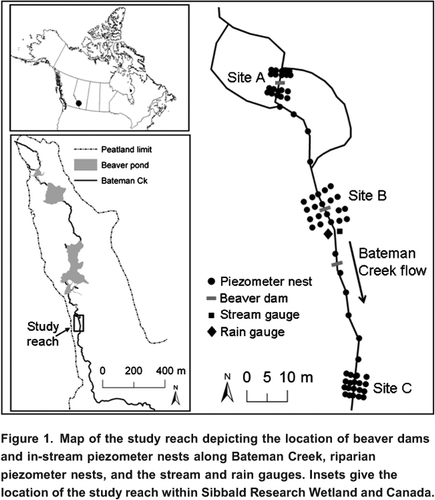
The instrumentation at each of the three sites consisted of four closely spaced transects installed perpendicular to the stream channel to provide high spatial resolution of subsurface flows (). Two transects, spaced 2 m apart were installed upstream of dams 1 and 2, and two similarly spaced transects were installed downstream of each dam. Transects at site C were spaced 5 m apart. Transects consisted of five piezometer nests, each of which was comprised of three piezometers and one water table well. One nest was installed as close to the stream edge as feasible and a second was placed 12 m into the riparian area on both sides of the stream. The fifth nest was placed in the thalweg of the stream. An additional ten piezometer nests were installed in the stream in May 2007 to increase spatial coverage along the 90-m study reach ().
Water table wells were made of 2.54 cm (inner diameter) PVC pipe that was 1.5 m long, slotted every 5 cm, and capped at the end so that sediment did not enter during installation. Wells were installed by hand in the riparian area to the top of the mineral lens. Piezometers installed in the riparian area were made of 1.27 cm (inner diameter) PVC pipe, capped at the bottom, and individually installed with a hand auger in one nest consisting of three pipes 12 cm apart. Each piezometer was installed at a different depth: one at 50 or 75 cm (A), a second at 75 or 100 cm (B), and a third at 140 cm (C) below the ground surface, depending on the depth of the water table. Piezometers installed in the stream were made of the same material and driven into the bed to depths of 60 cm (A) and 85 cm (B) by hand. These piezometers were capped at the bottom and slotted over the last 10 cm, and thus were installed in the mineral lens. Slots were screened with mesh drywall tape to avoid clogging during installation. All wells and piezometers were developed by removing at least three well volumes with a foot valve connected to a length of polypropylene tubing prior to use. Estimates of hydraulic conductivity (K) were made for all piezometers and wells using the Hvorslev method as outlined in Freeze and Cherry (Citation1979). Changes in head were monitored using either an automated pressure transducer (PT2X, Instrumentation Northwest Inc.) put in place before the head was raised, or by manually measuring water level recoveries in piezometers completed in low hydraulic conductivity material.
Depth to water in wells and piezometers was measured as per Westbrook et al. (Citation2006). Stream stage was measured along the outside casing of the A-series piezometers. Water levels in all piezometer nests were measured eight times (at weekly intervals) between June and August in both 2006 and 2007. Continuous stream stage was measured at 0.25 h intervals in the middle of the reach using a float-operated OTT Thalimedes shaft encoder. Stream stage was converted to discharge using a rating curve developed for the site. Rainfall was monitored using a HOBO tipping bucket rain gauge. The locations and elevation of all instruments and beaver dams were surveyed using a total station. Stream bed and bank elevations were also surveyed at 5 m intervals along the study reach.
Data Analysis
Fifteen minute stream stage data from the gauging station were averaged to hourly values. Stream heads taken from the outside of the A-series piezometers were reported as averages separately for 2006 and the periods before and after dam 3 was constructed in 2007.
Significant differences in K among sites were assessed using analysis of variance (ANOVA) with Tukey's post-hoc comparisons. The difference in K between riparian and stream bed piezometers was assessed using a t-test at the 5% significance interval. All statistical tests were conducted using SYSTAT ver. 12.
Vertical hydraulic gradients (VHGs) were estimated by dividing the head difference between the stream and subsurface by the distance between the bed interface and uppermost slot of the screen. Lateral hydraulic gradients (LHGs) were calculated by dividing the head difference between the stream and the riparian piezometer nearest the stream by the horizontal distance between them. Positive hydraulic gradients indicate water movement from the stream bed or riparian area to the stream; negative gradients indicate water flow in the opposite direction. VHGs and LHGs are shown for each sampling day in .
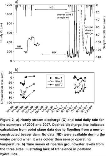
Figure 2. a) Hourly stream discharge (Q) and total daily rain for the summers of 2006 and 2007. Dashed discharge line indicates calculation from point stage data due to flooding from a newly-constructed beaver dam. No data (ND) were available during the winter period when it was colder than sensor operating temperature. b) Time series of riparian groundwater levels from the three sites illustrating lack of transience in peatland hydraulics.
Water table maps for each site were created by hand-contouring mean water table elevation separately in 2006 and 2007. To help elucidate whether stream-aquifer exchange is governed at a small spatial scale (i.e. by hyporheic exchange) or at a larger spatial scale, point hydraulic head data from riparian and stream bed piezometers were hand-contoured to create a series of two-dimensional flownets for slices across the stream above and below the dam 1 at Site A, and for one slice across the stream at Sites B and C. Flownets from 26 June 2007 (baseflow conditions) for these four cross-sections are presented.
We then computed fluxes of water across the stream-bed (vertical) and stream-riparian area (lateral) interfaces for each of the three sites based on a simplified Darcy's Law approach. Thus, vertical and lateral discharges were computed as the product of hydraulic gradient, hydraulic conductivity and the unit area of the stream bed or riparian area normal to the direction of flow. Because the temporal variation in LHGs and VHGs is reasonably constant, we report only mean vertical and lateral discharge values one standard error.
Results
Rainfall, Stream Discharge and Riparian Groundwater Levels
Stream stage responded to rain events in 2006 and the first half of 2007 (). For example, all rain storms >20 mm produce sizable increases in streamflow. After 11 July 2007, however, the newly constructed dam 3 raised the upstream stage, which made the rating curve invalid. The continuous stream stage recorder was moved to a new downstream location on 14 August 2007. Stream discharge in fall 2006 was more stable than in fall 2007 and responded less to small (<20 mm) rain events, presumably due to higher soil moisture in 2007 resulting from it being a wetter year. Riparian groundwater levels at the three sites had a more subdued response to rain events than stream stage ().
Riparian and Streambed Hydraulic Conductivity
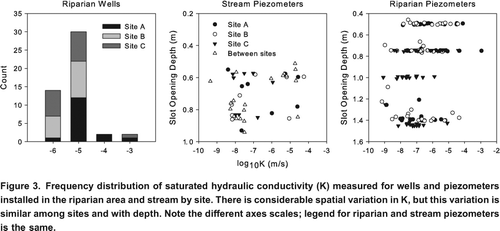
Peat dominates the stratigraphy of the 48 shallow groundwater wells, and is on average 1.3 m thick above the mineral lens. A frequency plot of K shows wells installed in the riparian area have values in the 103 to 106 m/s range, with the greatest proportion of wells having values of 105 m/s (). ANOVA indicates a significant site effect (p=0.016) where wells at Site A have higher K than those at Site C (p=0.014). K values are consistent among wells at Sites A and B (p=0.115) and B and C (p=0.610). Greater variability in hydraulic conductivity is found for the piezometers installed in the riparian area and streambed (). Most riparian piezometers have a K of 105 to 108 m/s whereas most streambed piezometers have a K of 107 to 108 m/s. A t-test indicated this difference is not significant (p=0.260). ANOVA indicates no difference in piezometer K among sites (p=0.099). The range of variation in piezometer K is consistent with depth.
Figure 3. Frequency distribution of saturated hydraulic conductivity (K) measured for wells and piezometers installed in the riparian area and stream by site. There is considerable spatial variation in K, but this variation is similar among sites and with depth. Note the different axes scales; legend for riparian and stream piezometers is the same.
Stream Heads
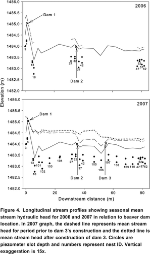
The longitudinal stream profile for 2006 () shows the seasonal average stream stage at each stream piezometer nest for the three study areas. Stream head at piezometer nest 3 is 1.1 m higher than downstream of dam 1 at piezometer nest 13. A large scour hole in the bed is present downstream of dam 1 at nest 18 due to the erosive action of the water flowing over the dam. There is considerable sediment build-up immediately upstream of the dam and thus stream depth is less at nest 8 than nest 3. Stream head is 0.34 m higher upstream of dam 2 than downstream of it. Stream heads along the un-dammed portion of the reach (site C) are similar to those immediately downstream of dam 2. Stream heads in 2007 () are generally higher than in 2006, except upstream of dam 1. The biggest difference occurs between piezometer nest 32 and dam 3. The increased stream head along this 23-m section of the reach following completion of dam 3 caused dam 2 to become submerged.
Figure 4. Longitudinal stream profiles showing seasonal mean stream hydraulic head for 2006 and 2007 in relation to beaver dam location. In 2007 graph, the dashed line represents mean stream head for period prior to dam 3's construction and the dotted line is mean stream head after construction of dam 3. Circles are piezometer slot depth and numbers represent nest ID. Vertical exaggeration is 15x.
Vertical and Lateral Flow Patterns
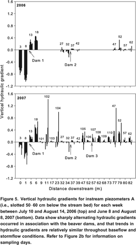
VHGs show that the stream is generally gaining water from the streambed along the reach (). However, sharply alternating VHGs occurred in association with the beaver dams. The stream loses water to the bed above and gains water immediately below beaver dam 1. This pattern is consistent for all sampling dates. A similar pattern at dam 2 is observed in 2006, but the VHGs are considerably less steep than at dam 1. This pattern is not observed near dam 3 after its construction on 11 July 2007, but some individual sample dates do show that the stream loses water above the dam (piezometer 106) and gains water below it (piezometer 107).
Figure 5. Vertical hydraulic gradients for instream piezometers A (i.e., slotted 5060 cm below the stream bed) for each week between July 10 and August 14, 2006 (top) and June 8 and August 8, 2007 (bottom). Data show sharply alternating hydraulic gradients occurred in association with the beaver dams, and that trends in hydraulic gradients are relatively similar throughout baseflow and stormflow conditions. Refer to Figure 2b for information on sampling days.
LHGs () and water table maps () show that patterns of flow differ at the three sites studied. At site A, a lateral looping pattern of water exists around dam 1. Surface water recharges the riparian area above the dam and groundwater discharges back to the stream below the dam. This pattern persists throughout both study years and LHGs are static over time. A similar flow pattern exists in the western riparian area near dam 2, but only in 2006 when the dam is in good repair, i.e., closed and retaining water. East of the stream, groundwater flow is directed toward the stream in both 2006 and 2007. LHGs and water table maps for the un-dammed reach (site C) show that the stream gains water from the adjacent riparian area throughout both 2006 and 2007. The magnitude of the LHG varies, depending on stream discharge. There is no indication of lateral hyporheic flux.
Figure 6. Lateral hydraulic gradients between the stream and riparian area for each week between July 10 and August 14, 2006 (top) and June 8 and August 8, 2007 (bottom). Negative values indicate stream water recharging the riparian aquifer. Data show surface water recharging the riparian area above the dam and groundwater discharging back to the stream below the dam. Directions of hydraulic gradients were maintained throughout baseflow and stormflow conditions.
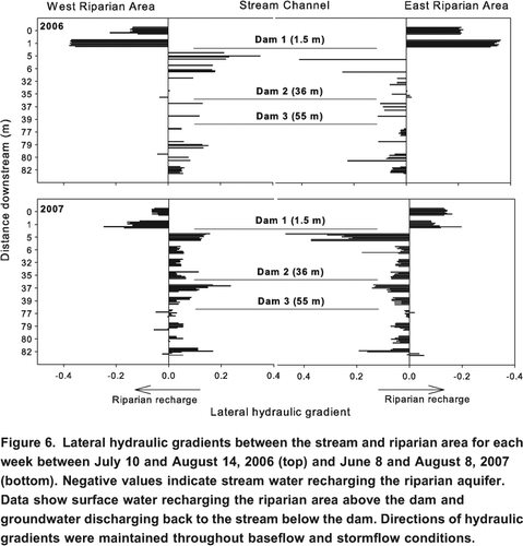
Figure 7. Water table contours derived from mean well hydraulic head observations from 2006 and 2007 at sites A, B, and C. Hatching depicts beaver dam location, circles represent well locations, dotted lines represent stream banks and arrows illustrate direction of main flow vectors. Axis ticks are 1 m. Water table values displayed are elevations (m) above an arbitrary datum of 1483 m.a.s.l. Note differences in water table contour intervals among plots.
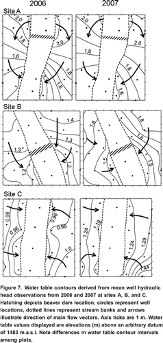
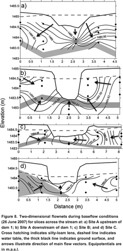
Flownets for slices across the stream suggests that the beaver dam-driven increase in water table elevation is sufficiently high to drive recharge toward the underlying silty-loam lens and hillslopes above dam 1 and back to the stream below it (). At Site B, the main groundwater flow vector is horizontal and toward the stream. Flow is also toward the stream at Site C, but has a greater vertical component than Site B. Hydraulic gradients along the main flow vectors were at least twice as great at Site A than Sites B and C during baseflow conditions.
Figure 8. Two-dimensional flownets during baseflow conditions (26 June 2007) for slices across the stream at: a) Site A upstream of dam 1; b) Site A downstream of dam 1; c) Site B; and d) Site C. Cross hatching indicates silty-loam lens, dashed line indicates water table, the thick black line indicates ground surface, and arrows illustrate direction of main flow vectors. Equipotentials are in m.a.s.l.
Hyporheic Fluxes
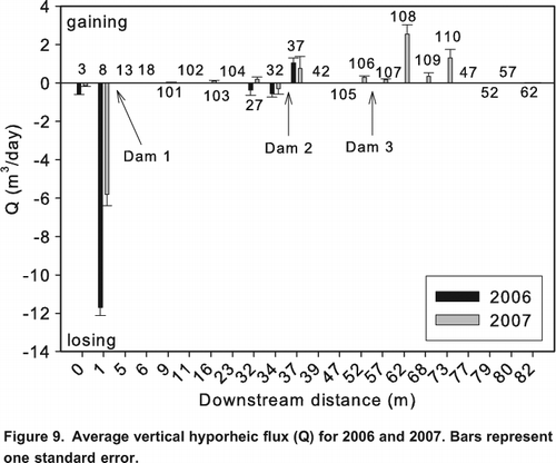
Despite fairly large VHGs near dam 1, only a moderate volume of water recharged the streambed (<12 m3/day per m of stream bed, where baseflow is 430 m3/day) upstream of it in both study years (). Most of this water does not return to the stream immediately downstream of the dam as vertical fluxes there were near zero. Some shallow vertical hyporheic exchange, based on the recharge-discharge pattern of flow beneath the dam as inferred from the VHG's, does occur upstream and downstream of dam 2 in 2006, but values are <1 m3/day per m of stream bed. The stream gains water from the groundwater system between dam 2 and the undammed site (i.e., piezometer nests 106 through 110). The largest gain (2.5 m3/day per m of stream bed) is observed 9 m downstream of dam 3. Negligible exchange of water between the stream and groundwater system was measured along the un-dammed reach. Overall, vertical fluxes do not balance along the reach; the 90-m long reach of stream has an average net loss of 0.53 m3/day to its bed in 2007 due to the high loss of water upstream of dam 1 relative to fluxes measured along the rest of the stream reach.
Figure 9. Average vertical hyporheic flux (Q) for 2006 and 2007. Bars represent one standard error.
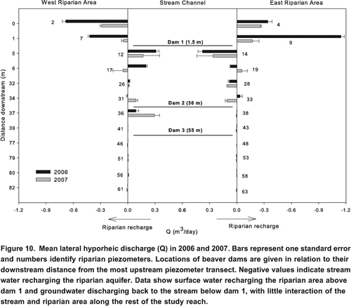
Lateral water fluxes along the reach varied considerably; from near zero to 1.14 m3/day per m of stream bank (). Water fluxes around dam 1 are largest, ranging from 1.14 to 0.38 m3/day per m of stream bank in 2006 and from 0.29 to 0.26 m3/day per m of stream bank in 2007. The stream loses more water to the riparian area upstream of dam 1 than it gains below it only 37% and 49% of the water lost above dam 1 returns to the stream below it in 2006 and 2007, respectively. A relatively large influx of water (>0.09 m3/day per m of stream bank) to the stream was measured on the west bank immediately below dam 2 in both 2006 and 2007. However, outflux of stream water above dam 2 is negligible in 2006 and nonexistent in 2007. Lateral fluxes are not greater than 0.009 m3/day per m of stream bank along the un-dammed reach in either study year.
Figure 10. Mean lateral hyporheic discharge (Q) in 2006 and 2007. Bars represent one standard error and numbers identify riparian piezometers. Locations of beaver dams are given in relation to their downstream distance from the most upstream piezometer transect. Negative values indicate stream water recharging the riparian aquifer. Data show surface water recharging the riparian area above dam 1 and groundwater discharging back to the stream below dam 1, with little interaction of the stream and riparian area along the rest of the study reach.
Discussion
It was expected that lateral hyporheic fluxes would be greater than vertical ones as many researchers (e.g. Quinton et al. Citation2008) have shown that peat hydraulic conductivity declines with depth, similar to the pattern found for mineral substrates. The control of hyporheic exchange by the hydraulic conductivities of the bed and bank material has been demonstrated in several studies (Triska et al., Citation1993; Butturini et al., Citation2002; Wright et al., Citation2005). For example, Triska et al. (Citation1993) found that the permeability of the bank side sediments regulated the proportion of stream water and groundwater that was in the hyporheic zone in a small gravel-cobble stream in California. Further, Greenwald et al. (Citation2008) found that the vertical development of hyporheic flow in an arctic cobble stream with high hydraulic conductivity was greater than the vertical development in a nearby peat dominated stream where sediments had lower hydraulic conductivity but the streams otherwise were of similar size and geometry.
Contrary to our expectation, however, results showed that vertical fluxes were often comparable to or exceeded lateral fluxes despite statistically similar stream bed and riparian substrate hydraulic conductivity. However, riparian substrate tended to have a higher hydraulic conductivity (mean=1.5 105 m/s) than the stream bed (mean=5.3 106 m/s). Modeling exercises have demonstrated the high sensitivity of hyporheic exchange to streambed and bank hydraulic conductivity (Wondzell and Swanson, Citation1996; Lautz and Siegel, Citation2006).
Although hydraulic properties of bed and bank substrate are key in influencing hyporheic exchange, physical features of channels can also regulate hyporheic exchange. The largest difference in vertical and lateral flows was observed at site A. Beaver create step-pool stream profiles through building dams (Naiman et al., Citation1986), such as was the case at site A. Gooseff et al. (Citation2006) showed how high head gradients attributed to step-pool stream profiles have been shown to promote deeper hyporheic exchange. Lautz and Seigel (2006) demonstrated that vertical flow dominated over lateral flow in an arid mountain stream due to large difference in stream stage above and below debris dams. Throughout the rest of the study reach, the main channel flow gradient could have limited hyporheic fluxes in both directions. This has been shown to be the case in river systems where bed and bank hydraulic conductivities are relatively homogeneous (Wondzell and Swanson, Citation1996). Also, riparian water table in relation to stream stage can limit lateral hyporheic exchange (Lautz et al., Citation2006).
We also expected that hyporheic fluxes would be enhanced near beaver dams due to them increasing hydraulic gradients inland and from below the stream. Our data partially support this hypothesis, as they show that there is little hyporheic exchange (vertical or lateral) along the studied stream reach in the absence of beaver dams. Around dams 1 and 2, vertical hydraulic gradients show a distinct pattern wherein flow loops underneath the dams. This pattern of stream water movement into the bed upstream of the dams and out of the bed downstream of the dams persisted during both low or high flows. Strong vertical gradients were created by the impoundment of water upstream of the dams, which increased stream hydraulic head, showing a gradient exists for stream water to flow down into the bed and out into the banks. Downstream of a dam, the lower stream stage created an area of low hydraulic head and a pathway for water to come back into the stream. Other researchers have also shown VHG's indicating a downwelling-upwelling flow pathway underneath beaver and debris dams (White, Citation1990; Stofleth et al., Citation2008). Such a flow pattern was not observed at the undammed site C.
Despite strong hydraulic gradients for flow, it seems that flow is not actually looping underneath the dams as very little water actually moved along these flowpaths. Much of the stream water that recharged the aquifer above dams 1 and 2 did not return to the stream downstream of the dams. Therefore, we caution other researchers who tend to report only hydraulic gradients rather than fluxes. For example, the water table maps () indicate that the stream is generally gaining, at least on the studied reach. Flux data, however, show that the presence of beaver dams causes it to be a losing stream. Gaining and losing are stream descriptors that are typically based on gradients for flows rather than flux measurements. Our estimates of flux are comparable to those Hester and Doyle (Citation2008) achieved through modelling using a bed sediment hydraulic conductivity of 105 m/s, assuming their fluxes are per metre of stream bed.
Our results suggest that: i) the stream may vertically recharge the underlying aquifer upstream of the dams, ii) downwelling water above the dam is flowing below the dam and then upwards at shallow depths of <50 cm in the bed downstream of the dam, or iii) the hyporheic flow path created by the dams is considerably longer than has been shown in other studies and thus our instrumentation was not sufficiently spatially expansive. Explanations i) and ii) are the most likely. The effect of a water table rise behind a dam may be amplified in settings where the lateral bedrock valley sides are in close proximity. At the Sibbald wetland, it is possible that a broad increase in water table elevation is sufficiently high to drive recharge through the silty-loam lens. Alternatively, one might expect the low conductivity lens to act as an aquitard, which would distort hyporheic flow pathways such that flow paths become concentrated through the upper peat. Much of the stream water recharging the peat aquifer upstream of dam 1 could thus have potentially returned back to the stream somewhere downstream. For example, site C gained water from the peat aquifer throughout the study, but it is unclear from our hydrometric data whether this is hyporheic water or groundwater. Tracer studies or hydrologic modeling would be useful in evaluating if stream water flowing into the bed above dam 1 returns to the stream somewhere downstream or instead becomes lost to the groundwater flow system.
Water table maps and discharge data show the existence of a lateral looping pattern of hyporheic exchange around dam 1. Subsurface flow laterally looping around a beaver dam has also been demonstrated by Hill and Duval (Citation2009). A similar looping flow pattern was not observed near dam 2 however. This suggests two possibilities. One, that dam persistence is important in creating conditions conducive to enhanced hyporheic flux. Perhaps dams (2 and 3) may have been too short lived for hyporheic flow paths to establish. Two, that there exists a threshold dam size in order to generate three dimensional looping hyporheic flow paths around dams. For our study, the dam height threshold was between 0.67 m (height of dam 2) and 1.05 m (height of dam 1). Other studies have demonstrated how beaver, debris or other small dams 0.5 m were sufficient to generate vertical hyporheic exchange (Kasahara and Wondzell, Citation2003; Lautz and Siegel, Citation2006; Hester and Doyle, Citation2008), which is consistent with our findings. Further, Hester and Doyle (Citation2008) used a modeling exercise to demonstrate that enhanced hyporheic flow gradients translated into increased downwelling flux rates with larger dams. Hill et al. (Citation1998) researched lateral hyporheic exchanges between pool riffle sequences in a third order stream in southern Ontario and found very low slope thresholds of 23% for riffles and surface water slopes as low as <1% for pools were needed to generate hyporheic flows.
For lateral hyporheic flows to develop in response to in-channel structures such as beaver dams, elevation of the adjacent riparian water table also needs to be considered. It is likely that the increased stream head above dam 2 was insufficient to generate lateral hyporheic exchange given the small hydraulic gradient between the stream and riparian aquifer. Lautz et al. (Citation2006) previously demonstrated how high riparian water tables in relation to stream stage can limit lateral hyporheic exchange. Future studies should further explore the idea that threshold beaver dam heights that generate enhanced hyporheic exchange may exist for specific substrate types, and evaluate how riparian water table position affects them. Flume experiments would be useful in elucidating the influence of obstructions of differing heights on the length of time required to generate looping hyporheic flow patterns. As well, exploration into whether threshold dam heights translate into water table mounds that can become large enough that they influence the regional groundwater flow system would be useful. For example, does elevation of the stream head and riparian water table by a beaver dam facilitate the driving of flows through underlying silty lenses thereby recharging the deeper valley aquifer?
Conclusion
This study shows how beaver dams restructure subsurface flow directions by increasing hydraulic gradients inland from and beneath the stream, which enhanced water fluxes between the riparian area and stream compared to a reach without dams. Not as much water looped around the dam and returned to the stream as would be expected given the strong gradients for flow, mostly due to low substrate hydraulic conductivity. Instead, it appeared that the beaver dams effectively changed the stream from a gaining to a losing system through enhancing vertical recharge, and/or creating long hyporheic flowpaths. This result contrasts with previous findings in that beaver dams have only been shown to cause water loss to the groundwater system along static to losing stream reaches (Lautz and Siegel, Citation2006; Hill and Duval, Citation2009). As longer hyporheic flowpaths extend the length of temporary storage of water in stream bed and bank sediments, results presented herein may have implications for nutrient retention and export from peatlands (Hill and Duval, Citation2009), which can influence downstream water quality. Within the study site (Sibbald Research Wetland) there are numerous large dams (20100 m or longer and 0.5 to 2.5 m high; ) that have very large ponds associated with them. If our results are up-scaled to these larger dams, we expect they have the potential to hydrologically connect much of the peatland body to the stream through longer hyporheic flow paths. Beaver dams are prevalent throughout valley bottom wetlands in the Rocky Mountains. Many of these valley bottoms may be wetlands simply because beaver may be maintaining riparian water tables near or at the ground surface by creating larger-scale (valley sized) hyporheic flow paths. Such hydrological connectivity may persist throughout wet and dry periods as this study and others (e.g., Westbrook et al., Citation2006) have shown that beaver keep hydrological conditions relatively static.
Acknowledgements
Funding for this work came from a NSERC Discovery Grant, a University of Saskatchewan New Faculty Award, and a Dean's Scholarship. Thank you to Daryl Janzen, Erin Shaw, Gro Lilbaek, Warren Helgason, Michael Solohub, Adam Minke, and May Guan for field assistance, and all the staff at the University of Calgary Biogeosciences Institute for logistical support. Insightful comments from two anonymous reviewers helped improved the quality of this manuscript.
References
- Baker, B.W. and E.P. Hill. 2003. Beaver (Castor canadensis). In Wild mammals of North America: biology, management, and conservation, ed. G.A. Feldhamer, B.C. Thompson and J.A. Chapman. Johns Hopkins University Press, 288310.
- Boulton , A.J. and Stanley , E.H. 1995 . Hyporheic processes during flooding and drying of a Sonoran Desert stream. II. Faunal dynamics . Archiv fr Hydrobiologie , 134 : 27 – 52 .
- Butturini , A. , Bernal , S. , Sabater , S. and Sabater , F. 2002 . The influence of riparian-hyporheic zone on the hydrological responses in an intermittent stream . Hydrology and Earth System Sciences , 6 ( 3 ) : 515 – 525 .
- Calles , O. , Nyberg , L. and Greenberg , L. 2007 . Temporal and spatial variation in quality of hyporheic water in one unregulated and two regulated boreal rivers . River Research and Applications , 23 : 829 – 842 .
- Findlay , S. 1995 . Importance of surface-subsurface exchange in stream ecosystems: the hyporheic zone . Limnology and Oceanography , 40 : 159 – 164 .
- Freeze, R.A. and J.A. Cherry. 1979. Groundwater. Prentice Hall, 604 pp.
- Gooseff , M.N. , Anderson , J.K. , Wondzell , S.M. , LaNier , J. and Haggerty , R. 2006 . A modelling study of hyporheic exchange pattern and the sequence, size, and spacing of stream bedforms in mountain stream networks, Oregon, USA . Hydrological Processes , 20 : 2443 – 2457 .
- Greenwald , M.J. , Bowden , W.B. , Gooseff , M.N. , Zarnetske , J.P. , McNamara , J.P. , Bradford , J.H. and Brosten , T.R. 2008 . Hyporheic exchange and water chemistry of two arctic tundra streams of contrasting geomorphology . Journal of Geophysical Research , 113 G02029
- Harvey, J.W. and B.J. Wagner. 2000. Quantifying hydrologic interactions between streams and their subsurface hyporheic zones. In Streams and ground waters, ed. J.B. Jones and P.J. Mulholland. Academic Press, 344.
- Hester, E.T. and M.W. Doyle. 2008. In-stream geomorphic structures as drivers of hyporheic exchange. Water Resources Research 44: doi:10.1029/2006WR005810.
- Hill , A.R. and Duval , T.P. 2009 . Beaver dams along an agricultural stream in southern Ontario, Canada: their impact on riparian zone hydrology and nitrogen chemistry . Hydrological Processes , 23 : 1324 – 1336 .
- Hill , A.R. and Lymburner , D.J. 1998 . Hyporheic zone chemistry and stream-subsurface exchange in two groundwater-fed streams . Canadian Journal of Fisheries and Aquatic Sciences , 55 : 495 – 506 .
- Hill , A.R. , Labadia , C.F. and Sanmugadas , K. 1998 . Hyporheic zone hydrology and nitrogen dynamics in relation to the streambed topography of a N-rich stream . Biogeochemistry , 42 : 285 – 310 .
- Holden , J. and Burt , T.P. 2003 . Hydraulic conductivity in upland blanket peat: measurement and variability . Hydrological Processes , 17 : 1227 – 1237 .
- Jones , J.B. and Holmes , R.M. 1996 . Surface-subsurface interactions in stream ecosystems . Trends in Ecology and Evolution , 11 : 239 – 242 .
- Jones , K.L. , Poole , G.C. , Woessner , W.W. , Vitale , M.V. , Boer , B.R. , O'Daniel , S.J. , Thomas , S.A. and Geffen , B.A. 2008 . Geomorphology, hydrology, and aquatic vegetation drive seasonal hyporheic flow patterns across a gravel-dominated floodplain . Hydrological Processes , 22 : 2105 – 2113 .
- Kasahara , T. and Hill , A.R. 2006 . Hyporheic exchange flows induced by constructed riffles and steps in lowland streams in southern Ontario, Canada . Hydrological Processes , 20 ( 20 ) : 4287 – 4305 .
- Kasahara , T. and Wondzell , S.M. 2003 . Geomorphic controls on hyporheic exchange flow in mountain streams . Water Resources Research , 39 ( 1 ) : 1005
- Lautz , L.K. , Siegel , D.I. and Bauer , R.L. 2006 . Impact of debris dams on hyporheic interaction along a semi-arid stream . Hydrological Processes , 20 : 183 – 196 .
- Lautz , L.K. and Siegel , D.I. 2006 . Modeling surface and ground water mixing in the hyporheic zone using MODFLOW and MT3D . Advances in Water Resources , 29 : 1618 – 1633 .
- Naiman , R.J. , Johnston , C.A. and Kelley , J.C. 1988 . Alteration of North American streams by beaver . BioScience , 38 ( 11 ) : 753 – 762 .
- Naiman , R.J. , Melillo , J.M. and Hobbie , J.E. 1986 . Ecosystem alteration of boreal forest streams by beaver (Castor canadensis) . Ecology , 67 ( 5 ) : 1254 – 1269 .
- Packman , A.I. and Salehin , M. 2003 . Relative roles of streamflow and sedimentary conditions in controlling hyporheic exchange . Hydrobiologia , 494 : 291 – 297 .
- Poole, G.C., S.J. ODaniel, K.L. Jones, W.W. Woessner, E.S. Bernhardt, A.M. Helton, J.A. Stanford, B.R. Boer, and T.J. Beechie. 2008. Hydrologic spiralling: the role of multiple interactive flow paths in stream ecosystems. River Research and Applications 24: 10181031. doi:10.1002/rra.1099.
- Quinton, W.L., M. Hayashi, and S.K. Carey. 2008. Peat hydraulic conductivity in cold regions and its relation to pore size and geometry. Hydrological Processes 22: 28292837. doi:10.1002/hyp.7027.
- Rosell , F. , Bozsr , O. , Collen , P. and Parker , H. 2005 . Ecological impact of beavers Castor fiber and Castor canadensis and their ability to modify ecosystems . Mammal Review , 35 ( 3&4 ) : 248 – 276 .
- Stofleth , J.M. , Shield , F.J. and Fox , G.A. 2008 . Hyporheic and total transient storage in small, sand-bed streams . Hydrological Processes , 22 : 1885 – 1894 .
- Triska , F.J. , Duff , J.H. and Avanzino , R.J. 1993 . The role of water exchange between a stream channel and its hyporheic zone in nitrogen cycling at the terrestrial-aquatic interface . Hydrobiologia , 251 : 167 – 184 .
- Triska , F.J. , Kennedy , V.C. , Avanzino , R.J. , Zellweger , G.W. and Bencala , K.E. 1989 . Retention and transport of nutrients in a third-order stream in northwestern California: hyporheic processes . Ecology , 70 : 1893 – 1905 .
- Westbrook, C.J., D.J. Cooper, and B.W. Baker. 2006. Beaver dams and overbank floods influence groundwater surface water interactions of a Rocky Mountain riparian area. Water Resources Research 42: doi:10.1029/2005WR004560.
- White , D.S. 1990 . Biological relationships to convective flow patterns within streambeds . Hydrobiologia , 196 : 149 – 158 .
- Whiting , P.J. and Pomeranets , M. 1997 . A numerical study of bank storage and its contribution to streamflow . Journal of Hydrology , 202 : 121 – 136 .
- Wondzell , S.M. and Swanson , F.J. 1996 . Seasonal and storm dynamics of the hyporheic zone of a 4th-order mountain stream. I: Hydrologic processes . Journal of the North American Benthological Society , 15 : 3 – 19 .
- Wondzell , S.M. and Swanson , F.J. 1999 . Floods, channel change, and the hyporheic zone . Water Resources Research , 35 : 555 – 567 .
- Wright , K.K. , Baxter , C.V. and Li , J.L. 2005 . Restricted hyporheic exchange in an alluvial river system: implications for theory and management . Journal of the North American Benthological Society , 24 ( 3 ) : 447 – 460 .
- Zarnetske, J.P., M.N. Gooseff, W.B. Bowden, M.J. Greenwald, T.R. Brosten, J.H. Bradford, and J.P. McNamara. 2008. Influence of morphology and permafrost dynamics on hyporheic exchange in arctic headwater streams under warming climate conditions. Geophysical Research Letters 35: L02501, doi:10.1029/2007GL032049.