Figures & data
Figure 1. Musculoskeletal-inspired robot arm driven by three pairs of antagonistic actuators. and
move the first joint,
and
move the second joint, and
and
move both joints.
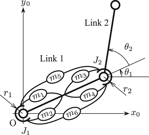
Figure 2. Force generation model of the actuator. It consists of an elastic element, a viscous element, and a force generator that generates active forces.
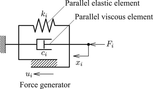
Figure 3. Coactivation pattern of actuators represented by the new bases . The black actuators output a unit active force in the positive direction, the white actuators in the negative direction, and the gray actuators do not output any actives. (a)
, (b)
, (c)
, (d)
, (e)
, (f)
.
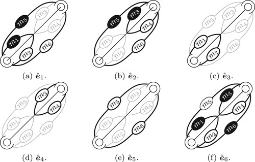
Table 1. Physical parameters of the musculoskeletal-inspired robot arm.
Figure 4. Stiffness ellipsoid representing the tip stiffness properties.
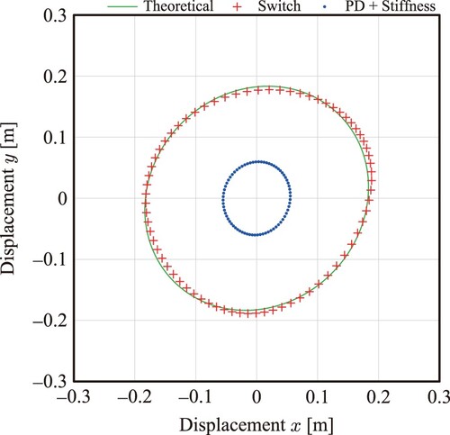
Figure 5. Response of the tip position and velocity. We performed position control in the first five seconds, switched from position control to stiffness control at seconds, and applied an external force to the hand at
seconds. (a) Tip position (x-direction), (b) Tip position (y-direction), (c) Tip velocity (x-direction), (d) Tip velocity (y-direction).
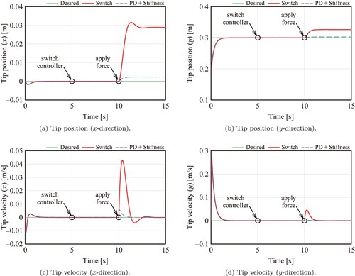
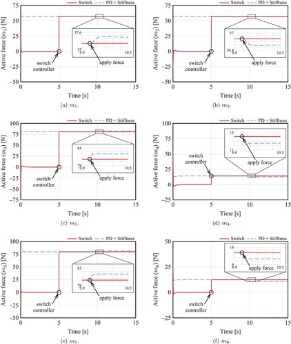
Figure 6. Active forces. We performed position control in the first five seconds, switched from position control to stiffness control at t = 5 seconds, and applied an external force to the hand at t = 10 seconds. (a) , (b)
, (c)
, (d)
, (e)
, (f)
.