
Figures & data
Table 1 Summary of Data Extracted from Some Articles
Figure 1 A 32-year-old male with several cavernous malformations who was being evaluated for intraparenchymal hemorrhage. (A) A left frontal cavernous malformation is visible on a T2-weighted image, and it is encircled by a significant haemosiderin ring. (B) Multiple punctate hypointense foci can be seen on the GE T2*-weighted image, which are representative of tiny cavernous malformations in both hemispheres (arrows).Citation18
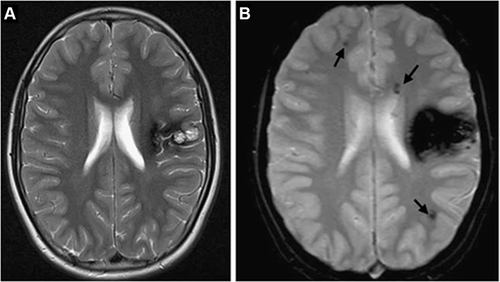
Figure 2 With increasing TE, T2* weighting rises. This is so that more dephasing can occur prior to the development of an echo when the TE is longer. (A) TE = 10ms, (B) TE = 30ms, (C) TE = 50ms [Courtesy Allen D Elster, MRIQuestions.com].Citation19
![Figure 2 With increasing TE, T2* weighting rises. This is so that more dephasing can occur prior to the development of an echo when the TE is longer. (A) TE = 10ms, (B) TE = 30ms, (C) TE = 50ms [Courtesy Allen D Elster, MRIQuestions.com].Citation19](/cms/asset/f6ceffe9-fd4e-403d-b607-dc6325ae4551/drmi_a_12152315_f0002_c.jpg)
Figure 3 Iron-particle-related susceptibility artifact in mascara indicated by yellow solid arrow [Courtesy Allen D Elster, MRIQuestions.com].Citation21
![Figure 3 Iron-particle-related susceptibility artifact in mascara indicated by yellow solid arrow [Courtesy Allen D Elster, MRIQuestions.com].Citation21](/cms/asset/24fafa53-6f54-4708-b434-9fce97631d62/drmi_a_12152315_f0003_c.jpg)
Figure 4 Chemical Shift artifact in the spine. At the junction between the vertebrae and the disk, there are a series of light and dark bands (indicated by solid red arrows) [Courtesy Allen D Elster, MRIQuestions.com].Citation22
![Figure 4 Chemical Shift artifact in the spine. At the junction between the vertebrae and the disk, there are a series of light and dark bands (indicated by solid red arrows) [Courtesy Allen D Elster, MRIQuestions.com].Citation22](/cms/asset/6aeb7842-80c5-4c67-8a7d-013d3c0c5c19/drmi_a_12152315_f0004_c.jpg)
Figure 5 At the water-fat interface, there is a chemical shift artifact. The axial T1-weighted GRE MR image shows a dark rim on one border of the kidney and a bright rim on the opposite edge (indicated by white solid arrows), an artifact caused by the difference in fat and water precessional frequencies [Courtesy Allen D Elster, MRIQuestions.com].Citation22
![Figure 5 At the water-fat interface, there is a chemical shift artifact. The axial T1-weighted GRE MR image shows a dark rim on one border of the kidney and a bright rim on the opposite edge (indicated by white solid arrows), an artifact caused by the difference in fat and water precessional frequencies [Courtesy Allen D Elster, MRIQuestions.com].Citation22](/cms/asset/2d5569fe-99a9-4289-a899-325cfbef5ce7/drmi_a_12152315_f0005_c.jpg)
Figure 6 Chemical Shift Artifact: The bandwidth per pixel in the phase-encode direction of EPI is very tiny (i.e., on the order of 1kHz). This narrow bandwidth in the phase-encode direction translates into a significant artifact (indicated by the solid yellow arrows) that can be up to 1 cm wide at 1.5 T, where the fat/water chemical shift is around 220 Hz [Courtesy Allen D Elster, MRIQuestions.com].Citation26
![Figure 6 Chemical Shift Artifact: The bandwidth per pixel in the phase-encode direction of EPI is very tiny (i.e., on the order of 1kHz). This narrow bandwidth in the phase-encode direction translates into a significant artifact (indicated by the solid yellow arrows) that can be up to 1 cm wide at 1.5 T, where the fat/water chemical shift is around 220 Hz [Courtesy Allen D Elster, MRIQuestions.com].Citation26](/cms/asset/fa5a9ba5-1d61-4919-95c2-2dca43b8f5f2/drmi_a_12152315_f0006_c.jpg)
Figure 7 Phase cancellation chemical shift artifact indicated by solid yellow arrows of the abdomen. This form of chemical shift artifact occurs exclusively in gradient echo imaging [Courtesy Allen D Elster, MRIQuestions.com].Citation27
![Figure 7 Phase cancellation chemical shift artifact indicated by solid yellow arrows of the abdomen. This form of chemical shift artifact occurs exclusively in gradient echo imaging [Courtesy Allen D Elster, MRIQuestions.com].Citation27](/cms/asset/71213f26-adcb-4703-83a8-5a1fb2820b99/drmi_a_12152315_f0007_c.jpg)
Figure 8 Effects of dielectric pads on 3T pelvic MRI artifact reduction. The solid red arrow in (A) depicts a signal dropout in the absence of a dielectric pad. (B) Signal is enhanced by the use of a dielectric pad [Courtesy Allen D Elster, MRIQuestions.com].Citation37
![Figure 8 Effects of dielectric pads on 3T pelvic MRI artifact reduction. The solid red arrow in (A) depicts a signal dropout in the absence of a dielectric pad. (B) Signal is enhanced by the use of a dielectric pad [Courtesy Allen D Elster, MRIQuestions.com].Citation37](/cms/asset/93ee5e5a-853a-4890-a24d-5418e56a4632/drmi_a_12152315_f0008_c.jpg)