Figures & data
Figure 1. The tethered crawling robot is introduced into the thoracic cavity through a small port below the sternum (green circle), avoiding the area occupied by the lungs (outlined by the dashed blue line). It attaches to the epicardial surface of the heart and travels to the desired location for therapy under control of the physician. [Color version available online]
![Figure 1. The tethered crawling robot is introduced into the thoracic cavity through a small port below the sternum (green circle), avoiding the area occupied by the lungs (outlined by the dashed blue line). It attaches to the epicardial surface of the heart and travels to the desired location for therapy under control of the physician. [Color version available online]](/cms/asset/b6c9be11-05b9-4dda-b3f7-d273a48f9abd/icsu_a_123002_f0001_b.jpg)
Figure 2. The first crawling robot prototype (upper: 18 mm tall, 14 mm wide) and second prototype (lower: 11 mm tall, 10 mm wide). The second prototype features a needle for myocardial injection, which is retracted during locomotion. The lines mark a 25.4-mm grid, and a standard pencil is included for scale.
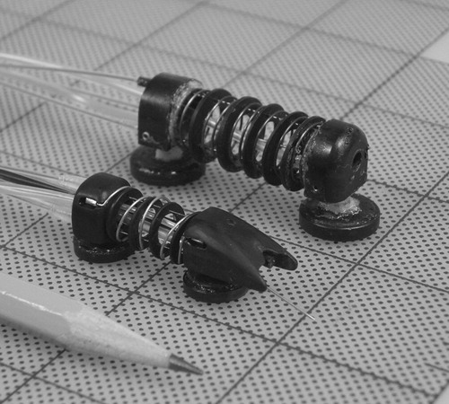
Figure 3. (a) Forward locomotion cycle of the robot (the bold ring indicates the body that is locked to the surface via suction). (b) Steering the robot. (c) The rigid spacer disks allow HeartLander to make sharp turns without the wires bowing. Two rotational degrees of freedom allow it to steer as well as to conform to curved surfaces (a 40-mm diameter table tennis ball shown here).
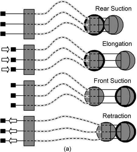
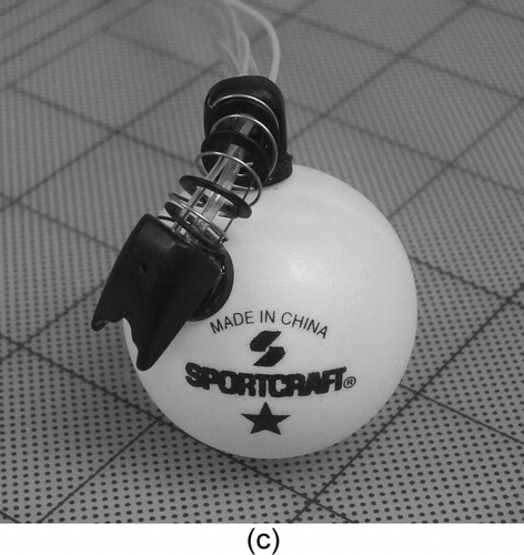
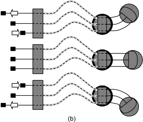
Figure 4. (a) The HeartLander control interface, including the joystick to control locomotion (and eventually therapy), and the monitor to display video from the device camera. (b) View of the left anterior descending artery (LADA) through the device camera. [Color version available online]
![Figure 4. (a) The HeartLander control interface, including the joystick to control locomotion (and eventually therapy), and the monitor to display video from the device camera. (b) View of the left anterior descending artery (LADA) through the device camera. [Color version available online]](/cms/asset/71736021-1f90-46e2-bb6c-f2ffdb1166e3/icsu_a_123002_f0004_b.jpg)
Figure 5. A time sequence of photographs showing the first HeartLander prototype crossing the surface of an exposed beating porcine heart with excised pericardium. [Color version available online]
![Figure 5. A time sequence of photographs showing the first HeartLander prototype crossing the surface of an exposed beating porcine heart with excised pericardium. [Color version available online]](/cms/asset/8e289601-cc60-487e-ae0d-bb1c471d8e30/icsu_a_123002_f0005_b.jpg)
Figure 6. A time sequence showing the second prototype walking on a beating porcine heart with the pericardium intact. The lower arrow indicates the location of the pericardial incision, and the upper arrow indicates the trailing edge of the device. The 15-mm port (green) can be seen in the upper-right corner. [Color version available online]
![Figure 6. A time sequence showing the second prototype walking on a beating porcine heart with the pericardium intact. The lower arrow indicates the location of the pericardial incision, and the upper arrow indicates the trailing edge of the device. The 15-mm port (green) can be seen in the upper-right corner. [Color version available online]](/cms/asset/6b4d05c9-f287-4945-aa17-959920579297/icsu_a_123002_f0006_b.jpg)
Figure 7. The second prototype (viewed beneath the pericardium by the SVP) (a) positioning for myocardial injection (needle highlighted by the arrow) and (b) performing a myocardial injection of tissue dye. (c) The injection sites viewed on the excised porcine heart. [Color version available online]
![Figure 7. The second prototype (viewed beneath the pericardium by the SVP) (a) positioning for myocardial injection (needle highlighted by the arrow) and (b) performing a myocardial injection of tissue dye. (c) The injection sites viewed on the excised porcine heart. [Color version available online]](/cms/asset/a161914a-0991-4a9b-8278-c616e592d11b/icsu_a_123002_f0007_b.jpg)
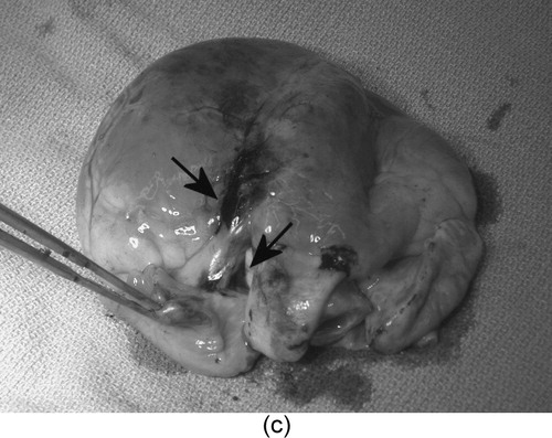
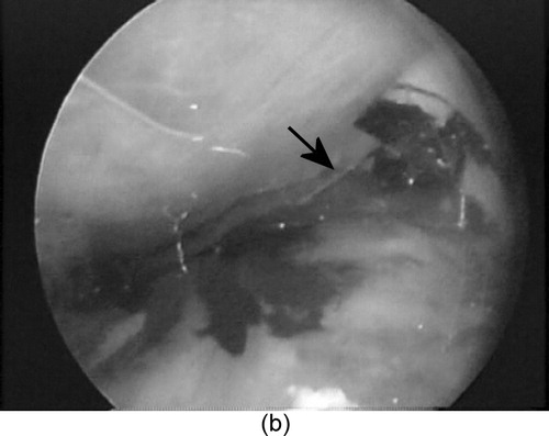
Table I. Force required to dislodge HeartLander from epicardium in porcine model in vivo when pulling on tether.