
Abstract
Microwave ablation (MWA) is becoming an increasingly important minimally invasive treatment option for localized tumors in many organ systems due to recent advancements in microwave technology that have conferred many advantages over other tumor ablation modalities. Despite these improvements in technology and development of applicators for site-specific tumor applications, the vast majority of commercially available MWA applicators are generally designed to create large-volume, symmetric, ellipsoid or spherically-shaped treatment zones and often lack the consistency, predictability, and spatial control needed to treat tumor targets near critical structures that are vulnerable to inadvertent thermal injury. The relatively new development and ongoing translation of directional microwave ablation (DMWA) technology, however, has the potential to confer an added level of control over the treatment zone shape relative to applicator position, and shows great promise to expand MWA’s clinical applicability in treating tumors in challenging locations. This paper presents a review of the industry-standard commercially available MWA technology, its clinical applications, and its limitations when used for minimally-invasive tumor treatment in medical practice followed by discussion of new advancements in experimental directional microwave ablation (DMWA) technology, various techniques and approaches to its use, and examples of how this technology may be used to treat tumors in challenging locations that may otherwise preclude safe treatment by conventional omni-directional MWA devices.
Introduction
Thermal ablation (TA) has become a well-established treatment alternative for localized cancers in patients who are otherwise ineligible for (or refuse) surgery or other physically demanding treatments such as radiation therapy or chemotherapy [Citation1]. TA is also gaining acceptance as a minimally invasive option for palliative care [Citation2,Citation3]. The use of microwave energy for TA is becoming increasingly important for treatment of disease in a diverse range of sites [Citation4,Citation5]. There are several advantages to using microwave energy over other energy modalities (notably radiofrequency ablation (RFA) and cryoablation) that have empowered this trend including the capability of achieving higher peak temperatures throughout the treatment zone, increased ability to penetrate through high-impedance tissues, diminished susceptibility to heat sink effects, ability to rapidly heat larger volumes of tissue via simultaneous emission of microwave energy through multiple applicators positioned in various arrays, and the convenience of energy emission without the need for ancillary circuit components (such as grounding pads) [Citation5,Citation6].
Operators may control microwave ablation zone volume by selecting the number and configuration of the treatment applicator(s) and the applied energy settings (the amount of applied MW power from the generator source, and the overall treatment duration). However, by manipulating these controls for conventional omni-directional MWA technology, operators are only able to generate a proportional spherical or ellipsoidal ablation zone shape; existing technology does not offer selective control of length (height, z), width (diameter, d), or angle (phi) of the treatment zone. Furthermore, modern imaging guidance techniques still have practical limitations in visualizing and monitoring the extent of the treatment zone in real-time during thermal ablation. Although several software platforms exist for planning and modeling of intended treatment zones, these tools are currently unable to account for the effects associated with microwave energy transmission through various tissue types and distortion of the treatment zone that occurs at tissue interfaces, which can result in a discrepancy between the expected (modeled) and observed extent of the treatment zone. As a result, clinical users are largely left with only practical information gained through individual experience with a particular ablation system to balance the risk of incomplete ablation of the target tumor against risk for thermal injury to nearby critical structures.
It is now a well-known principle that the most consistent and predictable dimension of the MWA treatment zone is the extent to which it extends along the longitudinal axis from the tip of the applicator, and many operators deliberately place the applicator such that the tip points toward any tissue structure to which collateral injury intends to be avoided. Based on tumor location, patient positioning, or body habitus, however, percutaneous placement with specific orientation of the MWA applicator in this fashion may not be physically possible. The somewhat limited spatial control and precision of conventional omni-directional MWA devices therefore still falls short of the ideal, and can still restrict the applicability of these devices in certain clinical scenarios based on tumor size or location.
Current clinical MWA applicators
Overview
MWA systems in current clinical use almost exclusively consist of a needlelike applicator which is inserted centrally into a target tumor, either by direct visualization using an open surgical approach or percutaneously, typically using CT or US for imaging guidance [Citation7]. The outer shaft of the applicator is typically made of steel or other similarly rigid material such as fiberglass to provide the stiffness necessary for manipulation and accurate placement within the target tissue lesion. The applicators contain a small diameter transmission line, typically coaxial cable, which carries the microwave power from the applicator handle/hub to the distal end of the applicator where the microwave antenna is located. A larger diameter, lower-loss transmission cable connects the applicator hub/handle to the microwave generator. The microwave antenna is typically a linear antenna which may be as simple as a segment of the inner conductor of the coaxial transmission line stripped of its outer conductor. Additional elements may be connected to the inner conductor or additional modifications made to the outer conductor to improve the electrical performance of the antenna. In some cases, a metallic trocar point with the appropriate dimensions can be electrically connected to the coaxial inner conductor as part of the radiating microwave antenna.
Linear antennas are often considered ‘omni-directional’ in the sense that they radiate uniformly across the angular expanse around the axis of the antenna. However, they do not radiate along the axis of the antenna (the theoretical radiation pattern resembles a toroid or donut), and as a result, the ablation zones produced by clinical MWA systems typically do not extend appreciably beyond the distal tip of the applicator (the ‘endfire’) as shown in . Any heating in this direction is typically a result of thermal conduction from the surrounding ablation zone rather than microwave energy absorption. Because the linear antennas used in MWA systems are partly comprised of the outer conductor of the coaxial transmission line, they are unbalanced, with a radiation pattern that can be skewed proximally along the shaft of the applicator. MWA applicators may include additional elements (such as chokes or sleeves) to help constrain the length of the radiation pattern, though some current applicators still produce thermal ablation zones with a ‘tail’ or a ‘teardrop’ or ‘comet’ shape when examined in the longitudinal plane [Citation8,Citation9]. Finally, the physical dimensions of the MW antenna in the applicator must be well matched to the electrical properties of the surrounding tissue (which vary among tissue and tumor types and change dynamically during an ablation procedure) to minimize the portion of applied power which will be reflected backward along the transmission cable rather than being transferred to the antenna and emitted into tissue, which could reduce the extent of the treatment zone in the target tissue. Antenna designs that have been developed for microwave ablation in clinical practice have been previously reviewed in the scientific literature [Citation9,Citation10].
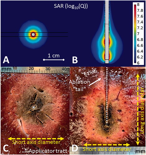
Figure 1. Simulated omni-directional applicator microwave specific absorption rate (SAR) cross-sectional (A) and longitudinal (B) plots above images of MWA experiments in ex vivo liver (C,D). The cross-sectional image (C) shows the applicator tract and short axis diameter while the longitudinal image (D) also shows the long axis diameter and the ablation ‘tail.’
To deliver sufficient power to ablate tissue, the small (typically < 1 mm) diameter microwave transmission lines within a MWA applicator are often operated at almost an order of magnitude higher power than they would be otherwise rated if exposed and cooled by ambient air. Therefore, almost all clinical MWA systems include a strategy for thermal management, without which the applicator shaft may heat sufficiently to cause unintended thermal ablation of tissue along its length or the applicator may face material failure [Citation11]. Most systems use circulating water while one uses compressed gas expansion [Citation12]. In addition to cooling the internal transmission line, active cooling of the MWA applicator internal components and shaft can cool the surrounding tissue, reducing the ‘tail’ of ablation zone and improving its sphericity. Another thermal management approach that has been used for lower frequency MWA systems is power pulsing, where applied power is turned on and off, so as to limit the peak temperature along the applicator shaft [Citation13].
When water cooling is used, current MWA systems differ in whether the cooling water encompasses the active antenna element or terminates and returns at some point proximal to the antenna. When surrounding the antenna, water (which has a high relative permittivity) acts as a dielectric load and enables the antenna to have a shorter physical length and maintain a stable impedance match even as the electrical properties of the surrounding tissue change during thermal ablation. Use of a shorter antenna length also contributes to improved sphericity of the resulting ablation zone [Citation14]. Directly cooling the active portion of the applicator may also reduce the chance of tissue getting charred/desiccated at very high temperatures and adhering to the applicator shaft, which can make post-ablation applicator removal more traumatic. Water, however, does create internal losses as microwave power is radiated through it and absorbed, which could result in a smaller fraction of the emitted power from being transferred to the surrounding tissue.
A MWA antenna’s emission pattern, ablation field, and impedance matching in tissue are typically used as benchmarks for assessing the merit of its engineering design [Citation15]. In clinical application, MWA applicators are compared and evaluated based on three main criteria:
Short-axis diameter – This is the maximal width of the thermal ablation zone measured perpendicular to the applicator shaft as shown in . This is often used to describe the maximum ablation zone size achievable by a particular applicator. Some clinical MWA applicators can achieve short axis diameters of approximately 4 cm in 5–10 minutes in ex vivo liver tissue, which has emerged as a de facto standard medium for evaluating ablation devices [Citation16].
Axial ratio – This is the ratio of the ablation zone short axis diameter (radial) to the long axis diameter (longitudinal). An ideal MWA applicator would have an axial ratio approaching unity where the ablation zone is a sphere. Spherical ablation zones afford simplified single-applicator treatment planning and are more likely to preserve more normal tissue adjacent to the applicator shaft. Some current MWA applicators are able to achieve axial ratios near 1.0 at some time and power combinations, while others exhibit axial ratios in the range 0.7 to 0.9 [Citation17].
Shaft diameter – The smaller the diameter of the applicator, the less invasive the treatment. Clinical MWA applicators range from 13-gauge (0.095”/2.4 mm diameter) to 17-gauge (0.058”/1.5 mm diameter) [Citation4]. Applicator diameter is also loosely correlated to stiffness and rigidity, a quality necessary for accurate applicator placement.
Furthermore, it is desirable to construct the applicator from materials that are echogenic, so the applicators can be readily visualized on ultrasound imaging and have minimal streak artifact (which can obscure visualization of the target lesion and/or surrounding critical structures) on CT imaging [Citation18]. MR compatibility may also be advantageous for the treatment of tumors only visible on MRI.
Conventional MWA limitations
All currently available MWA systems produce a roughly spherical, ellipsoid, or teardrop-shaped treatment zone which is centered on the applicator’s axis near the tip. This may not be universally suitable for treating tumors with irregular shapes or those located near critical anatomy [Citation4,Citation16]. To work around this design limitation, physicians often employ additional thermoprotective techniques such as fluid or gas dissection, endoluminal perfusion with cooling fluid (such as in the biliary or urinary collecting system), or balloon catheter interposition to displace at-risk tissue structures away from the expected treatment zone. While effective, these techniques increase the complexity of the procedure [Citation19,Citation20]. Failure of these techniques may also occur, resulting in non-target organ injury which may require additional emergent and extended medical care [Citation19,Citation20]. The presence of nearby heat sink effects from blood vessels or local distortion at tissue interfaces can also skew the size and shape of ablation zones in unpredictable ways [Citation21,Citation22]. Ultimately, because the extent of the treatment zone is unable to be definitively visualized by imaging in real-time, there is always some inherent degree of operator uncertainty in the treatment result. As a result of the increased power and associated inherent unpredictability of MWA relative to RFA, many operators who lack extensive experience with MWA devices tend to utilize this tumor ablation modality less frequently in practice for tumors located in smaller organs (such as kidney or adrenal gland) or in close proximity to sensitive anatomic structures due to the perceived risk for unintended collateral damage [Citation19]. Existing MWA systems optimized for large volume ablation are infrequently considered for treating very small tumors in sensitive glands such as the adrenal or thyroid, though site-specific applicators are under development [Citation23].
Directional MWA (DMWA) applicators
Overview
While there are no DMWA devices in current clinical use for minimally-invasive applications, some publications have reported on the design and proof-of-concept demonstration of DMWA applicators. McWilliams et al presented a water-cooled 2.45 GHz monopole antenna augmented with a hemi-cylindrical reflector, suitable for directing microwave power to a preferred radiation direction, approximately half of the angular expanse [Citation24]. Sebek et al adapted this design to demonstrate ablation in ex vivo tissue with a 2.5 mm diameter applicator [Citation25]. Pfannenstiel et al demonstrated proof-of-concept for a new 14 G DMWA applicator in an in vivo porcine liver model [Citation26]. Mohtashami et al presented an uncooled 7 GHz hybrid monopole-slot antenna with a directional radiation pattern [Citation27]. The technical feasibility of shaping directional ablation zones with a dipole antenna terminating two-wire transmission line was demonstrated by Mohtashami et al [Citation28]. Williams et al reported on a DMWA applicator designed for ablation of cardiac tissue for treatment of atrial fibrillation via a surgical approach [Citation29]. Biffi Gentili et al reported on a 434 MHz antenna with a reflector for creating directional mild therapy profiles [Citation30]. Directional ablation technologies employing other energy modalities including lasers [Citation31,Citation32] and catheter-based ultrasound [Citation33–35] have been developed and some are in clinical use.
Similar to existing omni-directional MWA applicators, DMWA applicators can be evaluated based on shaft diameter, however short-axis diameter and axial ratio metrics do not meaningfully describe the ablation zone shape. Additional criteria for comparison and evaluation of DMWA applicators include:
Forward ablation depth (df) – The maximal distance the ablation zone extends in the desired target (forward) direction measured perpendicular to the applicator as shown in . This measurement can be made from a cross section or longitudinal slice. For DMWA, care must be taken to slice experimental specimens and take measurements in the plane of maximal heating. Any slice not along the maximal plane will result in inaccurately small measurements – this differs from omni-directional ablation measurements where any longitudinal slice that follows the applicator tract will show equivalent ablation dimensions.
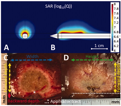
Figure 2. Simulated directional applicator microwave specific absorption rate (SAR) cross-sectional (A) and longitudinal (B) plots above images of DMWA experiments in ex vivo liver (C,D). The cross-sectional image (C) shows the applicator tract, forward ablation depth (df) (yellow dashed line), backward ablation depth (db) (red line), and ablation width (w) (blue dashed line) while the longitudinal image (D) shows forward ablation depth (df) (yellow dashed line) and ablation height (h) (green dashed line).
Backward ablation depth (db) – The maximal distance the ablation zone extends in the non-target (backward) direction measured perpendicular to the applicator. This measurement should be made from a cross sectional slice only to observe if the ablation zone extends further backward on either side of the applicator tract.
Directivity ratio (df/db)– The ratio of the forward ablation depth divided by the backward ablation depth. An ideal DMWA applicator would have db = 0, and thus an infinite directivity ratio.
Ablation width (w) – The maximum distance the ablation zone extends laterally. This measurement must be taken in the cross-sectional slice.
Ablation height (h) – The maximum distance the ablation zone extends from its distal end to its proximal end. This measurement must be taken in the longitudinal slice.
Shaft diameter – Similar to omni-directional applicators, diameter influences the invasiveness of the device which must be balanced with its rigidity and stiffness, which in-turn influences device usability.
New DMWA-Enabled clinical techniques
With DMWA applicators in their toolkit to complement conventional MWA devices, operators would have the ability to consider a broader range of treatment techniques and approaches with more degrees of freedom to shape ablation zones and target tumors located in difficult areas. DMWA-enabled techniques include:
‘Outside-in’ ablation
Rather than the ‘inside-out’ treatment approach used by current omni-directional applicators, DMWA enables an ‘outside-in’ approach which allows the physician to place the applicator alongside the tumor and direct energy toward the target and away from sensitive tissues (illustrated and shown in in vivo liver in ). DMWA may enhance the effectiveness or reduce the dependence on thermo-protective techniques and may enable MWA treatment of tumors in more challenging locations. An ‘outside-in’ approach may facilitate technically easier treatment of small lesions that are displaced within the surrounding tissue when an applicator is inserted nearby (such as small lung nodules that may move within the elastic lung tissue, making them difficult to pierce) while preserving more surrounding healthy tissue than omni-directional applicators. An ‘outside-in’ method potentially offers assurance of a treatment margin between the applicator and tumor, though it may provide less assurance of treatment margin on the opposite extent of the tumor. Finally, some tumors can spread, or ‘seed’ along needle tracts after direct puncture due to bleeding, steam release during tumor heating, or during withdrawal of the applicator for repositioning. Avoiding direct puncture of target tumors may therefore serve to reduce the risk of iatrogenic tumor seeding [Citation36].
Figure 3. Illustration of DMWA enabled ‘outside-in’ heating approach with an applicator positioned adjacent to and aiming toward the target next to image of ‘outside-in’ ablation experiment in in vivo porcine liver (3 A). Illustration of ‘directional bracketing’ ablation approach next to image of ‘directional bracketing’ ablation experiment in ex vivo bovine liver (3B). Illustration of DMWA ‘surface ablation’ approach for targets near the organ surface (e.g., subcapsular tumors) next to image of image of ‘surface ablation’ experiment in in vivo porcine liver (3 C). Illustration of ‘sector-sweep’ ablation approach to compensate for off-center applicator placement next to image of ‘sector-sweep’ ablation experiment in ex vivo bovine liver (3 D). Illustration of DMWA ‘offset ablation’ approach next to image of image of ‘offset ablation’ experiment in ex vivo bovine liver (3E). Illustration of ‘Combination omni-MWA + DMWA’ approach next to image of image of ‘Combination omni-MWA + DMWA’ ablation experiment in ex vivo bovine liver (3E). For all sub-images the yellow dashed lines indicate the direction of MW radiation.
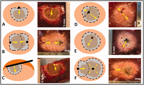
‘Directional bracketing’
Multiple DMWA applicators could be used to ‘bracket’ relatively larger tumors, with applicators positioned along the target periphery and radiating inwards, treating them with a composite ablation zone, and providing assurance of a clinical margin between the applicators and tumor (illustrated and shown in ex vivo liver in ). Use of multiple omni-directional applicators is already a common technique to treat larger tumors [Citation37], and a conceptually similar ‘no-touch’ bracketing technique has been described using multi-bipolar RFA for the purpose of reducing the risk of tumor seeding and thermal injury to non-target tissues near the treatment zone [Citation38,Citation39]. Recent studies suggest that sub-ablative heating of non-target tissue around the margins of the ablation zone may have pro-tumorigenic effects that could increase the likelihood of recurrent disease at the treatment zone margins, which adds rationale for the development of techniques that direct thermal ablative energy preferentially toward targeted tissue and away from surrounding, otherwise healthy organ parenchyma [Citation40,Citation41].
‘Surface ablation’
Because DMWA applicators radiate in a specific direction, they may be placed on the surface of a target organ or gland and heat a portion of it to ablative temperatures without penetrating it directly (illustrated and shown in ex vivo liver in ). While this may seem like only a subtle difference from the ‘outside-in’ method of treating tumors within an organ, a non-penetrating approach may enable minimally invasive treatment for a broader range of difficult to treat tumors. For example, small organs or glands may be difficult to pierce as they often tend to displace rather than be easily punctured by the applicator. Furthermore, the penetration of some glands, such as the adrenal gland, may severely damage them and create dangerous complications. Positioning a DMWA applicator alongside a gland, organ, or nerve could enable treatment of a shallow target zone within that structure without damaging the surrounding anatomy. This is conceptually similar to an approach proposed for microwave ablation treatment of cardiac arrhythmias [Citation29,Citation42].
‘Sector-sweep ablation’
If a DMWA applicator was inserted centrally into a tumor, it could be rotated to target multiple directions and sweep out a symmetric ablation zone similar in size and shape to the capability of existing omni-directional clinical applicators (shown in ex vivo liver in ). Although not as efficient as an omni-directional device for a 360-degree circumferential ablation in this setting, the ‘sector-sweep’ functionality would confer benefit in treating tumors with irregular shapes over smaller degrees of circumferential rotation. Furthermore, the directionality of this device would enable targeted retreatment of any regions of the tumor that may show viability on immediate post-treatment contrast-enhanced imaging. Using a ‘sector-sweep’ approach while varying generator power and time settings for treating different sectors of the tumor also has the potential to create targeted, asymmetric ablation zones for irregularly shaped tumors, or to compensate for inaccurate (off-center) placement of the applicator within an otherwise spherical-shaped tumor (illustrated in ). This approach would benefit from recent advances in treatment planning software programs that are able to map and overlay intended treatment zone margins to determine when and by what degree to rotate the applicator during treatment, as well as the specific thermal dose to be used for subsequent sector re-treatment if necessary, similar to technology that has been demonstrated for use with catheter-based ultrasound thermal ablation techniques [Citation43]. It would be important to image the treatment zone extent with the DMWA applicator in situ for this determination, and some new potential techniques for doing so are currently under development [Citation43–45].
‘Offset ablation’
The primary advantage of DMWA is minimizing or eliminating any backward heating and allowing better spatial control of the thermal ablation zone. In some situations, however, there may still be a need for some degree of backward heating, such as when challenging anatomy and limitations in imaging localization result in the insertion of a MWA applicator into a tumor in an off-center location. In this case, a higher power or longer duration DMWA procedure could develop some degree of thermal conduction in a backward direction, resulting in an approximately spherical ablation with its center offset from the applicator tract axis (illustrated and shown in ex vivo liver in ). The ‘offset’ ablation zone could have a forward to backward depth directivity ratio of approximately 2:1 compared to DMWA treatment performed under lower power or for shorter duration, with directivity ratios exceeding 15.
Combination Omni-MWA + DMWA
As a hybrid of multiple conventional applicator procedures and ‘directional bracketing,’ the use of a combination of directional and omni-directional applicators may also confer the ability to achieve large volume ablation zones, the shape of which could be sculpted to match more closely that of the target tumor (illustrated and shown in ex vivo liver in ). This may enable greater preservation of healthy tissue when treating large, but asymmetric tumors or enable a safer treatment of a large tumor where a portion of the tumor is near sensitive critical anatomy. When combined with emerging treatment planning and stereotactic/robotic ablation applicator placement approaches [Citation46], these techniques offer the opportunity for precise delivery of conformal thermal ablation profiles.
In summary, DMWA can complement existing MWA technologies, adding more options to contour/shape ablation zones as well as enabling a no touch/non-penetrative approach for small, localized lesions.
Potential DMWA clinical applications
Liver
A meaningful minority of liver tumors (approximately 20–50%) are located near critical structures at risk for collateral damage from thermal injury during treatment. As previously discussed, some of these critical structures, such as parts of the diaphragm, colon, small bowel, or stomach, can be insulated or physically separated from the thermal ablation zone by thermo-protective techniques such as hydro- or gas (a.k.a. ‘pneumo-') dissection, or catheter-balloon displacement [Citation19,Citation20]. However, the passive diffusion of fluid or gas, or the potential inadvertent movement of balloons within the abdominal cavity during patient respiration may limit the reliability of these protective techniques [Citation19,Citation20]. Furthermore other fixed vulnerable structures, such as the bile ducts or gall bladder, cannot be reliably insulated or separated from a nearby tumor by thermo-protective displacement techniques and physicians cope with the lack of directionality of commercially available applicators by orienting the insertion such that the tip ‘points at’ the at risk structure because the thermal ablation zone typically extends only a few millimeters or less past the distal tip of the applicator [Citation20]. For technical and anatomic reasons, however, a specific percutaneous access approach in the most favorable direction is not always possible. The use of a DMWA applicator may enhance the effectiveness of or reduce dependence on thermo-protective techniques to preserve adjacent vital structures from collateral injury or enable treatment of liver tumors in difficult locations that otherwise could not be thermally isolated.
Kidney
The kidney is a much smaller target site than liver with proximity to many more thermally sensitive critical structures such as the bowel, pancreas, genitofemoral nerve, renal collecting system and ureter [Citation47]. Potential consequences of excessive thermal injury include pelvicalyceal/ureteric stricture, bowel perforation/stricture, abscess/fistula formation, urine leakage, and neuropathy [Citation19]. Currently, radiofrequency ablation (RFA) and cryoablation are the two most commonly used ablation techniques in the kidney [Citation47], though MWA may also be used successfully in a large proportion of cases where tumors are located in exophytic or non-central locations [Citation48–50]. This is likely because RFA is associated with a smaller active heating core than MWA, and the relatively larger conductive zone of heating can be adequately contained/insulated by perinephric fat (the so called ‘oven effect’) [Citation51]. Cryoablation has been widely utilized to date for kidney tumor ablation because the low-density ice ball that forms during treatment can be visualized and monitored essentially in real-time by CT imaging during treatment, and this visualization of the ablation zone size in real-time empowers the operator to terminate the treatment when the ablation zone achieves sufficient size, thereby reducing the risk of excessive thermal injury to non-target structures that can occur from the inability to similarly visualize the extent of the treatment zone when using heat-based thermal ablation modalities. However, the advent of DMWA may provide the necessary spatial control of the thermal ablation zone to effectively treat renal tumors in even more central locations while maximally preserving renal function by customizing the ablation zone size/shape and minimizing nephron loss.
Lung
The lung is a common site for tumor metastasis, but only about 30% of lung cancer patients are considered surgical candidates due to co-morbidities and advanced age [Citation52]. Like liver and kidney, lung is also a highly vascularized organ, but it is also aerated, which reduces electrical and thermal conductivity and makes heat-based thermal ablation challenging [Citation53]. This low electrical conductivity reduces the rate of heating achievable by MWA, but also enables microwave energy to penetrate further than in other solid organs where the tissue has higher water density [Citation6]. Lung tumors, however, are composed of solid tissue with higher water content than surrounding lung tissue. As a result, lung tumors have electrical and thermal properties that are more favorable to tissue heating than surrounding aerated lung tissue, which suggests that MWA may have the ability to propagate further through healthy lung tissue while selectively heating tumor tissue with greater intensity [Citation6]. Conventional MWA has been applied successful in lung [Citation52], though DMWA may provide the spatial control necessary to provide treatment of tumors near mediastinal structures such as the heart, esophagus, or major airways.
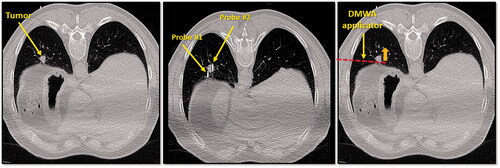
With respect to lung tumor ablation, DMWA’s most significant advantage may be its ability to utilize an ‘outside-in’ treatment approach. Lung tumors that are solid or semi-solid may be displaced within the elastic lung parenchyma while attempting to puncture them with a rigid treatment applicator, making precise intra-tumoral placement of a conventional thermal ablation applicator challenging. Conversely, placing a DMWA applicator beside a lung tumor and aiming toward it may be technically preferable and provide better control of treatment zone margins. Incorporating directional MWA capabilities into flexible applicators suitable for bronchoscopic-guided delivery and placement into more centrally located target tumors may further broaden the use of this technology for treatment in lung, although it is recognized that precise directional control of long, flexible catheter-based applicators may be technically challenging [Citation54–56]. and show examples of clinical cases that could benefit from DMWA techniques.
Figure 4. CT image of 1.3 cm para-mediastinal tumor (yellow arrow) adjacent to esophagus in a patient at high risk for surgery (left image). CT image of an induced pneumothorax and ‘chopstick’ technique to treat the tumor with existing cryoablation probes (middle image). Illustration of hypothetical DMWA applicator placement (red dashed line) and direction of microwave emission (orange arrow) to treat the tumor and avoid the esophagus (right image).
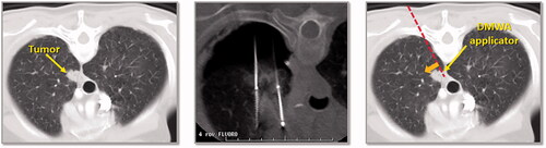
Figure 5. CT image of 1.6 cm lower lobe lung tumor abutting the diaphragm (left image). The challenge in this case is successfully ‘skewering’ the tumor with the ablation applicator without lesion ‘roll-off’ or injury to the diaphragm. CT image of ‘chopstick’ technique to enable treatment of this with existing cryoablation probes (middle image). Two cryoprobes are used; cryoprobe #1 is advanced alongside the tumor and a ‘stick freeze’ is performed to adhere the nodule and enable puncture with cryoprobe #2. Cryoprobe #1 is then thawed and repositioned in the nodule in parallel with probe #2. Illustration of hypothetical DMWA applicator ‘outside-in’ placement (red dashed line) and direction of aim (orange arrow) to treat the tumor and avoid the diaphragm (left image).
Bone
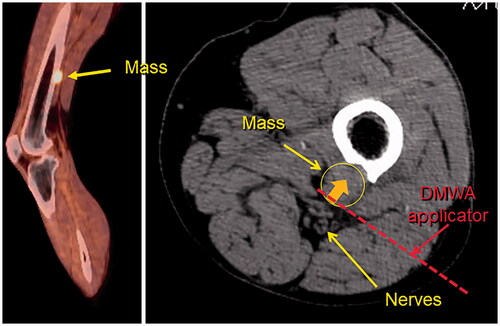
Similar to lung, bone is a common site of cancer metastasis. Should cancer develop in a vertebral body in the spine, or a weight-bearing bone, pain, pathologic fracture, or neurological problems may result. Possible treatments for primary bone cancer include surgery, chemotherapy, and radiation therapy. However, none of these typical treatment options may be possible, effective, tolerable, or rapid-enough in effect for a patient who has progressed to late-stage metastatic cancer. Of thermal ablation options, RFA would have reduced heating ability in high-impedance bone tissues while cryoablation would require relatively prolonged treatment times, especially at the end of treatment to allow ample time for the space-occupying ice to completely thaw and enable backfill of the treatment zone with cementoplasty, which is often performed to augment structural stability [Citation57]. The use of high intensity ultrasound has also been proposed for treatment of tumors in bone, as the high acoustic absorption coefficient of bone helps to confine the treatment zone primarily to the target, thereby protecting adjacent critical structures [Citation58,Citation59]. While the application of conventional omni-directional MWA in bone has not been studied in detail, some groups have shown feasibility of its clinical use but with broad application likely limited by concerns about the ability to provide sufficient spatial control of the treatment zone, especially when being used in the spine near critical anatomy such as the spinal cord or other nerves [Citation57,Citation60]. Similar to treatment of lung tumors, DMWA may have significant advantages in its ability to employ an ‘outside-in’ or ‘surface ablation’ approach to treat bone tumors which are otherwise difficult to access and target directly. shows an example of a bone tumor near a neurovascular nerve bundle that may benefit from the use of DMWA techniques.
Figure 6. Sagittal fused PET/CT image (left) and axial non-contrast CT image (right) of melanoma metastasis to left femur abutting tibial and peroneal nerves. Illustration of hypothetical DMWA applicator placement (red dotted line) and direction of microwave emission (orange arrow) to treat the tumor and avoid injury to the neurovascular bundle.
Glands
Benign, but functional tumors in glands, such as the adrenal or thyroid, can result in unregulated hormone production that leads to a variety of side effects including hypertension, irregular or rapid heartbeat, and weight loss, among many others [Citation61]. Current treatment of these conditions includes surgical resection which often necessitates chronic replacement medication, or simply management of the symptoms with chronic medication. Although radiofrequency and microwave ablation devices have been used for treating adrenal tumors, current thermal ablation technologies optimized for large volume ablation in vascular organs do not provide tight spatial control to create localized ablation of small (∼1cm3) targets in glands such as the adrenal or thyroid which are not only delicate and susceptible to mechanical and thermal damage themselves, but are also in close proximity to many critical structures [Citation23,Citation61]. Thermal heating of the adrenal medulla during ablation may lead to hypertensive crisis due to catecholamine release. Such treatments are usually performed under general anesthesia with arterial line placement for continuous hemodynamic monitoring and intravenous calcium channel blocker drips to titrate blood pressure and compensate for hypertensive surges when they occur during heating [Citation62]. DMWA however, has demonstrated an ability to provide precise spatial control while creating approximately 1 cm3 lesions in an in vivo liver model [Citation26] and has been used in an in vivo study to ablate porcine adrenal glands using a ‘surface ablation’ technique to minimize collateral damage to the adjacent normal adrenal cortex [Citation61].
Other DMWA applications
Though modifications to the traditional needle-based DMWA applicator form may be necessary, the unique spatial control provided by DMWA systems may have potential to expand minimally invasive treatment to a range of other indications outside of oncology. Though speculative in nature, some examples may include: DMWA neurotomy targeting specific nerves to block the signals that cause chronic pain in the back, neck, or joints; ‘outside-in’ ablation of dense uterine fibroids that are the source of heavy menstrual bleeding and pelvic pain or pressure; targeted debulking of an enlarged prostate gland for symptom relief of benign prostate hyperplasia (BPH) or prostate cancer; and endoscopically delivered DMWA to ablate esophageal varices [Citation25].
DMWA current limitations
Currently, no DMWA applicators are available clinically for medical use, and the experimental results from DMWA applicators under development have utilized applied time and power combinations specifically selected to minimize backward heating, which have resulted in overall ablation volumes that are substantially smaller than existing omni-directional devices [Citation26]. Combined use of DMWA applicators with omni-directional applicators, or in conjunction with thermal accelerants, may provide added degrees of freedom for clinicians to sculpt customized ablation zone profiles [Citation63]. Though further study of the ability to create larger ‘directional-bracketing’ or ‘sector-sweep’ composite ablation zones is necessary, omni-directional MWA applicators may still be best suited for delivering large volume ablation zones in short times where precise spatial control is not a significant concern. Further, the smallest diameter DMWA device that has been reported in the literature is 14 G, and while comparable in size to some conventional MWA applicators in current clinical use, smaller diameter applicators may offer advantages in some sites. Additional animal studies will be necessary to investigate the in vivo performance of directional applicators across a broader range of power levels and tissue types prior to more widespread experimental use in humans.
Conclusion
DMWA’s ability to provide precise spatial control of the thermal ablation zone may be advantageous for tumor ablation in many challenging cases to complement the strengths of existing MWA systems, as well as for expanding clinical applications of thermal ablation as a minimally-invasive treatment option outside the realm of interventional oncology. With further technical development and translation of this technology, it is anticipated that DMWA may be particularly well suited for non-penetrative treatment of small-targets – structures which are currently considered to be high-risk for treatment using existing omnidirectional MWA systems. Although great progress has been made since the inception of DMWA that offers exciting potential for its use in medical practice, further development and evaluation of this technology in the clinical setting is warranted to determine the full extent of its potential benefits in practice.
Disclosure statement
Austin Pfannenstiel discloses being the founder of Precision Microwave, Inc. and an inventor on patents owned and licensed by Precision Microwave. Damian E. Dupuy discloses the receipt of licensing fees, royalty, and consulting fees, equity ownership in Theromics, Inc., being an inventor on patents, and 2021 SIO annual committee membership. Punit Prakash discloses being the subaward-PI on NSF grant IIP 1951186 and an inventor on patents owned and licensed by Precision Microwave. The authors alone are responsible for the content and writing of the paper.
Additional information
Funding
References
- Kok HP, Cressman ENK, Ceelen W, et al. Heating technology for malignant tumors: a review. Int J Hyperthermia. 2020;37(1):711–741.
- Lawrenz JM, Ilaslan H, Lietman SA, et al. Minimally invasive techniques for pain palliation in extraspinal bone metastases: a review of conventional methods and cryoablation. Curr Orthop Pract. 2016;27(5):547–552.
- Hayek G, Kastler B. Interventional radiology for treatment of bone metastases. Cancer Radiother. 2020;24(5):374–378.
- Ward RC, Healey TT, Dupuy DE. Microwave ablation devices for interventional oncology. Expert Rev Med Devices. 2013;10(2):225–238.
- Ryan TP, Brace CL. Interstitial microwave treatment for cancer: historical basis and current techniques in antenna design and performance. Int J Hyperthermia. 2017;33(1):3–14.
- Brace CL. Radiofrequency and microwave ablation of the liver, lung, kidney, and bone: What are the differences? Curr Probl Diagn Radiol. 2009;38(3):135–143.
- Ruiter SJS, Heerink WJ, de Jong KP. Liver microwave ablation: a systematic review of various FDA-approved systems. Eur Radiol. 2019;29(8):4026–4035.
- Mohtashami Y, Luyen H, Sawicki JF, et al. Tools for attacking tumors: Performance comparison of triaxial, choke dipole, and Balun-Free Base-Fed monopole antennas for microwave ablation. IEEE Antennas Propag Mag. 2018;60(6):52–57.
- Fallahi H, Prakash P. Antenna designs for microwave tissue ablation. Crit Rev Biomed Eng. 2018;46(6):495–521.
- Huang H, Zhang L, Moser MAJ, et al. A review of antenna designs for percutaneous microwave ablation. Phys Med. 2021;84:254–264.
- Kuang M, Lu MD, Xie XY, et al. Liver cancer: increased microwave delivery to ablation zone with cooled-shaft antenna–experimental and clinical studies. Radiology. 2007;242(3):914–924.
- Lubner MG, Hinshaw JL, Andreano A, et al. High-powered microwave ablation with a small-gauge, gas-cooled antenna: initial ex vivo and in vivo results. J Vasc Interv Radiol JVIR. 2012;23(3):405–411.
- Weiss J, Winkelmann MT, Gohla G, et al. MR-guided microwave ablation in hepatic malignancies: clinical experiences from 50 procedures. Int J Hyperthermia. 2020; Jan 137(1):349–355.
- Fallahi H, Clausing D, Shahzad A, et al. Microwave antennas for thermal ablation of benign adrenal adenomas. Biomed Phys Eng Express. 2019;5(2):025044.
- Etoz S, Brace CL. Analysis of microwave ablation antenna optimization techniques. Int J RF Microw Comput Aided Eng. 2018;28(3):e21224.
- Hoffmann R, Rempp H, Erhard L, et al. Comparison of four microwave ablation devices: an experimental study in ex vivo bovine liver. Radiology. 2013;268(1):89–97.
- Alonzo M, Bos A, Bennett S, et al. The Emprint™ Ablation System with Thermosphere™ Technology: one of the Newer Next-Generation Microwave Ablation Technologies. Semin Intervent Radiol. 2015;32(4):335–338.
- Gillies DJ, Rodgers JR, Gyacskov I, Roy P, et al. Deep learning segmentation of general interventional tools in two-dimensional ultrasound images. Med Phys. 2020;47(10):4956–4970.
- Garnon J, Cazzato RL, Caudrelier J, et al. Adjunctive thermoprotection during percutaneous thermal ablation procedures: Review of current techniques. Cardiovasc Intervent Radiol. 2019;42(3):344–357.
- Smirniotopoulos J, Cheng W, Krohmer S, et al. Interventional oncology: Keeping out of trouble in ablation techniques. Tech Vasc Interv Radiol. 2018;21(4):223–227.
- Loriaud A, Denys A, Seror O, et al. Hepatocellular carcinoma abutting large vessels: comparison of four percutaneous ablation systems. Int J Hyperthermia. 2018;34(8):1171–1178.
- Deshazer G, Merck D, Hagmann M, et al. Physical modeling of microwave ablation zone clinical margin variance. Med Phys. 2016;43(4):1764.
- Donlon P, Dennedy MC. Thermal ablation in adrenal disorders: a discussion of the technology, the clinical evidence and the future. Curr Opin Endocrinol Diabetes Obes. 2021;28(3):291–302.
- McWilliams BT, Schnell EE, Curto S, et al. A directional interstitial antenna for microwave tissue ablation: Theoretical and experimental Investigation. IEEE Trans Biomed Eng. 2015;62(9):2144–2150.
- Sebek J, Curto S, Eaton-Evans J, et al. Feasibility assessment of microwave ablation for treating esophageal varices. J Med Devices. 2017; Jul 1811(3):031013–031013–8.
- Pfannenstiel A, Sebek J, Fallahi H, et al. Directional microwave ablation: Experimental evaluation of a 2.45-GHz applicator in Ex Vivo and In Vivo Liver. J Vasc Interv Radiol. 2020;31(7):1170–1177.e2.
- Mohtashami Y, Hagness SC, Behdad N. A hybrid slot/monopole antenna with directional heating patterns for microwave ablation. IEEE Trans Antennas Propagat. 2017;65(8):3889–3896.
- Mohtashami Y, Luyen H, Hagness SC, et al. Non-coaxial-based microwave ablation antennas for creating symmetric and asymmetric coagulation zones. J Appl Phys. 2018;123(21):214903.
- Williams MR, Argenziano M, Oz MC. Microwave ablation for surgical treatment of atrial fibrillation. Semin Thorac Cardiovasc Surg. 2002;14(3):232–237.
- Biffi Gentili G, Gori F, Lachi L, et al. A dipole-type intracavitary hyperthermic applicator with a metallic reflector: experiments and theoretical analysis. Int J Hyperthermia. 1994;10(2):175–187.
- Sloan AE, Ahluwalia MS, Valerio-Pascua J, et al. Results of the NeuroBlate system first-in-humans phase I clinical trial for recurrent glioblastoma: clinical article. J Neurosurg. 2013;118(6):1202–1219.
- Patel NV, Mian M, Stafford RJ, et al. Laser interstitial thermal therapy technology, physics of magnetic resonance imaging thermometry, and technical considerations for proper catheter placement during magnetic resonance Imaging-Guided laser interstitial thermal therapy. Neurosurgery. 2016;79(Suppl 1):S8–S16.
- Galgano SJ, Planz VB, Arora S, et al. MR-Guided High-Intensity directional ultrasound ablation of prostate cancer. Curr Urol Rep. 2021;22(1):3.
- Salgaonkar VA, Diederich CJ. Catheter-based ultrasound technology for image-guided thermal therapy: current technology and applications. Int J Hyperthermia. 2015;31(2):203–215.
- Ross AB, Diederich CJ, Nau WH, et al. Highly directional transurethral ultrasound applicators with rotational control for MRI-guided prostatic thermal therapy. Phys Med Biol. 2004;49(2):189–204.
- Patel PA, Ingram L, Wilson IDC, et al. No-touch wedge ablation technique of microwave ablation for the treatment of subcapsular tumors in the liver. J Vasc Interv Radiol. 2013;24(8):1257–1262.
- Haemmerich D, Lee FT. Multiple applicator approaches for radiofrequency and microwave ablation. Int J Hyperthermia. 2005;21(2):93–106.
- Seror O, N’Kontchou G, Nault J-C, et al. Hepatocellular carcinoma within milan criteria: No-Touch multibipolar radiofrequency ablation for treatment—long-term results. Radiology. 2016;280(2):611–621.
- Petit A, Hocquelet A, N'kontchou G, et al. No-Touch multi-bipolar radiofrequency ablation for the treatment of subcapsular hepatocellular Carcinoma ≤ 5 cm Not Puncturable via the Non-tumorous Liver Parenchyma. Cardiovasc Intervent Radiol. 2020;43(2):273–283.
- Velez E, Goldberg SN, Kumar G, et al. Hepatic thermal ablation: Effect of device and heating parameters on local tissue reactions and distant tumor growth. Radiology. 2016;281(3):782–792. Dec
- Markezana A, Ahmed M, Kumar G, et al. Moderate hyperthermic heating encountered during thermal ablation increases tumor cell activity. Int J Hyperthermia. 2020;37(1):119–129.
- Williams MR, Knaut M, Bérubé D, et al. Application of microwave energy in cardiac tissue ablation: from in vitro analyses to clinical use. Ann Thorac Surg. 2002;74(5):1500–1505.
- Wang D, Adams MS, Jones PD, et al. High contrast ultrasonic method with multi-spatiotemporal compounding for monitoring catheter-based ultrasound thermal therapy: Development and ex vivo evaluations. IEEE Trans Biomed Eng. 2021;68(10):3131–3141.
- Abbass MA, Ahmad SA, Mahalingam N, et al. In vivo ultrasound thermal ablation control using echo decorrelation imaging in rabbit liver and VX2 tumor. PloS One. 2019;14(12):e0226001.
- Wu P-H, Bedoya M, White J, et al. Feature-based automated segmentation of ablation zones by fuzzy c-mean clustering during low-dose computed tomography. Med Phys. 20201;48(2):703–714.
- Lachenmayer A, Tinguely P, Maurer MH, et al. Stereotactic image-guided microwave ablation of hepatocellular carcinoma using a computer-assisted navigation system. Liver Int. 2019;39(10):1975–1985.
- Kim KR, Thomas S. Complications of Image-Guided thermal ablation of liver and kidney neoplasms. Semin Intervent Radiol. 2014;31(2):138–148.
- Cornelis FH, Marcelin C, Bernhard J-C. Microwave ablation of renal tumors: a narrative review of technical considerations and clinical results. Diagn Interv Imaging. 2017;98(4):287–297.
- Filippiadis DK, Gkizas C, Chrysofos M, et al. Percutaneous microwave ablation of renal cell carcinoma using a high power microwave system: focus upon safety and efficacy. Int J Hyperthermia. 2018;34(7):1077–1081.
- De Cobelli F, Papa M, Panzeri M, et al. Percutaneous microwave ablation versus cryoablation in the treatment of T1a renal tumors. Cardiovasc Intervent Radiol. 2020;43(1):76–83.
- Liu Z, Ahmed M, Weinstein Y, et al. Characterization of the RF ablation-induced “oven effect”: the importance of background tissue thermal conductivity on tissue heating. Int J Hyperth off J Eur Soc Hyperthermic Oncol North Am Hyperth Group. 2006;22(4):327–342.
- Sidoff L, Dupuy DE. Clinical experiences with microwave thermal ablation of lung malignancies. Int J Hyperthermia. 2017;33(1):25–33.
- Sebek J, Bortel R, Prakash P. Broadband lung dielectric properties over the ablative temperature range: Experimental measurements and parametric models. Med Phys. 2019;46(10):4291–4303.
- Pfannenstiel A, Keast T, Kramer S, et al. Flexible microwave ablation applicator for the treatment of pulmonary malignancies. In: SPIE 10066 Energy-based Treatment of Tissue and Assessment [Internet]. 2017 [cited 2017 Apr 10]. p. 100660M-1-100660M – 13. Available from: http://dx.doi.org/10.1117/12.2255504.
- Sebek J, Kramer S, Rocha R, et al. Bronchoscopically delivered microwave ablation in an in vivo porcine lung model. ERJ Open Res. 2020;6(4):00146-2020.
- Yuan H-B, Wang X-Y, Sun J-Y, et al. Flexible bronchoscopy-guided microwave ablation in peripheral porcine lung: a new minimally-invasive ablation. Transl Lung Cancer Res. 2019;8(6):787–796.
- Kastler A, Alnassan H, Aubry S, et al. Microwave thermal ablation of spinal metastatic bone tumors. J Vasc Interv Radiol. 2014;25(9):1470–1475.
- Scott SJ, Prakash P, Salgaonkar V, et al. Approaches for modelling interstitial ultrasound ablation of tumours within or adjacent to bone: theoretical and experimental evaluations. Int J Hyperthermia. 2013;29(7):629–642.
- Scott SJ, Salgaonkar V, Prakash P, et al. Interstitial ultrasound ablation of vertebral and paraspinal tumours: parametric and patient-specific simulations. Int J Hyperth off J Eur Soc Hyperthermic Oncol North Am Hyperth Group. 2014;30(4):228–244.
- Dupuy DE, Hong R, Oliver B, et al. Radiofrequency ablation of spinal tumors: temperature distribution in the spinal canal. AJR Am J Roentgenol. 2000;175(5):1263–1266.
- Donlon PT, Fallahi H, Beard WL, et al. Using microwave thermal ablation to develop a subtotal, cortical-sparing approach to the management of primary aldosteronism. Int J Hyperthermia. 2019;36(1):905–914.
- Fintelmann FJ, Tuncali K, Puchner S, et al. Catecholamine surge during Image-Guided ablation of adrenal gland metastases: Predictors, consequences, and recommendations for management. J Vasc Interv Radiol JVIR. 2016;27(3):395–402.
- Maxwell AWP, Park WKC, Baird GL, et al. Adjuvant thermal accelerant gel use increases microwave ablation zone temperature in porcine liver as measured by MR thermometry. J Vasc Interv Radiol JVIR. 2020;31(8):1357–1364.