
Abstract
The usage of high strength steel (HSS) is steadily increasing, primarily driven by the pursuit of weight reduction, leading to a subsequent decrease in greenhouse gas emissions. This paper investigates the impact of various post-weld heat treatment (PWHT) temperatures of 525 °C, 550 °C and 575 °C with a holding time of 2 h on both the microstructure and mechanical properties of weld metal produced using a HSS metal cored wire. The investigation reveals that PWHT does not significantly alter strength but has a more pronounced influence on toughness. The as-welded condition exhibited the highest toughness. Among the samples subjected to the PWHT, the one treated at 575 °C showed the highest impact energy, reaching 69 J at −60 °C. This outcome is attributed to the increased presence of acicular ferrite in the microstructure, surpassing that of samples subjected to PWHT at different temperatures.
Introduction
Weight reduction, especially in industries like automotive manufacturing, holds the potential to increase payload capacity, resulting in reduced fuel consumption and lower greenhouse gas emissions [Citation1,Citation2]. To attain lighter yet robust structures, HSS with yield strengths above 600 MPa are indispensable. HSS finds extensive applications in bridges, buildings, storage tanks, cranes, pipelines, offshore structures and transportation vehicles. The primary advantage of choosing HSS lies in its ability to withstand higher stresses and facilitate reduced dimensions, harnessing the benefits of its superior strength concerning the yield criterion [Citation2–5].
Common welding methods can be used for welding HSS; however, they require more care and attention than when welding lower strength steels. The primary concern in welding HSS is the low toughness of the weld metal and HAZ. It is known that an increase in strength is frequently accompanied by a loss in toughness, particularly at low temperatures. This is because plastic deformation, which is the major energy absorption mechanism during fracture, becomes more difficult as the strength increases [Citation6]. Susceptibility to cold cracking increases when welding HSS due to the presence of hard, potentially brittle microstructures, often martensite, in combination with hydrogen and tensile residual stresses.
To mitigate the risk of cold cracking and improve mechanical properties, several precautions can be adopted. Preheating the weld, controlling heat input, interpass temperature, using low-hydrogen filler materials, and employing post-weld heat treatment (PWHT) are effective measures. These strategies aim to reduce the likelihood of cold cracking and enhance the overall weld integrity and performance [Citation7–9].
The main advantages of PWHT are twofold: a significant reduction in tensile residual stresses and, to a lesser extent, tempering of the heat affected zone and weld metal microstructures. This reduction in residual stresses and tempering improves the weld’s integrity by decreasing the likelihood of fracture caused by cold cracking [Citation10,Citation11]. Due to these benefits, various codes and specifications such as the American Society of Mechanical Engineers (ASME) boiler and pressure vessel code, mandate PWHT for specific welded structures, such as pressure vessels and offshore platforms. The requirement for PWHT varies depending on the type and thickness of the welded joint. For example, ASME requires PWHT for welded joints over 38 mm nominal thickness in pressure vessels constructed of carbon-manganese steels. The standard specifies a holding temperature of 650 °C for a minimum holding time of 1 h per 25 mm thickness [Citation12]. Similarly, the BS EN13445 standard dictates PWHT for joints over 35 mm thick [Citation13]. Steel manufacturers advise conducting PWHT at temperatures below the steel’s original tempering temperature, established during its manufacture. This recommended PWHT temperature typically ranges from 30 to 60 °C lower than the steel’s tempering temperature, which generally falls between 520 °C and 580 °C. This practice ensures that steel retains its intended mechanical properties and microstructure integrity after PWHT.
It has been observed that PWHT can lead to various effects on the properties, especially toughness, of the weldment. The outcome depends on factors such as the chemical composition of the steel, the welding procedure used, and the specific PWHT time and temperature employed [Citation14]. Kalyankar and Chudasama [Citation15] conducted a comprehensive review on different heat treatment techniques after welding and their effects on pressure vessel steels. The conclusions drawn from this review emphasize the benefits of PWHT in improving toughness, reducing residual stresses and enhancing corrosion resistance. However, it is also noted that PWHT may have potential negative impacts on tensile strength and base metal properties. Therefore, selecting appropriate PWHT parameters becomes crucial to achieve the desired mechanical properties without compromising the overall performance of welded structures.
Jorge et al. [Citation16] investigated the effects of PWHT at 600 °C for 2 h on extra high strength steel (HSS) weld metals for applications in mooring equipment. Results showed that the PWHTed weld metals exceeded the minimum requirements for the steel plate in mechanical properties. Notably, impact toughness values were found to surpass the required standards, even at −60 °C. This indicates that the weld metal, following PWHT, exhibits robust mechanical strength and impact toughness, making it suitable for critical mooring system applications. The study by Alipooramirabad et al. [Citation10] investigates the effects of PWHT on the microstructural changes and mechanical properties of API 5L X70 high strength low alloy steel welds. PWHT significantly reduced residual stresses and altered the microstructure, improving ductility while slightly reducing yield and tensile strength.
As PWHT of large steel assemblies is an expensive process, owing to the long hold times and slow heating and cooling rates involved, and also due to the high cost of down-time, particularly where PWHT follows the repair of an existing fabrication, it is therefore greatly desired to obtain detailed knowledge and understanding of the PWHT process and its parameters to be sustainable and productive. In PWHT of steels holding temperature and time are the two most important parameters that would influence the microstructure and mechanical properties of the weld under treatment.
Research on PWHT of HSS all-weld metals, excluding the effect of dilution with the base metal, remains insufficiently explored. Most studies on the PWHT of HSS welds have used solid wire. However, with the increasing utilization of tubular wires, particularly metal cored wires, there is a significant need to deepen our understanding of PWHT processes for welds made using metal cored wires. Thus, this paper aims to provide comprehensive insights into how different PWHT holding temperatures at a holding time of 2 h influence the microstructure and mechanical properties of HSS weld metal. This investigation specifically focuses on welds produced using an HSS metal cored wire containing 2% Ni.
Experiment
Materials and welding
The study was carried out by using a 1.2 mm diameter HSS metal cored wire with a specified minimum yield strength of 690 MPa. S355 steel in dimensions 400 × 200 × 20 mm was used as the base metal. Typical chemical composition of the all-weld metal of the wire can be found in . The welding was performed by a Fronius TPS 500i which was mounted on a high-precision positioning robot ABB IRB 2600/IRBP 300L. The welding was performed in a flat position. Welding parameters were selected in order to get similar weld profiles and number of passes while keeping energy input at approximately 1 kJ/mm by welding current 250 A, voltage 25 V and speed of 40 cm/min. The weld metal was shielded by Nison 18 gas containing 82% Ar and 18% CO2 with gas flow of 15.0 l/min. The minimum preheat temperature of 120 °C and maximum inter-pass temperature of 150 °C was used for welding the samples. As the aim in this investigation was focused only on all-weld metal analysis buttering with the same consumable in thickness of around 5 mm was employed to prevent dilution with the base metal. and show the joint configuration and the welding setup used in this study, respectively.
Figure 1. The joint configuration.
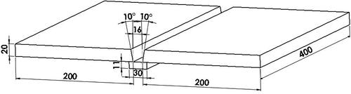
Figure 2. Welding setup.
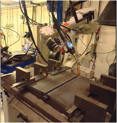
Table 1. Typical all-weld-metal chemical composition of the welding wire used (% by weight).
Post-weld heat treatment
Three different PWHT were conducted using a Rohde induction furnace at temperatures of 525 °C, 550 °C and 575 °C, each with a holding time of two hours. The treatments involved a heating rate of 150 °C/h and a cooling rate of 80 °C/h. The samples were extracted from the furnace when the temperature reached 100 °C. The as-welded and PWHT samples were coded as shown in . The PWHT parameters were chosen to investigate the widest spectrum of temperatures typically applied in the PWHT of HSS welds, ensuring that the maximum temperature remained below the tempering temperature of the most utilized HSS grades. Additionally, the PWHT parameters recommended by the most recognized standards were considered. It is important to highlight that while recommendations often pertain to the PWHT of base metals, this study exclusively investigates all weld metals.
Table 2. Samples used for experiments.
Microstructural, mechanical and chemical analysis
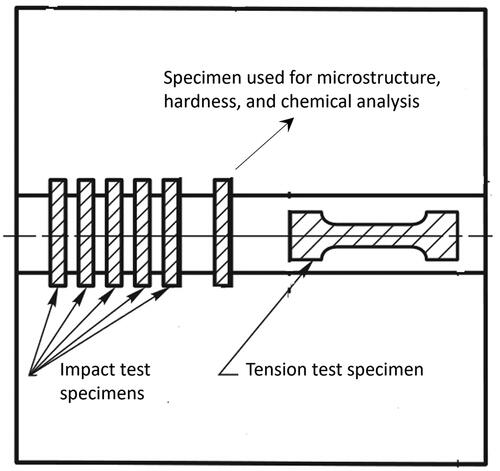
Samples for microscopy, hardness, chemical analysis and mechanical testing were extracted from the as welded and PWHT samples. Schematic illustrations of samples extracted are shown in . Specimens were taken from mid-thickness of the weld.
Figure 3. Test plate showing location of specimens used for analysis and mechanical tests.
The microstructures of both as-welded and post-weld heat-treated samples were investigated using stereoscopic and light optical microscopes. To conduct the examination, the samples were first cut, hot-mounted and then polished. A 3% nital solution was used as the etchant. An advanced optical microscope (Nikon Epiphot, PT 15, Lake Bluff, IL) was employed to capture micrographs from two specific positions: P1 (the top bead) and P2 (the middle of the weld) (see ).
Position 1 allowed for the examination of the cap weld unaffected by subsequent beads. On the other hand, position 2 facilitated the study of the region that had been re-heated and melted multiple times, offering an understanding of the weld’s response to repeated thermal cycles. Additionally, position 2 served as a representative area from which tensile and Charpy samples were extracted.
All-weld metal longitudinal tensile test was performed at room temperature while Charpy V-Notch (CVN) was done at temperatures −40 °C and −60 °C. Three samples at each temperature were tested and the average was reported as the impact energy. Tests were performed according to ISO 15792-1:2020.
Microhardness measurements along the weld from top to bottom, dashed line L shown in , was done using HV10 on cross sections that were cut, polished and mounted, by hardness testing machine Qness Q30A+. The distance between adjacent measurement points in microhardness measurements was 0.1 mm. XRF analysis was performed by Hitachi X-MET8000 handheld XRF (X-ray fluorescence) to investigate the possible inclusions in the welds. Optical emission spectroscopy was also done to get the chemical analysis for all samples.
Results and discussion
Mechanical properties
Tensile and impact toughness values are presented in . The result for hardness measurement is illustrated in . The mechanical values specified by EN ISO and AWS of the consumable used are also added for comparison.
Figure 4. Hardness plots starting in the last bead showing the effect of increasing of PWHT temperature.
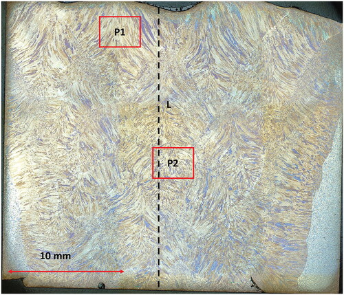
Table 3. Mechanical strength and impact toughness results.
Higher strength, especially higher tensile strength was observed after PWHT compared to as-welds. In the other hand, lower impact energy values were observed in PWHed welds compared to the as-welded samples. PWHT-50 and PWHT-75 resulted in the highest strength and impact energies, respectively, among the three PWHT samples (see ). It should be noted that all strengths and elongation values meet the AWS A5.28 and EN ISO 18276-A for all-weld metal properties. Except PWHT-50 all other Charpy results also meet the relevant standards.
As can be seen from , hardness in AW and after PWHT does not differ significantly, specially on the weld surface where all values fall into 260–280 HV approximately. The PWHT-75 is the hardest followed by PWHT-50 and PWHT-25. AW shows almost similar values as of PWHT-25 (see ).
Microstructural analysis
Light optical micrographs of as welded and PWHTed samples at positions 1 and 2 are shown in and , respectively. The microstructures of all samples primarily consist of acicular ferrite, grain boundary ferrite and bainite but in different amounts.
Figure 5. Micrographs of as-welded and PWHTed samples at position 1 (see ), top layer.
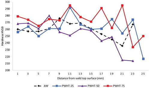
Figure 6. Micrographs of as-welded and PWHTed samples at position 2 (see ).
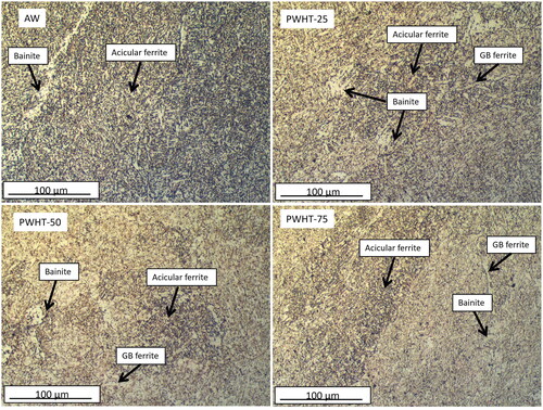
shows microstructure at position 1 (shown in ) which is the cap deposit unaffected by subsequent beads. From , AW consists mainly of acicular ferrite with some bainite in the microstructure. PWHT-75 presents almost similar microstructure plus addition of some grain boundary ferrite. PWHT-50 and PWHT-25 have much more bainite regions compared to AW and PWHT-75.
Figure 7. Macrograph of the weld showing P1 and P2 for microstructural analysis and dashed line, L for hardness measurements.
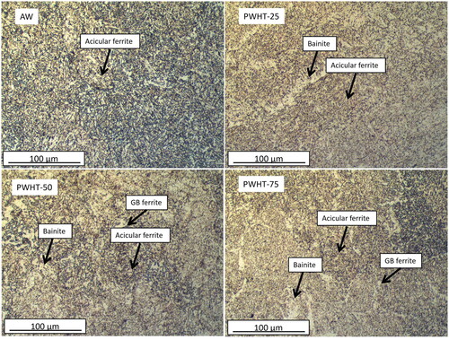
On the other hand, position 2 shows the region that had been re-heated and re-melted. The multirun deposits usually have complex microstructures. By the deposition of other layers, some areas can be reheated to austenitic temperature and cooled later to different microstructure and some areas can be only tempered. These areas are called reheated or secondary microstructure [Citation6,Citation17]. The different thermal regime may result in different microstructures and thus in noticeable changes in mechanical properties. Charpy samples were extracted from this position.
From , it is obvious that AW has the highest amount of acicular ferrite than PWHTed samples. Compared to the microstructure in position 1 (), more grain boundary ferrite can be seen in PWHT-75. PWHT-50 and PWHT-25 show big bainite regions besides the acicular ferrite.
Different strength and toughness in different samples can be related to the acicular ferrite and bainite content of the microstructure in the weld samples. The higher the bainite content, the harder the material and the lower the toughness. Acicular ferrite is believed to be the desired microstructure resulting in the best toughness in the welds. This is best seen in the case of AW where the highest toughness was achieved. PWHT-75 showed the best toughness among PWHTed samples due to its high amount of acicular ferrite. This finding aligns with research by Tomerlin et al. [Citation18], who determined that PWHT at 550 °C yielded the most favourable balance of mechanical properties and residual stress for S690QL1 high-strength steel welded joints. Their study explored PWHT at 400 °C, 530 °C, 550 °C and 600 °C, with a holding time of 4 h, identifying 550 °C as the optimal temperature for achieving up to 93% reduction in residual stress without significantly impacting the mechanical integrity of the welds. However, Tomerlin et al. did not provide a detailed microstructural analysis to further elucidate these effects.
Chemical and XRF analysis
presents chemical analysis of as welded and PWHTed samples. No significant difference in chemical analysis can be seen. PWHT-25, however, shows a bit lower Mn and Ni compared to other samples. No clear explanation may be found for this change. It can be related to the fact that a slight change in the analysis point will result in a slight change in the amount of alloying element. Based on the inclusion analysis of the polished samples using XRF, no inclusion was found in the welds.
Table 4. Chemical composition of as welded and PWHT samples (% by weight).
Conclusions
In this paper, the effect of different PWHT temperatures of 525 °C, 550 °C and 575 °C in a holding time of 2 h on the microstructure and mechanical properties of weld metal made using a HSS metal cored wire was investigated. The following conclusion can be drawn from this study.
Post-weld heat treatment increased strength slightly and decreased toughness more severely for all post-weld heat treated samples.
Post-weld heat treatment at 575 °C at two hours resulted in the best combination of strength and toughness in the weld.
Sample heated at 575 °C with higher toughness showed higher acicular ferrite and less bainite compared to other welds.
Hardness in as welded and after PWHT does not differ significantly, especially on the weld surface where all values fall to 260–280 HV approximately.
Acknowledgements
ITW Welding AB is greatly acknowledged for providing the wires.
Disclosure statement
No potential conflict of interest was reported by the author(s).
Additional information
Funding
References
- Larsson JK, Lundgren J, Asbjörnsson E, et al. Extensive introduction of ultra high strength steels sets new standards for welding in the body shop. Weld World. 2009;53(5–6):4–14. doi: 10.1007/BF03266709
- Svensson LE, Karlsson L, Söder R. Welding enabling light weight design of heavy vehicle chassis. Sci Technol Weld Join. 2015;20(6):473–482. doi: 10.1179/1362171814Y.0000000269
- Harati E, Svensson LE, Karlsson L. Comparison of effect of shot-peening with HFMI treatment or use of LTT consumables on fatigue strength of 1300 MPa yield strength steel weldments. Weld World. 2020;64(7):1237–1244. doi: 10.1007/s40194-020-00917-z
- Kah P, Pirinen M, Suoranta R, et al. Welding of ultra high strength steels. Adv Mater Res. 2013;849:357–365. doi: 10.4028/www.scientific.net/AMR.849.357
- Amraei M, Ahola A, Afkhami S, et al. Effects of heat input on the mechanical properties of butt-welded high and ultra-high strength steels. Eng Struct. 2019;198:109460. doi: 10.1016/j.engstruct.2019.109460
- Bhadeshia HKDH, MacKay DJC, Svensson LE. Impact toughness of C–Mn steel arc welds – Bayesian neural network analysis. Mater Sci Technol. 1995;11(10):1046–1051. doi: 10.1179/mst.1995.11.10.1046
- Lobanov LM, Poznyakov VD, Makhnenko OV. Formation of cold cracks in welded joints from high-strength steels with 350–850 MPa yield strength. Paton Weld J. 2016;7:7–12.
- Gliner RE. Welding of advanced high-strength sheet steels. Weld Int. 2011;25(5):389–396. doi: 10.1080/09507116.2011.554234
- Harati E, Karlsson L, Svensson LE, et al. The relative effects of residual stresses and weld toe geometry on fatigue life of weldments. Int J Fatigue. 2015;77:160–165. doi: 10.1016/j.ijfatigue.2015.03.023
- Alipooramirabad H, Paradowska A, Nafisi S, et al. Post-weld heat treatment of API 5L X70 high strength low alloy steel welds. Materials. 2020;13(24):5801. doi: 10.3390/ma13245801
- Zhao MS, Chiew SP, Lee CK. Post weld heat treatment for high strength steel welded connections. J Constr Steel Res. 2016;122:167–177. doi: 10.1016/j.jcsr.2016.03.015
- American Society of Mechanical Engineers. BPVC section VIII - rules for construction of pressure vessels division 1. New York: ASME; 2023. Available from: https://www.asme.org/codes-standards/find-codes-standards/bpvc-viii-1-bpvc-section-viii-rules-construction-pressure-vessels-division-1
- Swedish Institute for Standards. Unfired pressure vessels – part 4: fabrication (SS-EN 13445-4:2021/A1:2023). SIS; 2023. Available from: https://www.sis.se
- Jorge JCF, Monteiro JLD, Gomes AJdC, et al. Influence of welding procedure and PWHT on HSLA steel weld metals. J Mater Res Technol. 2019;8(1):561–571. doi: 10.1016/j.jmrt.2018.05.007
- Kalyankar VD, Chudasama G. Effect of post weld heat treatment on mechanical properties of pressure vessel steels. Mater Today Proc. 2018;5(11):24675–24684. doi: 10.1016/j.matpr.2018.10.265
- Jorge JCF, Faragasso SM, Guimarães de Souza LF, et al. Effect of post-welding heat treatment on the mechanical and microstructural properties of extra high-strength steel weld metals, for application on mooring equipment. Weld Int. 2015;29(7):521–529. doi: 10.1080/09507116.2014.932984
- Jorge J, Souza L, Couto JS, et al. Influence of chemical composition on the mechanical properties of high strength steel weld metals for application in mooring components. Int J Eng Techn Res. 2016;4:71–76.
- Tomerlin D, Marić D, Kozak D, et al. Post-weld heat treatment of S690QL1 steel welded joints: influence on microstructure, mechanical properties and residual stress. Metals. 2023;13(5):999. doi: 10.3390/met13050999