Abstract
Background. Magnetic Resonance Imaging (MRI) is often used in modern day radiotherapy (RT) due to superior soft tissue contrast. However, treatment planning based solely on MRI is restricted due to e.g. the limitations of conducting online patient setup verification using MRI as reference. In this study 3D/3D MRI-Cone Beam CT (CBCT) automatching for online patient setup verification was investigated. Material and methods. Initially, a multi-modality phantom was constructed and used for a quantitative comparison of CT-CBCT and MRI-CBCT automatching. Following the phantom experiment three patients undergoing postoperative radiotherapy for malignant brain tumors received a weekly CBCT. In total 18 scans was matched with both CT and MRI as reference. The CBCT scans were acquired using a Clinac iX 2300 linear accelerator (Varian Medical Systems) with an On-Board Imager (OBI). Results. For the phantom experiment CT-CBCT and MRI-CBCT automatching resulted in similar results. A significant difference was observed only in the longitudinal direction where MRI-CBCT resulted in the best match (mean and standard deviations of 1.85±2.68 mm for CT and −0.05±2.55 mm for MRI). For the clinical experiment the absolute difference in couch shift coordinates acquired from MRI-CBCT and CT-CBCT automatching, were ≤2 mm in the vertical direction and ≤3 mm in the longitudinal and lateral directions. For yaw rotation differences up to 3.3 degrees were observed. Mean values and standard deviations were 0.8±0.6 mm, 1.5±1.2 mm and 1.2±1.2 mm for the vertical, longitudinal and lateral directions, respectively and 1.95±1.12 degrees for the rotation (n=17). Conclusion. It is feasible to use MRI as reference when conducting 3D/3D CBCT automatching for online patient setup verification. For both the phantom and clinical experiment MRI-CBCT performed similar to CT-CBCT automatching and significantly better in the longitudinal direction for the phantom experiment.
Image-guided radiotherapy (IGRT) is a big part of radiotherapy today [Citation1–3]. Modern day radiotherapy planning (RTP) is done on the basis of CT in some cases supported by Magnetic Resonance Imaging (MRI). It is well known that MRI has superior soft tissue contrast compared to that of CT and several studies have established the benefits from utilizing MR images for delineation of soft tissue cancers [Citation4–10]. For some soft tissue cancers MRI-based only RT could be sufficient but is currently limited by a number of factors: 1) Geometric distortion of the MR images can affect the entire RTP process and the succeeding setup verification, 2) Dose calculation algorithms used in RTP uses the electron density acquired from a CT scan to asses tissue dose, and 3) online patient setup verification is done by using either Digital Reconstructed Radiographs (DRR's) from the CT scan, or the CT scan itself as reference. The geometric distortion is no different in MRI-based RTP than for MRI/CT based RTP and should be addressed by every department individually. In our clinic the effects of geometric distortion is well known and previously investigated by Kristensen et al. in [Citation11], where it was seen to be of no significance when scanning dimensions were <12 cm. The automatic gradient dose correction is a standard tool in our clinic and of course geometric distortions are continuous evaluated and should be quantified once again if MRI-based planning is extended to other cancers. Several authors has investigated the possibilities for dose calculation on MRI [Citation11,Citation12]. Kristensen et al. investigated the issue for brain tumors and concluded that acceptable dose calculations could be achieved when assigning a unit density water medium to the tissue and with some improvements in the low dose regions when assigning a bulk density medium with bone segmented. This leaves the issue of patient setup verification the last obstacle for an evaluation of the possibilities for performing radiotherapy based solely on MRI, hence the purpose of this study is to evaluate the use of MRI as reference for online patient setup verification during the course of radiotherapy. This topic has been investigated by several other authors [Citation13–15], but with focus on 2D/2D matching. In this study focus was on 3D/3D MRI-Cone Beam CT (CBCT) automatching with four degrees of freedom.
Material and methods
This study consisted of two main experiments. First a phantom experiment was conducted to test whether MRI-CBCT automatching was feasible and to statistically quantify its performance compared to the 3D/3D CT-CBCT matching used today. Following the phantom experiment a clinical study was completed in order to clinically verify the use of MRI-CBCT automatching. Prior to both main experiments a series of preliminary experiments were conducted to determine optimal matching settings, manual match uncertainties, phantom positioning accuracy and inter- and intra-accelerator variation.
Scanning systems
All CT scans were conducted on a Philips Brilliance CT - Big Bore Oncology (Philips Medical Systems). MR imaging was done utilizing a Philips Achieva 1.5 A-series (Philips Medical Systems). All CBCT scans were conducted with the On-Board Imager (OBI) on a Clinac iX 2300 linear accelerator (Varian Medical Systems) [Citation16,Citation17] using version 1.4 of the OBI software.
Phantom design
A multi-modality phantom was constructed consisting of four isolated sections constructed of acrylic glass designed with a cylindrical shape and an inner diameter of 120 mm. Four equally spaced vertical alignment mills on the outer surface of the cylinders along with a milled alignment cross in the lid, allowed for a high positioning accuracy and easy setup against the laser positioning systems used in the clinic.
As main ingredient, polyurethane (Biresin U1404, German Sika) was used. Polyurethane has physical properties making it ideal for phantom design: When hardened, shrinkage is minute (<0.04%) and the material can be stored at room temperature. Additionally materials were used including natural sponge, fish oil capsules, plaster casts and pieces of pre-hardened polyurethane containing different solutions of either Barium Sulfate (BaSO4) or Manganese(II)chloride tetrahydrate (MnCl2*4H20), two well known CT and MRI contrast agents. Besides adding fat equivalent areas to the phantom the fish oil capsules with their distinctive shape made a great tool for visually verifying CT-CBCT as well as MRI-CBCT matches. To evaluate the phantom materials a preliminary experiment was undertaken and two phantom sections were chosen for further use in this study. shows the final phantom on the treatment couch aligned with the laser positioning system prior to a CBCT scan. shows a CT scan of two of the phantom sections. The fish-oil capsules can be easily identified in the center of the upper section.
Figure 1. The two sections of the multi–modality phantom used, here aligned with the setup positioning lasers on the treatment couch prior to CBCT scan.
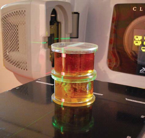
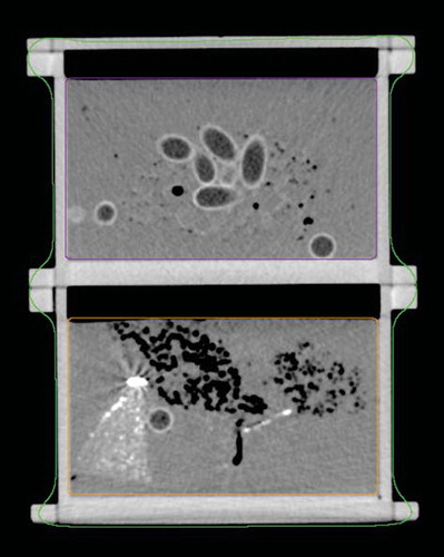
Figure 2. A CT image of the two phantom sections used also showing the delineation into a Body structure, the upper section (Box 1) and lower section (Box 2). In the upper section the fish oil capsules are clearly visible along with small air encapsulations. The bright area in the left side of the lower section is a part of pre-hardened polyurethane containing a solution of BaSO4.
Pre-treatment scanning procedure and image handling
Initially both CT and MRI reference scans of the phantom was recorded. The alignment mills on the phantom surface were used to correctly position the phantom with the scanner isocenter. The CT scan was conducted with a slice thickness of 2.0 mm, a pixel spacing of 0.53;0.53 mm and an image dimension of 512 × 512 pixel. For the MRI scan a T1 weighted first field echo series (T1W-3D-FFE) was used and slice thickness, pixel spacing and image dimension was 1.16 mm, 0.58;0.58 mm and 352 × 352 pixel, respectively. Both reference scans were imported via DICOM into the treatment planning system (TPS), Eclipse™, v. 8.5 (Varian Medical Systems). Eclipse supports multi-modality (CT, MRI, PET) image registration using a mutual information algorithm. However, the OBI software used for the online patient setup verification currently supports only the CT modality, preventing the possibility to utilize MR images as reference for an online 3D-3D match. To overcome this, the MRI reference scan was camouflaged as a CT scan by modifying several attributes in the DICOM header. This task involved generating new unique identifiers (UID's) for the SeriesInstaceUID, the StudyInstanceUID and the SOPInsstanceUID attributes using the dicomuid command in MATLAB. Thus, the MRI scan appeared throughout the system as a CT scan.
Subsequently both phantom scans were delineated. The auto delineation function formed a body contour, delineating the entire phantom while two manual delineations was added, one around each phantom section (). During CBCT matching the OBI software allows the user to limit the area of the reference scan used by the matching algorithm. This allowed for a larger data material as matching could be repeated for each individual section of the phantom. To ensure that both reference scans had the same isocenter an image registration was performed with the TPS's automatching function. Following the automatch the match was visually verified.
In order to conduct online matching on the OBI a treatment plan has to be transferred from the TPS. In this case two treatment plans were created, one based on each of the two reference scans. The treatment plans, including one CBCT setup field, bared no other difference beside the modality of the reference scan.
OBI matching parameters
The OBI software allows the user to change several matching parameters prior to the automatching procedure. A preliminary experiment was conducted to investigate these parameters and their optimal settings for conducting MRI-CBCT automatching. shows the parameters available for customization with default and selected settings highlighted.
Table I. Automatching parameters available for customization on the OBI. Selected settings are highlighted with italic.
Preliminary experiments
To evaluate the performance of the online automatch a manual match was used as the true image translation. Therefore, the precision of manual matching was evaluated by a series of ten manual matches conducted on a single CBCT scan of the phantom. Further to evaluate setup errors the phantom was positioned, scanned and repositioned six consecutive times followed by matching with CT as reference.
Intra- and inter-accelerator variation was also evaluated. The phantom was scanned six consecutive times at one accelerator without changing phantom position, couch position or scan settings. All six CBCT scans were then automatched with CT as reference and the results compared. Inter-accelerator variation was evaluated by repeating the experiment at two other accelerators.
Phantom experiment
The purpose of the phantom experiment was to investigate whether it is possible to conduct online 3D/3D MRI-CBCT automatching and to evaluate its performance compared to the currently used 3D/3D CT-CBCT automatching. The experiment was constructed to simulate random inter-fraction setup errors. The phantom was positioned at the treatment couch and aligned at the treatment isocenter using the laser positioning system. To ensure that the phantom was positioned precisely setup was followed by a CBCT scan and a manual match. If the manual match showed a setup error a couch shift was executed to adjust for this and the process repeated until the phantom was positioned accurately at the isocenter. To simulate a random setup error, the treatment couch was now moved in a series of predefined positions in the vertical and longitudinal directions, each position simulating a new random setup error. Following each of these positions the phantom was rescanned and an automatch performed. Ideally, the automatch should result in a couch shift corresponding to the simulated setup error. The experiment consisted of 30 CBCT scans with simulated setup errors of +4 mm, +1 mm, −1 mm and −4 mm in the vertical and longitudinal directions. To gain a larger data pool for analysis the automatching was completed within the two structures of the reference scans, i.e. Box 1 and 2. As the automatch was repeated with both CT and MRI as reference, a total of 120 match results were analyzed.
As the introduced positioning error was known so was the true shift coordinates. The error between the true shift coordinates and the shift coordinates determined by the automatching algorithm was used for evaluation. Data analysis consisted of mean and standard deviations for both CT-CBCT and MRI-CBCT automatching in the vertical, lateral and longitudinal directions. A one-sided t-test was conducted to test whether a significant difference existed between the mean values of the error for CT-CBCT and MRI-CBCT automatching. The t-test was conducted for all three directions.
Clinical experiment
Following the phantom experiments a clinical experiment was completed. Three patients with malignant brain tumors receiving postoperative radiotherapy consisting of 2 Gy fractions for a total of 60 Gy received a weekly CBCT, i.e. a total of six CBCT scans each. As part of the current standards all three patients were CT and MRI scanned prior to RTP. Normal clinical procedures were followed during patient setup and couch coordinates noted after which the CBCT scan was completed. The CBCT scan was matched online against the CT reference scan using the automatching algorithm, the match visually verified, and the treatment session completed. The experiment was completed at a later stage without the involvement of the patients. The couch was positioned in coordinates noted prior to the treatment and a copy of the treatment plan now based on a MRI scan was loaded. The MRI had been modified to appear as a CT scan in the same manner as described for the phantom experiments. The CBCT scan was then reconstructed on the OBI software and the matching procedure completed with the camouflaged MRI as reference. As the true match for the clinical case was not known the results for this part of the study were evaluated by comparing the absolute difference between couch shift coordinates from CT-CBCT and MRI-CBCT.
Results
Preliminary experiments
Manual matching uncertainties is estimated to be neglectable with standard deviations of 0.48 mm, 0.00 mm, and 0.53 mm for the vertical, longitudinal and lateral directions, respectively and 0.39° for the rotation (yaw). The evaluation of setup errors yielded 24 shift coordinates including the rotation. In only one of these a shift was necessary to adjust for a 1 mm error during the setup process. On this basis setup errors are estimated to be neglectable in this study.
Hardly any intra-accelerator variation was observed. In the vertical, longitudinal and lateral directions differences were within ±1 mm with standard deviations <0.41 mm. Although small, an inter-accelerator variation was present and observable in all directions. To eliminate the uncertainties of inter-accelerator variation all following experiments were conducted at the same accelerator.
Phantom experiment
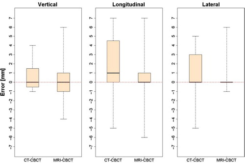
shows three box plots of the shift errors in the vertical, longitudinal and lateral directions for CT-CBCT and MRI-CBCT automatching. For CT-CBCT the errors span from −1 to 4 mm, −5 to 7 mm and −5 to 5 mm in the three directions. For MRI-CBCT the range of the errors is about the same size spanning from −4 to 6 mm, −6 to 7 mm and −1 to 6 mm in the three directions. The whiskers extend to the largest errors and no data points are considered as outliers. All six plots show a similar median around zero with CT-CBCT in the longitudinal direction being the only with a median shifted to a higher value. Visually the results are comparable. The t-test shows no significant difference between CT-CBCT and MRI-CBCT in the vertical and lateral directions. For the longitudinal direction a significant difference exists (p-value = 0.001897) and in this case MRI-CBCT resulted in the best automatch as seen by the mean and standard deviations (). However, when evaluating these results it should be noted that no setup errors were introduced in the lateral direction.
Table II. Mean and standard deviations for the vertical, longitudinal and lateral errors for CT-CBCT and MRI-CBCT automatching.
Figure 3. Box plots showing the error distribution in the vertical, longitudinal and lateral directions for CT-CBCT and MRI-CBCT automatching, respectively. The plots contain all data points for both structures (Box 1 and Box 2). The whiskers extend from the minimum and maximum value. The box limits represents the 25th and 75th percentiles and the black lines the sample median.
Clinical experiment
As mentioned the clinical experiment was evaluated by comparing the absolute difference between couch shifts coordinates from CT-CBCT and MRI-CBCT automatching. The absolute differences between these were ≤2 mm in the vertical direction and ≤3 mm in the longitudinal and lateral directions (). For couch rotation, differences up to 3.3 degrees were observed. Mean values and standard deviations were 0.8 ± 0.6 mm, 1.5 ± 1.2 mm and 1.2 ± 1.2 mm for the vertical, longitudinal and lateral directions, respectively and 1.95 ± 1.12 degrees for the yaw rotation. For one of the 18 cases the automatching algorithm was only capable of finding a match using MRI as reference why the above analysis is based on only 17 data points (n=17).
Figure 4. Absolute difference in couch shift coordinates [mm] between CT-CBCT and MRI-CBCT automatching for the vertical, longitudinal and lateral directions. Data from all three patients are plotted and separated by the two vertical lines.
![Figure 4. Absolute difference in couch shift coordinates [mm] between CT-CBCT and MRI-CBCT automatching for the vertical, longitudinal and lateral directions. Data from all three patients are plotted and separated by the two vertical lines.](/cms/asset/608e12c6-231e-41c3-995e-ff726427d90b/ionc_a_498442_f0004_b.jpg)
Discussion and conclusions
It is feasible to conduct 3D/3D MRI-CBCT automatching for online patient setup verification as demonstrated in the phantom study. Knowing the true setup error made it possible to evaluate the results with a higher accuracy than for the clinical study. A significant difference between CT-CBCT and MRI-CBCT automatching existed only in longitudinal direction and in this case MRI-CBCT yielded the best automatch. Although there is no mathematically hindrance for MRI-CBCT having a better local optimum than CT-CBCT, this is more likely to be a result from the finer slice thickness of 1.16 mm the MRI scan compared to the 2 mm used for CT.
The clinical study confirmed the results from the phantom experiment; i.e. both CT-CBCT and MRI-CBCT automatching are able to identify the presence of setup errors in RT of brain tumors. Data analysis for the clinical case was complex as random and systematic errors remain unknown. However, the comparison of CT-CBCT and MRI-CBCT in terms of the absolute difference between couch shift coordinates provides a good indication of the MRI-CBCT performance. No differences >3 mm for the longitudinal and lateral directions and only differences up to 2 mm for vertical direction were observed (). As the resolution of the OBI software is 1 mm, these differences are considered small. Furthermore, the mean and standard deviations yields no indication that MRI-CBCT automatching performs significantly worse than CT-CBCT. In some cases a visual inspection of the match results pointed at MRI-CBCT as the best match, however as this cannot be mathematically quantified a further analysis was not conducted.
When considering introducing MRI-based only RT in the clinic the gains should be weighed against the cost. Compared to the typically RT used today, based on both a reference CT and a reference MRI, MRI-based only RT holds several advantages namely: A more flexible clinic by simplifying working procedures, reduced workload on CT scanners and possibly reduced systematic errors by omitting the initial MRI-CT match prior to RTP. This study shows that it is feasible to conduct 3D/3D MRI-CBCT automatching for online patient setup verification for RT of brain tumors and thereby allowing for MRI-based only RT on brain tumors. In addition it is the author's belief that MRI-based only RT can be successfully implemented in palliative treatment of spinal cord compressions where patients would benefit from a faster treatment time and lesser painful moves by avoiding the initial CT scan. Prostate cancer patients could also be considered as delineation of these patients is already based on MRI. Of course this would require a reassessment of the effects of the geometric distortion and issues concerning dose calculation. We are currently investigating these issues for both Intensity Modulated Radiotherapy (IMRT) and Volumetric Modulated Arc Therapy (VMAT) of prostate cancer.
Acknowledgements
The department has in 2010 received funding from the Research Collaborations Program (Varian Medical Systems) for further investigations within the field of MRI-based radiotherapy planning and the subject of this study.
Declaration of interest: The authors report no conflicts of interest. The authors alone are responsible for the content and writing of the paper.
References
- Greco C, Clifton Ling C. Broadening the scope of image-guided radiotherapy (IGRT). Acta Oncol 2008;47:1193–200.
- Grau C, Muren LP, Høyer M, Lindegaard J, Overgaard J. Image-guided adaptive radiotherapy – integration of biology and technology to improve clinical outcome. Acta Oncol 2008;47:1182–5.
- Baumann M, Holscher T, Zips D. The future of IGRT – Cost Benefit Analysis. Acta Oncol 2008;47:1188–92.
- Khoo VS, Adams EJ, Saran F, Bedford JL, Perks JR, Warrington AP, . A comparison of clinical target volumes determined by CT and MRI for the radiotherapy planning of base of skull meningiomas. Int J Radiat Oncol Biol Phys 2000;46:1309–17.
- Rasch C, Barillot I, Remeijer P, Touw A, van Herk M, Lebesque JV. Definition of the prostate in CT and MRI: A multi-observer study. Int J Radiat Oncol Biol Phys 1999; 43:57–66.
- Aoyama H, Shirato H, Nishioka T, Hashimoto S, Tsuchiya K, Kagei K, . Magnetic resonance imaging system for three-dimensional conformal radiotherapy and its impact on gross tumor volume delineation of central nervous system tumors. Int J Radiat Oncol Biol Phys 2001;50:821–7.
- Krempien RC, Schubert K, Zierhut D, Steckner MC, Treiber M, Harms W, . Open low-field magnetic resonance imaging in radiation therapy treatment planning. Int J Radiat Oncol Biol Phys 2002;53:1350–60.
- Jansen EPM, Dewit LGH, van Herk M, Bartelink H. Target volumes in radiotherapy for high-grade malignant glioma of the brain. Radiother Oncol 2000;56:151–6.
- Khoo VS, Dearnaley DP, Finnigan DJ, Padhani A, Tanner SF, Leach MO. Magnetic resonance imaging (MRI): Considerations and applications in radiotherapy treatment planning. Radiother Oncol 1997;42:1–15.
- Weltens C, Menten J, Feron M, Bellon E, Demaerel P, Maes F, . Interobserver variations in gross tumor volume delineation of brain tumors on computed tomography and impact of magnetic resonance imaging. Radiother Oncol 2001;60:49–59.
- Kristensen BH, Laursen FJ, Løgager V, Geertsen PF, Krarup-Hansen A. Dosimetric and geometric evaluation of an open low-field magnetic resonance simulator for radiotherapy treatment planning of brain tumours. Radiother Oncol 2008;87:100–9.
- Eilertsen K, Vestad LNTA, Geier O, Skretting A. A simulation of MRI based dose calculations on the basis of radiotherapy planning CT images. Acta Oncol 2008;47: 1294–302.
- Ramsey CR, Oliver AL. Magnetic resonance imaging based digitally reconstructed radiographs, virtual simulation, and three-dimensional treatment planning for brain neoplasms. Med Phys 1998;25:1928.
- Ramsey CR, Arwood D, Scaperoth D, Oliver AL. Clinical application of digitally-reconstructed radiographs generated from magnetic resonance imaging for intracranial lesions. Int J Radiat Oncol Biol Phys 1999;45:797–802.
- Yin FF, Gao Q, Xie H, Nelson DF, Yu Y, Kwok WE, . MR image-guided portal verification for brain treatment field. Int J Radiat Oncol Biol Phys 1998;40:703–11.
- Sjostrom D, Bjelkengren U, Ottosson W, Behrens CF. A beam-matching concept for medical linear accelerators. Acta Oncol 2009;48:192–200.
- Ottosson RO, Engstrom P, Ceberg C, Behrens CF, Sjostrom D. The feasibility of using Pareto fronts for comparison of treatment planning systems and delivery techniques. Acta Oncol 2009;48:233–7.