Abstract
Purpose. The aim of this study is to evaluate the patient setup accuracy by investigating the impact of different types of CBCT matches, performed with 3 (translations only) or 6 (including rotations) degrees-of-freedom (DOF). The purpose is also to calculate and compare CTV to PTV margins based on the various CBCT matches, setups using 2D kV planar imaging or setups using skin markers only (non-IGRT). Material and methods. Setup images from 16 NSCLC patients with weekly CBCT and daily 2D kV planar imaging were analyzed retrospectively. The CBCT matches were based on the columna vertebralis (CV), the whole thorax (WT) and the soft tissue (ST) delineated GTV, where the ST match was chosen as reference. Thus the translational and rotational shifts in three dimensions were assessed. Finally, setup margins were calculated using van Herk's margin recipe. Results. For 80% of the investigated 3 DOF/2D kV CV setups, the translational shifts were within [−3, 2] mm for all three directions. Corresponding values for the 6 DOF/non-IGRT CV and the 6 DOF/non-IGRT ST matches were [−5, 8] mm. Furthermore, 80% of all setups were within ± 2° for pitch-, roll- and yaw-rotations, and none exceeded 5°. The calculated margins for non-IGRT, about 10 mm, were reduced to approximately 4 mm, regardless of using IGRT setup by CBCT or 2D kV imaging on CV. However, if using WT CBCT setup, the margin in LNG direction was slightly larger, approximately 6 mm. Conclusion. IGRT for NSCLC is an essential tool for margin reduction, since patient setups based on IGRT leads to approximately half the margin sizes compared to non-IGRT setups. Both CBCT and 2D kV planar imaging yields approximately the same margins for CV/ST matches. The magnitudes of the patient rotations were <5°.
When utilizing radiotherapy for treating tumors, a large safety margin is often applied around the clinical target volume (CTV) and the organs at risk (OARs) to ensure no under- and overtreatment caused by geometrical uncertainties. The extent of the applied margins can affect the clinical outcome of the patients. To spare healthy adjacent tissues (i.e. limiting the normal tissue complication probability (NTCP) for the patient) the dose to the tumor is often compromised, which affects the tumor control probability (TCP) negatively [Citation1]. It is therefore important to quantify the geometrical uncertainties, and thereby assess the applied margins more correctly to preserve a high TCP and a low NTCP. Van Herk et al. [Citation2,Citation3] derived a formula to calculate a planning target volume (PTV) margin applied to the CTV, which ensures that the minimum dose to the CTV is 95% of the prescribed dose for 90% of the patients. The margin calculation is based on systematic and random errors assessed by the positional errors. Image guided radiotherapy (IGRT) is nowadays commonly used in many radiotherapy centers to verify patient positioning prior to treatment [Citation4–6]. IGRT provides an essential tool to investigate the geometrical uncertainties, to quantify them, and in turn correct for them [Citation7]. The reduction of the geometrical uncertainties enables tightening of the applied margins around the CTV [Citation1,Citation8], which enables dose escalation without compromising adjacent OARs and normal tissue.
There are several image guidance modalities on the market with different advantages and disadvantages [Citation1]. Orthogonal 2D kV planar imaging for positional verification of the patient is well suited for bony match, but soft tissue tumors are often hard to visualize. On the other hand, utilization of a 3D cone-beam CT (CBCT) scan for positional verification enables automatic matching on different types of structures (including soft tissue), and gives a quantitative measure of translational as well as rotational shifts in all directions. Estimations of the consequences of incorrect positioning of the patients are thereby possible. It has been reported by Borst et al. [Citation9] and Purdie et al. [Citation10] that positional verification by CBCT imaging is superior to orthogonal 2D MV portal imaging, especially for non-small-cell lung carcinoma (NSCLC) patients. However, CBCT imaging is a time consuming process, compared to 2D MV portal imaging. Since 2D kV planar images have better contrast and more similarities with the reference DRRs, compared to 2D MV portal images, it is clinical relevant to compare the setup accuracy when using 2D kV planar imaging or CBCT imaging for patient setup.
The aim of this study is to evaluate the patient setup accuracy for NSCLC patients by investigating the impact of three different types of CBCT matches based on the whole thorax (WT) anatomy, the bony structure of columna vertebralis (CV), and the soft tissue (ST) of the delineated gross tumor volume (GTV). The objective is also to investigate the magnitude of the rotational shifts assessed from the CBCT matches and their impact on the translational shifts. Furthermore, utilizing the ST match as reference, the purpose is to calculate and compare the population-based CTV to PTV margins based on the translational shifts assessed from the various CBCT matches, setups using 2D kV planar imaging on columna vertebralis, or setups using skin markers only (non-IGRT).
Material and methods
Patient data
This study includes 16 NSCLC patients treated between mid October 2009 and May 2010 at Herlev Hospital. The patients were treated on Varian Clinac iX 2300 linear accelerators [Citation11] (Varian Medical Systems, Palo Alto, CA) equipped with On-Board Imagers (OBI) capable of performing CBCT, using version 1.4 of the OBI software. A dose of 60–66Gy (2Gy/fraction) was prescribed to the PTV.
Reference image set
Each patient was immobilized by an individualized VacFix (PAR Scientific A/S, Odense, Denmark). The patients were scanned with a 16 slice Philips Brilliance CT Big Bore, version 2.3.0 (Philips Medical Systems, Cleveland, OH) integrated with a Varian real-time position management (RPM) system, version 1.7 (Varian Medical Systems), utilized for monitoring the respiratory motion of the patients during CT scanning [Citation12]. The obtained respiratory motion curves, representing the movement of the umbilical region during the scan, were utilized for 4-dimensional CT (4DCT) image reconstructions. The respiratory correlated 4DCT scanning was performed using a free-breathing retrospective helical thorax protocol. From the 4DCT scan, ten phase-sorted breathing phases were derived, along with the UnTagged-reconstruction. The UnTagged image set is a time weighted reconstruction with a true HU representation, and is therefore utilized for treatment planning and dose calculations [Citation13], as well as the reference image set for the patient positional verification at the accelerators. The ten phases were used to reconstruct the maximum intensity projection (MIP) image set. The patients were additional scanned with a 16 slice GEMINI TF Big Bore PET/CT, version 2.3 (Philips medical Systems). The image sets were imported and co-registered in the Eclipse treatment planning system, version 8.8 (Varian Medical Systems).
A radiation oncologist, specialized in lung cancer treatments, and a radiologist delineated the GTV using information from the co-registered MIP and PET/CT scan. In addition, an evaluation of the ten breathing phases was performed to correct and verify the GTV delineation in all breathing phases. The final GTV was generated as a union of the GTVs in all the ten breathing phases [Citation14]. A margin of 0.5 cm was used for the CTV, excluding bone structures and adjacent organs (if there were no suspicion of soft tissue invasion), and a standard isotropic margin of 0.5 cm, around the CTV, was used for the PTV. The delineations were eventually transferred to the UnTagged image set for treatment planning and dose calculations. Characteristics of the UnTagged image set can be seen in .
Table I. Characteristics of the UnTagged and the CBCT image sets.
On-board image set and offline match procedure
Initial setup was performed by aligning the patient's skin markers (tattoos) to the room lasers. A CBCT scan was thereafter acquired, where the radiation therapist personnel matched on the WT for online positional correction. Orthogonal 2D kV planar images were subsequently acquired for positional verification of the performed CBCT correction. Weekly CBCT scans (according to the patient setup procedure described above) and daily orthogonal 2D kV images were acquired for positional verification prior to treatment for the remaining treatment sessions. The Varian low-dose thorax CBCT scanning protocol was utilized with 655 projections acquired over an arc of 360° using a half fan scan, with an acquisition time of about 1.5 min [Citation15,Citation16] (). The orthogonal 2D kV planar images were acquired using the gantry angles 0° and 270°.
To evaluate the patient setup accuracy, matching of the daily 2D kV planar images and the weekly CBCT images were accomplished retrospectively in the commercial registration software Offline Review, version 8.8 (Varian Medical System), where the UnTagged image set was utilized as reference. The matches were carried out solely by one observer (WO), to minimize the inter observer influence. The 2D kV planar images were manually matched on the bony structure of the columna vertebralis. The CBCT matches were performed automatically, where visual verifications of the matches were carried out subsequently by using a mix of complimentary colors on the registered image sets. Modification of the automatic match results were done if indicated by the visual verification. The automatic match method utilized for the CBCT images is intensity-based, following the mutual information concept [Citation16–18]. The matching algorithms utilize rigid transformation, consisting of a translational part and a rotational part. A positional verification system, where the translational as well as the rotational shifts in three directions are assessed, works in 6 degrees-of-freedom (DOF). Corresponding system, where the rotational shifts are excluded, works only in 3 DOF. All types of CBCT matches were performed using 3 and 6 DOF for comparison. The magnitudes of the rotations, assessed from the 6 DOF CBCT matches, and their impact on the translational shifts were investigated. For the 2D kV planar images no rotations were included in the matches (3 DOF).
The CBCT matches were based on three types of anatomy matches; WT, CV and ST (). During comparison of these various CBCT matches, the setup parameters of the ST match were used as reference. The automatic matches were based on the “Thorax 3D” parameter set in Offline Review, where the “Thorax 3D” parameter set consisted of values predefined by Varian, to achieve the best match. The intensity range alternative was activated in Offline Review to focus the matches on the columna vertebralis and the tumor itself (i.e. the delineated GTV) when performing the CV and ST matches, respectively (). Totally 85 CBCT images and 73 2D kV planar images (excluding two patients) were acquired and analyzed for the 16 NSCLC patients. In total 510 CBCT matches and 73 2D kV planar imaging matches were evaluated. Only the 2D kV planar images, acquired at the same treatment session as the CBCT images, were included in this study.
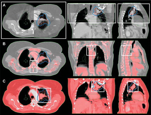
Figure 1. A user-defined 3D rectangular ROI (white box) when performing a WT (A), CV (B) and ST (C) CBCT match. (A) The cranio-caudal (CC) borders of the ROI were limited by the length of the CBCT scan. The left-right (LR), and the anterior-posterior (AP) borders were positioned just outside the thorax volume to assure whole thorax volume inclusion in the ROI. (B) The CC borders of the ROI were limited by the extent of the PTV (blue line). The LR, and the AP borders were positioned just outside the columna vertebralis when using bone window level in Offline Review. The volume within the ROI utilized for the CV match is colored red (i.e. the pixels with an intensity range of 50–3000 HU). (C) The CC borders of the ROI were limited by the extent of the PTV. The LR, and the AP borders were positioned next to the PTV. The volume within the ROI utilized for the ST match is colored red (i.e. the pixels with an intensity range of -150-150 HU) (Color version of figure is available online.)
Since the patient's tattoos were aligned to the room lasers prior to CBCT image acquisition, they were well defined in absolute image coordinates in the CBCT scan as the acquisition position. The translational shifts between the acquisition position and the 6 DOF CV as well as 6 DOF ST match positions were assessed to evaluate the patient setup accuracy when performing patient positioning without image guidance (non-IGRT).
The translational shifts between the 3 DOF CV match and the 2D kV planar imaging match on CV were assessed, to evaluate the agreement of the two types of CV matches, where the 3 DOF CV match was considered as reference. The translational shifts between the setup parameters of the 2D kV planar imaging match on CV and the 6 DOF ST match were additionally assessed to calculate the CTV to PTV margin, described below.
Error definition and margin calculations
Systematic (Σ) and random (σ) components of the setup error as well as the group systematic error (GM), according to van Herk [Citation3], were calculated for the various translational shifts. For each patient the mean of the translational shifts (MP) and corresponding standard deviation (SDP) were calculated. Accordingly for the patient population Σ was defined as the standard deviation (SD) of all MP, σ as the root mean square of all SDP, and GM as the mean of all MP. The systematic error, which originates from the treatment preparation process, will remain throughout the treatment course if not corrected for. In contrast the random errors vary among the fractions. Information about the patients’ setup displacements throughout the treatment enables assessment of the systematic and the random errors of the population. Population-based CTV to PTV margins (M) can be calculated by using the van Herk formula, [Citation2,Citation19]:
where the parameter σP = 0.64 cm describes the width of the penumbra in lung tissue modeled by a cumulative Gaussian, and β = 1.64 assures delivery of 95% of the prescribed dose to 90% of the patient population [Citation20–22]. The underlying assumption is that the resulting PTV is larger compared to the width of the penumbra [Citation19]. The displacements between the various anatomy matches relative to each other were assessed, and related margins were calculated accordingly. Since rotations could not be included in the margin formula, only the assessed translational shifts were used for the calculations.
For statistical analysis MATLAB Statistics Toolbox version 7.1 (R2009a) (The MathWorks, Natick, MA) was used. Paired t-tests for evaluating the data were performed, where differences were considered significant for p <0.05.
Results
Maximum translational shifts between the 3 DOF CV match and the 2D kV planar imaging match on CV were found to be ± 4 mm (). Based on these data the 10th/90th percentiles were found to be –2/2 mm in the LNG and LAT direction. Corresponding values for the VRT direction were –3/1 mm. GM, Σ and σ were all within ± 1 mm for the translational shifts in the VRT, LNG and LAT directions.
Figure 2. Translational shifts (VRT, LNG and LAT) between the 3 DOF CV match and the 2D kV planar imaging match on CV.
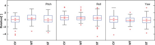
Rotations for the various 6 DOF CBCT matches performed were found to be < 5° (). The data corresponding to the 10th/90th percentiles were –2/2° in all rotational directions for all types of CBCT matches. The largest spreads in rotation were seen for the pitch rotation.
Figure 3. Rotations (Pitch, Roll and Yaw) for the 6 DOF CV, WT and ST matches. On each box, the central mark is the median, the edges of the box are the 25th and 75th percentiles, the whiskers corresponds to approximately ± 2.7 SD, outliers are plotted as red crosses individually, the notches corresponds to the confidence interval of the median. If the notches do not overlap for the various group data it can be concluded, with 95% confidence, that the true medians differ.
There are significant differences for the translational shifts when using non-IGRT () or image guidance () for patient setup. The 10th/90th percentiles of the translational shifts between 6 DOF CV/non-IGRT or 6 DOF ST/ non-IGRT were similar, except in the VRT direction (), where the values were −3/6 mm and −1/6 mm, respectively. For both types of matches, GM, Σ and σ were found to be within [−1, 2] mm, [2, 3] mm and [2, 4] mm, respectively, for all directions, with largest GM value in the VRT direction and largest Σ and σ values in the LNG direction. The 10th/90th percentiles of the translational shifts when performing CBCT IGRT between 3/6 DOF CV/ST or 3/6 DOF WT/ST matches were similar, except in the LNG direction (), where the values were, −2/2 mm and −2/4 mm, respectively. For both types of matches, GM, Σ and σ were found to be within [0, 1] mm, [1, 2] mm and [1, 2] mm, respectively, for all directions, with largest GM, Σ and σ values in the LNG direction. Σ and σ for the LNG direction of the 3/6 DOF WT/ST match were slightly larger than for the 3/6 DOF CV/ST match, resulting in a larger CTV to PTV margin ().
Figure 4. (A) Translational shifts (VRT, LNG and LAT) between the non-IGRT setup and the 6 DOF CV and ST matches. (B) Translational shifts for the 3/6 DOF CV/ST, as well as the WT/ST matches.
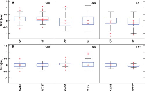
Table II. Summary of the calculated CTV to PTV margins.
CTV to PTV margins for non-IGRT patient setups were calculated to be 7–10 mm in the VRT and LNG direction (), and about 6 mm in the LAT direction. When performing 2D kV planar imaging matches on CV the calculated CTV to PTV margins were reduced to about 4 mm (). These margins were similar to the calculated margins based on CBCT matches of 3/6 or 6/6 DOF CV/ST (). Comparable margin sizes were calculated for matching on 3/6 or 6/6 DOF WT/ST in the VRT and LAT direction, while slightly larger margins (5–6 mm) in the LNG direction were found. The margin sizes were found to be similar, regardless of performing the CBCT matches in 3 or 6 DOF.
Discussion
The margins calculated in this work do not include errors from target delineation, couch adjustment, imager calibration, etc. Inclusion of these errors might reduce the difference in margin magnitude between IGRT and non-IGRT treatments. If included, the SDs of the errors should be added in quadrature [Citation3]. To receive the best patient setup verification prior to treatment it is important to use a fast imaging procedure, since the patients are likely to move between image acquisition and treatment. The 2D kV image acquisition procedure is less time consuming, compared to CBCT imaging. This study shows a good agreement between the 2D kV planar imaging match on CV and the 3 DOF CBCT CV match (). No significant differences between the margin sizes were found, which implies that CV matching by utilizing CBCT imaging instead of 2D kV planar imaging cannot reduce the size of the applied CTV to PTV margin (). However, the uncertainty of 2D kV planar imaging matches are often larger, since it is performed only in two dimensions and both the 2D kV planar images and the DRRs of thorax often have poor image quality. Since the acquisition time for a CBCT image set is approximately 1.5 min, not only soft tissue information and the tumor position, but also information about the extent of the tumor motion can be addressed [Citation23]. Thus, the CBCT image set will be well comparable to the UnTagged reference image set. The image quality of the CBCT images acquired in this study was sufficient for verification of the tumor positions for all patients. The CBCT is thereby useful to verify that correct delineation of the union GTV is made. However, the use of union GTV to encompass the respiratory motion instead of using the mid ventilation phase concept [Citation19] for the GTV delineation can result in a slightly larger PTV volume. The latter approach is considerably sufficient for stereotactic body radiotherapy (SBRT), where small primary tumors without involved lymph nodes are treated with high dose in just a few fractions. Our patients often had lymph node disease involvement. Systematic baseline shifts between tumor and involved lymph nodes can be introduced due to differential motions [Citation19]. To minimize the influence of systematic baseline shift between the primary tumor and the involved lymph nodes when performing ST match it is important to use a match ROI that involves the total PTV (i.e. including primary tumor and the involved lymph nodes). Further, it is important to be aware that performing a ST online positional correction of the patient prior to treatment might lead to overexposure of the healthy adjacent tissues. To gain maximum benefit from daily CBCT, i.e. to be able to precisely match on the tumor instead of a tumor surrogate, e.g. the columna vertebralis, and to estimate amplitude changes and baseline shifts, 4D CBCT imaging is preferable [Citation19,Citation23]. However, before a method to perform 4D CBCT is available in our clinic, we do not plan to match directly on the tumor.
The Σ and σ when performing WT/ST CBCT matching were found to be larger in the LNG direction compared to CV/ST matching by 2D planar images or CBCT imaging. This resulted in a larger CTV to PTV margin (). A possible explanation for this can be the fact that many of our patients had their tumors located close to the columna vertebralis in the middle or upper lung lobes. The larger CTV to PTV margins calculated for the WT/ST CBCT matches emphasize the possible benefits of doing ST match for NSCLC patients.
There is no easy way to correct for rotations in the clinic without a robotic couch available [Citation7]. The CBCT matching software enables matching in 6 DOF, and thereby the magnitude of the rotations can be assessed. In this study the patient rotations were small (). Positional corrections of these rotations were only made with translational shifts. The derived CTV to PTV margins were approximately the same, regardless if the CBCT matches were performed in 3 or 6 DOF (), and therefore one would not gain much with a robotic couch in respect to margin reduction. Since only small rotations were found, we conclude that our fixations of the patients serve their purpose well, allowing for accurate repositioning of the patients for each treatment session.
Conclusion
IGRT for NSCLC is an essential tool for better patient positioning and for margin reduction. Patient setups based on image guidance lead to approximately half the margin sizes in comparison to non-IGRT setups. The calculated CTV to PTV margins were approximately the same regardless if CBCT or 2D kV planar image guidance were used for patient positioning. Furthermore, the magnitudes of the patient rotations for all CBCT matches were < 5°.
Acknowledgements
The results of this study were presented as a poster at the Acta Oncologica Symposium on biology-guided adaptive radiotherapy, BIGART 2010, in Aarhus, Denmark, on May 26–28, 2010.
Declaration of interest: The authors report no conflicts of interest. The authors alone are responsible for the content and writing of the paper.
References
- van Herk M. Different styles of image-guided radiotherapy. Semin Radiat Oncol 2007;17:258–67.
- van Herk M, Remeijer P, Rasch C, Lebesque JV. The probability of correct target dosage: Dose-population histograms for deriving treatment margins in radiotherapy. Int J Radiat Oncol Biol Phys 2000;47:1121–35.
- van Herk M. Errors and margins in radiotherapy. Semin Radiat Oncol 2004;14:52–64.
- Grau C, Muren LP, Høyer M, Lindegaard J, Overgaard J. Image-guided adaptive radiotherapy – integration of biology and technology to improve clinical outcome. Acta Oncol 2008;47:1182–5.
- Greco C, Clifton Ling C. Broadening the scope of Image-Guided Radiotherapy (IGRT). Acta Oncol 2008; 47:1193–200.
- Baumann M, Hölscher T, Zips D. The future of IGRT – Cost Benefit Analysis. Acta Oncol 2008;47:1188–92.
- Guckenberger M, Meyer J, Wilbert J, Baier K, Sauer O, Flentje M. Precision of Image-Guided Radiotherapy (IGRT) in six degrees of freedom and limitations in clinical practice. Strahlenther Onkol 2007;183:307–13.
- Bissonnette JP, Purdie TG, Higgins JA, Li W, Bezjak A. Cone-beam computed tomographic image guidance for lung cancer radiation therapy. Int J Radiat Oncol Biol Phys 2009;73:927–34.
- Borst GR, Sonke JJ, Betgen A, Remeijer P, van Herk M, Lebesque JV. Kilo-voltage cone-beam computed tomography setup measurements for lung cancer patients; first clinical results and comparison with electronic portal-imaging device. Int J Radiat Oncol Biol Phys 2007;68:555–61.
- Purdie TG, Bissonnette JP, Franks K, Bezjak A, Payne D, Sie F, . Cone-beam computed tomography for on-line image guidance of lung stereotactic radiotherapy: Localization, verification, and intrafraction tumor position. Int J Radiat Oncol Biol Phys 2007;68:243–52.
- Sjöström D, Bjelkengren U, Ottosson W, Behrens CF. A beam-matching concept for medical linear accelerators. Acta Oncol 2009;48:192–201.
- Vedam S, Keall P, Kini V, Mostafavi H, Shukla H, Mohan R. Acquiring a four-dimensional computed tomography dataset using an external respiratory signal. Phys Med Biol 2003; 48:45–62.
- Admiraal MA, Schuring D, Hurkmans CW. Dose calculations accounting for breathing motion in stereotactic lung radiotherapy based on 4D-CT and the internal target volume. Radiother Oncol 2008;86:55–60.
- Underberg RWM, Lagerwaard FJ, Slotman BJ, Cuijpers JP, Senan S. Use of maximum intensity projections (MIP) for target volume generation in 4DCT scans for lung cancer. Int J Radiat Oncol Biol Phys 2005;63:253–60.
- Hyer D, Serago C, Kim S, Li J, Hintenlang D. An organ and effective dose study of XVI and OBI cone-beam CT systems. J Appl Clin Med Phys 2010;11.
- Varian Medical Systems. On-Board Imager (OBI) reference guide – Advanced Imaging. 2008.
- Kim J, Fessler JA, Lam KL, Balter JM, Ten Haken RK. A feasibility study of mutual information based setup error estimation for radiotherapy. Med Phys 2001;28:2507–17.
- Varian Medical Systems. Eclipse algorithms reference guide. 2008.
- Sonke J-J, Belderbos J. Adaptive radiotherapy for lung cancer. Semin Radiat Oncol 2010;20:94–106.
- Sonke J-J, Rossi M, Wolthaus J, van Herk M, Damen E, Belderbos J. Frameless stereotactic body radiotherapy for lung cancer using four-dimensional cone beam CT guidance. Int J Radiat Oncol Biol Phys 2009;74:567–74.
- Witte MG, van der Geer J, Schneider C, Lebesque JV, van Herk M. The effects of target size and tissue density on the minimum margin required for random errors. Med Phys 2004;31:3068–79.
- Sonke J-J, Lebesque J, van Herk M. Variability of four-dimensional computed tomography patient models. Int J Radiat Oncol Biol Phys 2008;70:590–8.
- Guckenberger M, Meyer J, Wilbert J. Cone-beam CT based image-guidance for extracranial stereotactic radiotherapy of intrapulmonary tumors. Acta Oncol 2006;45: 897–907.