Abstract
Tumour hypoxia is one of the limiting factors in obtaining tumour control in radiotherapy. The high-LET region of a beam of heavy charged particles such as carbon ions is located in the distal part of the Bragg peak. A modulated or spread out Bragg peak (SOBP) is a weighted function of several Bragg peaks at various energies, which however results in a dilution of the dose-average LET in the target volume. Here, we investigate the possibility to redistribute the LET by dedicated treatment plan optimisation, in order to maximise LET in the target volume. This may be a strategy to potentially overcome hypoxia along with dose escalation or dose painting. The high-LET region can be shaped in very different ways, while maintaining the distribution of the absorbed dose or biological effective dose. Treatment plans involving only carbon ion beams, show very different LET distributions depending on how the fields are arranged. Alternatively, a LET boost can be applied in multi-modal treatment planning, such as combining carbon ions with protons and/or photons. For such mixed radiation modalities, significant “LET boosts” can be achieved at nearly arbitrary positions within the target volume. Following the general understanding of the relationship between hypoxia, LET and the oxygen enhancement ratio (OER), we conclude, that an additional therapeutic advantage can be achieved by confining the high-LET part of the radiation in hypoxic compartments of the tumour, and applying low-LET radiation to the normoxic tissue. We also anticipate that additional advantages may be achieved by deliberate sparing of normal tissue from high LET regions. Consequently, treatment planning based on simultaneous dose and LET optimisation has a potential to achieve higher tumour control and/or reduced normal tissue control probability (NTCP).
Currently several new ion therapy facilities are about to start radiotherapy with carbon ions. The clinical rationale for carbon ion therapy is found in a reduced penumbra of the beam as opposed to protons, and the fact that carbon ions are considered as high-LET particles whereas protons are low-LET [Citation1]. Additionally, an increased relative radiobiological effectiveness (RBE) is attributed to the increased LET, which is most pronounced in the SOBP. This may lead to an improved radiobiological dose distribution in terms of a higher peak to plateau ratio for carbon ions compared to a similar proton beam [Citation2], but how pronounced this effect is, is dependent on several factors as discussed in, for example, Wilkens et al. and Elsässer et al. [Citation3,Citation4].
Tumour hypoxia is one of the limiting factors in obtaining tumour control in radiotherapy. Tumours with compartments containing hypoxic cells are well known to have reduced radio sensitivity compared to normoxic tumours, causing lower local control rates in radiation therapy [Citation5–7]. The influence of hypoxia on radiotherapy outcome have been known since the beginning of last century and research investigating hypoxia has made some progress since then: one of the most successful strategies when it comes to a high level of evidence for benefit, is the use of hypoxic radiation modifiers as nitromidazoles [Citation8], but the problem of overcoming tumour hypoxia is still far from solved and new strategies are still being proposed.
Widespread use of functional imaging such as PET using hypoxic markers and the upcoming of highly conformal and geometrical accurate radiation techniques IMRT and IGRT, lead to suggesting treatment with heterogeneous dose distributions within a tumour, thereby boosting the dose to radioresistant subvolumes based on non-invasive functional imaging. This concept was introduced as dose painting [Citation9–13]. The dose painting concept were later extended to dose painting by numbers (DPBN) where dose is prescribed on a image pixel level [Citation14] either as a discrete or continuous function of a hypoxic signal.
Numerous in vitro experiments on cell cultures prove that tumour hypoxic cells irradiated with high LET-particle beams are less susceptible to hypoxia induced radio resistivity, see e.g. Barendsen et al. and Furusawa et al. [Citation15,Citation16]. High-LET radiotherapy with fast neutrons were used in the last half of twentieth century but even though some indications of improved tumour control were reported, severe side effects stopped the use of this modality [Citation17–21]. With the availability of high-LET radiation from, for example, carbon ion beams, treatment of hypoxic tumours using the lower OER of high-LET radiation is receiving increased interest [Citation1,Citation22].
In this study we introduce “LET-painting” where we on phantom studies demonstrate two strategies how the low OER of high-LET beams can be used in order to achieve better tumour control. By using the carbon ion and proton treatment planning system TRiP [Citation23,Citation24] in conjunction with a custom in-house developed software package ”pytrip”, we have investigated the dose-average LET as a function of planned target volume (PTV) for simple configurations in a first step. In the next step, the dose averaged LET for a fixed volume is investigated as a function of depth in water. Next we demonstrate that similar dose distributions may have very different LET. Finally, mixed modality treatment plans using protons and carbon ions are generated in order to investigate how the high-LET region can be shaped nearly arbitrarily throughout the PTV, which we call LET-painting. LET is additionally translated to an estimated oxygen enhancement ratio (OER), by using available in vitro data.
Methods
For all simulations a 25.6 × 25.6 × 25.6 cm3 water phantom made of 1 × 1 × 1 mm3 voxels is used. All individual fields are optimised to yield a flat physical SOBP and are calculated using TRiP. Since TRiP is currently not capable of handling multi-modal optimisation, the software package “pytrip” was written which can fuse plans generated by TRiP. Specifically, “pytrip” is written for handling the output files generated by TRiP, such as dose plans, LET distributions and structure files for further post-processing. Its object oriented approach provides (among several other features) basic mathematical operations on calculated dose and LET data sets. For instance, calculated dose distributions from various TRiP plans can be summed and the new resulting dose averaged LET can be determined. “pytrip” also includes a graphical user interface featuring a data viewer and methods for plotting, and is also capable of displaying structures and CT images. “pytrip” can convert DICOM CT to the native format of TRiP (using pydicom (http://code.google.com/p/pydicom/)), and DICOM (ION)RT support is currently being prepared. Finally, discrete dose painting is possible by assigning requested dose levels to arbitrary structures, which then can be used as input for optimisation in TRiP.
For a single treatment field using carbon ions, we first calculate the dose averaged LET dependence of a 5 × 5 × 5 cm3 PTV position in the water phantom. Next we keep the position of the PTV fixed in the centre of the water phantom, but vary the PTV size instead. Then we investigate multiple field optimisation carried out in several ways, in order to achieve “LET-painting”, where the dose is kept fixed, and finally we demonstrate “Dose and LET-painting” where both the dose and LET is varied. For LET-painting alone we investigate two configurations:
Configuration 1a features four flat carbon ion fields, each covering a box shaped PTV of 5 × 5 × 5 cm3. The four fields come from four angles (0, 90, 180 and 270 degrees) and are superimposed on each other within the PTV. Configuration 1b features again four flat carbon ion fields, but here the depth of the SOBP is reduced with about 50% so each field only covers the proximal half of the PTV, so the SOBP size was only 2.4–2.5 cm. The width of the fields was maintained though. Superimposing the fields again from the four beam directions, results again in full coverage of the PTV as in the previous configuration, but with a very different distribution of LET.
Configuration 2 is an example of multi-modal dose and LET-painting. The plan consists of three fields: one proton field delivering 50% of the dose to a 10 cm diameter sphere. Inside the sphere, two additional spherical regions with a diameter of 1 cm are boosted to 100% physical dose with either protons or carbon ions.
As a coarse estimation of the oxygen enhancement ratio, we merely translate the LET to OER by using in vitro data sets from Barendsen et al. and Furusawa et al. [Citation15,Citation16] for three different cell lines by interpolation. OER maps can then be drawn in order to visualise areas with low OER, which is done here only using the Furusawa V79 hamster cell data set from [Citation16].
Clinical relevant beam conditions are used for the simulations, based on the therapeutic beam line at Gesellschaft f¨r Schwerionenforschung, Darmstadt, Germany (GSI), we have applied a 3 mm ripple filter [Citation25] for building the smooth carbon ion SOBP, the default energy steps available for the carbon ion accelerator and using 4 mm FWHM beam spots in 1 mm raster steps. Changing the beam conditions will change the actual values and homogeneity obtained, but will not change the qualitative behaviour observed.
Results and Discussion
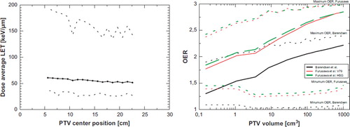
The dose averaged LET of a 5 × 5 × 5 cm3 PTV as a function of position throughout the water phantom, shows only a small decrease. More secondary low-LET fragments from inflight nuclear reactions, are created along increasing depth, which dilutes the higher LET found in the spread out Bragg peak. The effect is not very pronounced though: the dose-average LET of the entire PTV ranges from 60 keV/μm if the PTV centre is located 6 cm inside the water phantom, and 50 keV/μm if the PTV centre at a depth of 23 cm. The minimum and maximum LET encountered in a voxel element inside the PTV span a range of 36–192 keV/μm at the position close to the surface. The span is large due to the well known sharp increase in LET at the distal edge of the spread out Bragg peak. At the deepest position, the dose average LET spans 23–143 keV/μm in the PTV. Note that the highest LET of the beam is found just outside the PTV. Therefore some fluctuations are encountered in the maximum LET value inside the PTV, which is attributed to the steep LET gradient at the distal edge of the SOBP combined with effects arising from the discrete nature of the phantom being divided in 1 mm3 voxels.
In we plot the dose averaged LET as a function of PTV volume. For larger volumes the LET is quickly diluted. Translating the LET to OER using the data from Barendsen et al. and Furusawa et al. produces the OER curves also shown in . Obviously the resulting OER strongly depends on the respective cell line, but even more interesting is the large span of OER values found in the PTV. The average OER strongly depends on the volume, quickly reducing for smaller volumes. The bulk of the PTV is far from OER 1, which indicates that the LET of carbon ions is not high enough to eliminate radio resistance from hypoxia. A solution could be either to increase the LET by using particles heavier than 12 carbon ions. Unfortunately this also increases the RBE for late damage in normal tissue. This leads to the idea of reducing the size of the high-LET volume and confine these to the small volumes identified as being hypoxic, while use low-LET radiation elsewhere.
Figure 1. Left: Dose average LET as a function of volume. Dotted curves show the minimum and maximum dose averaged LET per voxel in the PTV. Right: LET translated to OER using three different cell lines.
In show dose maps of the configuration 1a and 1b as described in the materials and methods section. Here it becomes very obvious that even quite equal dose distributions can produce very different ET distributions. Just by stacking four equal SOBPs, each covering the entire SOBP, the high-LET region is found at the edge of the PTV. However, using four “half fields”, we can concentrate LET in the intersection of the distal SOBPs from each field. Applying techniques using multiple fields, or even continuous gantry angles (e.g. intensity modulated particle arc-therapy) can result in concentrating high-LET distributions at any arbitrary point in the PTV.
Figure 2. Left column: Configuration 1a. Four flat carbon ion fields. High-LET is distributed on the distal edge of the SOBPs. Right column: Configuration 1b. We here demonstrate “LET-painting”. Four “half PTV”s are used instead, which gives a very different LET and therefore a very different OER distribution – even if the dose distribution is rather equal. “ct [mm]” marks the position in mm along the x and y direction.
![Figure 2. Left column: Configuration 1a. Four flat carbon ion fields. High-LET is distributed on the distal edge of the SOBPs. Right column: Configuration 1b. We here demonstrate “LET-painting”. Four “half PTV”s are used instead, which gives a very different LET and therefore a very different OER distribution – even if the dose distribution is rather equal. “ct [mm]” marks the position in mm along the x and y direction.](/cms/asset/9d0594cc-3c2c-4614-8149-34bd64dd472f/ionc_a_510640_f0002_b.jpg)
is a demonstration of how carbon ions (and in principle other heavy charged particles) can be used for not only dose escalation in distinct tumour compartments, but also LET boost. Boosting the PTV with either proton or carbon ions may result in two similar dose distributions but very different LET distributions. The resulting OER distribution is naturally also quite different.
Figure 3. Three figures showing the dose, LET and OER of a 10 cm diameter target volume irradiated with protons to 50% dose. The proton beam is entering from the top. Inside the large spherical PTV a 50% boosts are given to two smaller spherical targets of 1 cm diameter. The lower target is irradiated with protons (beam entering from the right) and the upper target is irradiated with carbon ions (beam entering from the right), recognized by the characteristic fragmentation tail. “ct [mm]” marks the position in millimeters in x and y direction.
![Figure 3. Three figures showing the dose, LET and OER of a 10 cm diameter target volume irradiated with protons to 50% dose. The proton beam is entering from the top. Inside the large spherical PTV a 50% boosts are given to two smaller spherical targets of 1 cm diameter. The lower target is irradiated with protons (beam entering from the right) and the upper target is irradiated with carbon ions (beam entering from the right), recognized by the characteristic fragmentation tail. “ct [mm]” marks the position in millimeters in x and y direction.](/cms/asset/8ec23121-4728-4825-b066-bf4104ae838e/ionc_a_510640_f0003_b.jpg)
Multi-modal irradiation can help to reduce unwanted high-LET radiation in normal tissue and extent tumour regimes, where the advantage from fractionation effects should be maintained. Using fractionated treatment from either protons or photons provides the knowledge of one century of clinical experience. The skin sparing effect from x-ray buildup and better robustness with concern to intra and inter fractional organ motion and setup errors advocate the use of both high- and low-LET irradiation. Similar arguments also motivated the research of pion and antiproton therapy [Citation26–29], which also feature a low RBE in the entry region of the beam and an elevated LET and RBE in the peak region. However the maximal LET and RBE achieved in antiproton beams may be somewhat limited [Citation30], and is most likely to be found somewhere in between that of protons and carbon ions [Citation27].
Thus, heavy charged particles such as carbon ions or heavier particles can be used for not only dose escalation in distinct tumour compartments, but also LET boost as earlier mentioned in . Reducing the field size of a carbon ion beam increases the dose average LET found in its target volume, but it may still be insufficient if one wishes to achieve a low OER. Increasing LET by increasing the charge of the particle type has several disadvantages, as the advantageous depth-dose curve deteriorates for heavier particles, due to primary particle fragmentation, and the increased risk of morbidity in normal tissue. However, these effects may be limited if one keeps the volumes irradiated with high-LET radiation small, and apply low-LET radiation to the rest of the tumour volume.
The first strategy shown in demonstrating LET-painting with a single ion species, will in practice be difficult to realise, since fields must be positioned back-to-back of each other. The range prediction in clinical particle therapy settings is often with higher uncertainty than laterally. One may expect that multi-modal dose and LET-painting will produce more robust plans.
One may question, whether reliable OER data can be found, which here is used as an input parameter for dose and LET-painting. Since achieved tumour control is a stochastic process, one could argue that exact OER data may not be essential: in principle any LET and/or dose escalation in a hypoxic entity while maintaining the dose in the normal tissue would lead to a therapeutic advantage with dose and LET-painting.
Conclusion
We show that according to in vitro cell data, the reduced OER effect of carbon ions is expected to be rather limited. Typical treatment volumes show only an elevated LET at the distal edge of the SOBPs, and the dose average LET found in carbon ion SOBPs is quickly reduced as a function of treatment volume. Two strategies are presented how to overcome this problem: for mono-modality treatment, high-LET regions can in principle be placed in hypoxic tumour compartments, however we expect that this strategy will be very susceptible to uncertainties in particle range. The secondary strategy relies on the observation that on a reduction of the PTV size of carbon ion fields, the dose average LET significantly increases, and can be more effectively used as a ”LET boost” on hypoxic tumour compartments. The dose-average LET though does not depend strongly on the depth of the PTV though. High-LET radiation is combined with low-LET radiation for an LET boost (and possibly dose boost) seem more robust, but calls for multi-modal treatment planning systems.
Ideally, a treatment planning system should include OER effects in the radiobiological optimisation. The optimisation process should not be limited to finding a fluence of a selected beam (resulting in a given dose), but should also optimise on beam type: Mixing photons or protons with heavier ions can craft arbitrary LET distributions, and the optimisation routine should eventually identify the most favourable multi-modal treatment plan. Naturally, this calls for more research in order to quantify the therapeutic advantage gained hereby, and then again, this should eventually be followed by clinical studies.
Acknowledgements
This work is supported by the Danish Cancer Society (http://www.cancer.dk), and the Lundbeck Foundation Centre for Interventional Research in Radiation Oncology (http://www.cirro.dk).
Declaration of interest: The authors report no conflicts of interest. The authors alone are responsible for the content and writing of the paper.
References
- Suit H, DeLaney T, Goldberg S, Paganetti H, Clasie B, Gerweck L, . Proton vs carbon ion beams in the definitive radiation treatment of cancer patients. Radiother Oncol 2010;95:3–22.
- IAEA. Relative biological effectiveness in ion beam therapy. International Atomic Energy Agency; 2008. 461. Technical Report Series.
- Wilkens JJ, Oelfke U. Direct comparison of biologically optimized spread-out Bragg Peaks for protons and carbon ions. Int J Radiat Oncol Biol Phys 2008;70:262–6.
- Elsässer T, Kräemer M, Scholz M. Accuracy of the local effect model for the prediction of biologic effects of carbon ion beams in vitro and in vivo. Int J Radiat Oncol Biol Phys 2008;71:866–72.
- Nordsmark M, Overgaard J. A confirmatory prognostic study on oxygenation status and loco-regional control in advanced head and neck squamous cell carcinoma treated by radiation therapy. Radiother Oncol 2000;57:39–43.
- Nordsmark M, Bentzen SM, Rudat V, Brizel D, Lartigau E, Stadler P, . Prognostic value of tumor oxygenation in 397 head and neck tumors after primary radiation therapy. An international multi-centre study. Radiother Oncol 2005;77: 18–24.
- Toma-Das I, Daşu A, Brahme A. Dose prescription and optimisation based on tumour hypoxia. Acta Oncol 2009;48: 1181–92.
- Overgaard J. Hypoxic radiosensitizazion: Adored and ignored. J Clin Oncol 2007;25:4066–74.
- Ling CC, Humm J, Larson S, Amols H, Fuks Z, Leibel S, . Towards Multidimensional Radiotherapy (MD-CRT): Biological imaging and biological conformality. Int J Radiat Oncol Biol Phys 2000;47:551–60.
- Tanderup K, Olsen DR, Grau C. Dose painting: Art or science? Radiother Oncol 2006;79:245–8.
- Thorwarth D, Soukup M, Alber M. Dose painting with IMPT, helical tomotherapy and IMXT: A dosimetric comparison. Radiother Oncol 2008;86:30–4.
- Thorwarth D, Alber M. Implementation of hypoxia imaging into treatment planning and delivery. Radiother Oncol 2010 (in press).
- Kim Y, Tomé WA. Dose-painting IMRT optimization using biological parameters. Acta Oncol 2010;Epub ahead of print:1–11.
- Bentzen S. Theragnostic imaging for radiation oncology: Dose-painting by numbers. Lancet Oncol 2005;6:112–7.
- Barendsen GW, Koot CJ, van Kersen GR. The effect of oxygen on impairment of the proliferative capacity of human cells in culture by ionizing radiations of different LET. Int J Rad Biol 1966;10:317–27.
- Furusawa Y, Fukutsu K, Aoki M, Itsukaichi H, Eguchi-Kasai K, Ohara H, . inactivation of aerobic and hypoxic cells from three different cell lines by accelerated 3He, 12C and 20Ne-ion beams. Radiat Res 2000;154:485–96.
- Wambersie A, Richard F, Breteau N. Development of fast neutron therapy worldwide. Radiobiological, clinical and technical aspects. Acta Oncol 1994;33:261–74.
- Koh W, Griffin T, Laramore G, Stelzer K, Russell K. Fast neutron radiation therapy. Results of phase III randomized trials in head and neck, lung, and prostate cancers. Acta Oncol 1994;33:293–8.
- Svensson H, Landberg T. Neutron therapy – The historical background. Acta Oncol 1994;33:227–31.
- Schwarz R, Krüll A, Heyer D, Baumann M, Schmidt R, Hübener KH. Present results of neutron therapy: The German experience. Acta Oncol 1994;33:281–7.
- Warenius HM. Fast neutron therapy: The UK experience. Acta Oncol 1994;33:289–92.
- Goitein M. Trials and tribulations in charged particle radiotherapy. Radiother Oncol 2010;95:23–31.
- Krämer M, J kel O, Haberer T, Kraft G, Schardt D, Weber U. Treatment planning for heavy-ion radiotherapy: Physical beam model and dose optimization. Phys Med Biol 2000; 45:3299–317.
- Krämer M, Scholz M. Treatment planning for heavy-ion radiotherapy: Calculation and optimization of biologically effective dose. Phys Med Biol 2000;45:3319–30.
- Weber U, Kraft G. Design and construction of a ripple filter for a smoothed depth dose distribution in conformal particle therapy. Phys Med Biol 1999;44: 2765–75.
- Hall EJ, Astor M. The oxygen enhancement ratio for negative pi mesons. Int J Radiat Oncol Biol Phys 1978;5:55–60.
- Holzscheiter MH, Bassler N, Agazaryan N, Beyer G, Blackmore E, DeMarco JJ, . The biological effectiveness of antiproton irradiation. Radiother Oncol 2006;81:233–42.
- Bassler N, Alsner J, Beyer G, DeMarco JJ, Doser M, Hajdukovic D, . Antiproton radiotherapy. Radiother Oncol 2008;86:14–9.
- Bassler N, Kantemiris I, Engelke J, Holzscheiter M, Petersen JB. Comparison of optimized single and multifield irradiation plans of antiproton, proton and carbon ion beams. Radiother Oncol 2010;95:87–93.
- Bassler N, Holzscheiter MH. Calculated LET spectrum from antiproton beams stopping in water. Acta Oncol 2009;48:223–6.