Abstract
Objective: Recovering tissue deformation during robotic-assisted minimally invasive surgery (MIS) is an important step towards motion compensation and stabilization. This article presents a practical strategy for dense 3D depth recovery and temporal motion tracking for deformable surfaces.
Methods: The method combines image rectification with constrained disparity registration for reliable depth estimation. The accuracy and practical value of the technique are validated using a tissue phantom with known 3D geometry and motion characteristics and in vivo data.
Results: Results from the phantom model correctly follow the motion trend indicated from the ground truth provided by CT scanning, and regression analysis shows the intrinsic accuracy that can be achieved with the proposed technique. Results applied to in vivo robotic-assisted MIS data are also provided, indicating the practical value of the proposed method.
Conclusion: The proposed method presents a practical strategy for dense depth recovery of surface structure in robotic-assisted MIS that incorporates stereo vision. Results on phantom and in vivo data indicate the quality of the method and also highlight the importance of further considering the effects of specular highlights.
Introduction
With recent advances in robotic-assisted minimally invasive surgery (MIS), it is now possible to perform closed-chest cardiothoracic surgery on a beating heart to minimize patient trauma and certain side effects of cardiopulmonary bypass. For robotic-assisted MIS, dexterity is enhanced by microprocessor-controlled mechanical wrists, which allow motion scaling for reducing gross hand movements and the performance of micro-scale tasks that are otherwise not possible. Thus far, two commercial master–slave manipulators are available Citation[1]. They are specifically designed for MIS cardiac surgery but are increasingly being used in a variety of other surgical procedures. Both systems improve the ergonomics of laparoscopic surgery and provide high dexterity, precision, and 3D visualization of the operating field. One of the significant challenges of beating heart surgery is the destabilization introduced by cardiac and respiratory motions, severely affecting precise instrument–tissue interactions and the execution of complex grafts. Mechanical stabilizers Citation[2] permit off-pump procedures by locally stabilizing the target area while the rest of the heart supports blood circulation. Despite this, residual motion remains, which complicates delicate tasks such as small vessel anastomosis. These problems are compounded with the reduced access to the internal anatomy inherent in MIS, which imposes difficulties on target localization and on the use of tactile feedback to actively constrain surgical actions.
Thus far, a number of techniques have been proposed for resolving intraoperative tissue deformation, and Trejos et al. Citation[3] investigated the feasibility of providing motion compensation by analyzing the performance of a suture simulation task with motion compensation support. Intraoperative medical imaging techniques potentially offer precise information about soft tissue morphology and structure, but they introduce significant challenges to instrument design, integration, and computational cost. Magnetic resonance imaging (MRI)-compatible robots require non-ferromagnetic components suitable for use within a high-strength magnetic field and represent an emerging field of research Citation[4]. Currently, a more practical alternative is to use optical-based techniques to infer surface deformation in real-time. In animal experiments, Nakamura et al. Citation[5] used a high-speed camera to track a fiducial marker on the epicardial surface. The trajectory changes of the markers were used to identify the frequencies due to cardiac and respiration motions by using an autoregressive model. Similarly, Ginhoux et al. Citation[6] used a high-speed camera to track four LEDs mounted on the epicardial surface in both phantom model and animal experiments. Hoff et al. Citation[7] recovered the motion of a beating heart in a porcine study, where two dual-axis accelerometer sensors were sutured to the outer heart wall. Thrakal et al. Citation[2] used a fiber-optic displacement sensor to measure the motion of a rat's chest for motion modeling with weighted time series. A region-based, reduced-affine tracking model was used by Gröger et al. Citation[8] in robotic-assisted MIS heart surgery for computing the local motion of the epicardial surface. The sensitivity of the method to features created at the boundaries of specular reflections was reduced by pre-processing. Although these techniques demonstrate the feasibility of providing motion compensation, they generally do not consider detailed 3D deformation. Furthermore, in practical surgical procedures, it is not desirable to introduce additional tracking equipment such as a laser range finder or place fiducial markers on the anatomical regions of interest.
With the use of a stereoscopic laparoscope for robotic-assisted MIS cardiac surgery, the feasibility of recovering the 3D structure of the operating field based on computer vision techniques has also been investigated. Mourgues et al. Citation[9] used a correlation-based computational stereo algorithm in combination with a learning process to remove the laparoscopic instruments and to build a model of the epicardial surface. The method was later used as a part of an image-based guidance framework Citation[10]. Lau et al. Citation[11] used a spline surface representation in an iterative registration framework to track the motion of the disparity map in an animal experiment. Previously, monocular shading was used to infer surface shape in less interactive endoscope diagnostic procedures for tumor detection Citation[12]. Deligianni et al. Citation[13] also used a linear shape-from-shading method to infer pq surface shape for registering endoscopic video to prior tomographic data. Although the recovery of the depth of a 3D scene based on different visual cues is one of the classic problems of computer vision, dense disparity measurement for deformable structure with high specularity is a difficult task. For monocular techniques based on shading, the complex reflectance functions of the wet tissue render the conventionally imposed constraints error-prone. In the stereoscopic case, the homogenous textures and view-dependent appearance of surfaces limit the discriminatory capabilities of similarity metrics used by computational stereo algorithms. Furthermore, with the view of the scene limited by the laparoscope trocar and the continuous deformation of the tissue, linking multi-view constraints spatially and temporally is difficult with conventional methods.
The purpose of this article is to present a robust dense 3D depth recovery method with a stereoscopic laparoscope for motion stabilization. By calibrating the cameras prior to image acquisition, the epipolar constraint can be imposed through image rectification to limit the search space for stereo correspondence. A hierarchical multi-resolution registration algorithm imposing inherent smoothness on the recovered disparity is used to resolve the resulting 1D matching problem. The accuracy and practical value of the technique are validated using a silicone tissue phantom with known 3D geometry and motion characteristics. Example results of the technique applied to in vivo robotic-assisted MIS data are also provided.
Methods
The proposed method consists of the following steps: calibration of the stereo laparoscope using a well known photogrammetry-based method with a planar calibration object; image rectification to restrict the search space for stereo correspondence to a 1D image scanline; and registration of stereo images to recover a dense disparity map and thus, by triangulation, a dense 3D reconstruction of the soft tissue in the operating field. In the following sections each step is discussed in more detail.
Stereo camera model and calibration
One of the first steps towards depth recovery is to compute both the intrinsic and extrinsic camera parameters of the stereoscopic laparoscope. In this study, the standard pinhole model is assumed, and the projection of a 3D world point M = [X Y Z 1]T to the image point m = [x y 1]T is described up to a scale factor s by a matrix multiplication in homogeneous coordinates as sm = PM. The camera projection matrix P can be decomposed into an upper triangular matrix K describing the internal optics of the camera, a rotation matrix R, and translation vector t representing the camera's position and orientation with respect to a world coordinate system. The camera projection matrix can thus be defined as:
Without a loss of generality, the camera matrices for the stereoscopic laparoscope can be canonically represented by the following equations by taking the left camera's optical center to coincide with the origin of the world coordinate system and the left optical axis to be collinear with the world Z axis:
In practice, laparoscope cameras can deviate considerably from the ideal perspective projection and induce a high level of distortion. We consider henceforth the lens distortion model proposed by Hekkila et al. Citation[14] by using the first three terms of the radial distortion, ,
, and
, and two tangential distortion terms,
and
, to correct ideally projected points to the observed image points.
For robotic-assisted MIS, the stereo cameras are usually pre-calibrated during the preparation of the robotic system and then remain unchanged during the surgical procedure. Off-line photogrammetry-based calibration by using objects with known geometry is therefore sufficient Citation[15]. In this study, the intrinsic and extrinsic parameters of the cameras were derived by using a planar calibration grid shown in and a closed form solution linking constraints from the homography between the calibration and image planes as proposed by Zhang Citation[16]. Following the initial estimate computed from a minimum of five different views, the parameters were refined subject to the mean squared error between the measured image points and the re-projected world points Mi. By parameterizing the rotation matrix R to reduce the number of unknowns as a vector of three parameters r using the Rodrigues formula, the minimization criteria for a set of n images with m grid points can be written as:
Figure 1. An image of the planar calibration grid used for estimating the camera parameters. The stereo endoscope was kept static while the calibration object was shown in several arbitrary positions in front of the cameras. [Color version available online]
![Figure 1. An image of the planar calibration grid used for estimating the camera parameters. The stereo endoscope was kept static while the calibration object was shown in several arbitrary positions in front of the cameras. [Color version available online]](/cms/asset/3e1ffc26-ebe8-428e-9a80-85050326144a/icsu_a_123020_f0001_b.jpg)
The optimization problem formulated previously is non-linear, and the Levenberg–Marquardt algorithm was used to derive the aforementioned parameters iteratively (further resources and an implementation of this calibration method using gradient descent minimization are available online at www.caltech.edu/bouget/calib). After each camera has been calibrated, the relative pose of the two cameras is then introduced such that the following equation is minimized. This allows the use of the solution derived for each individual camera as the initial solution for the Levenberg–Marquardt algorithm.
The minimization process in Equation (4) refines the intrinsic parameters of each camera and determines the relative extrinsic parameters of the stereo laparoscope. The number of variables for each view of the calibration object is reduced because only the extrinsic parameters of the reference camera change and the relative extrinsics are used to determine the projection to the other camera.
Image rectification
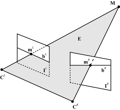
The projections of a 3D world point in the left and right image planes are geometrically related through the epipolar geometry, which imposes an inherent constraint on the respective image locations of the projected points Citation[17]. Any 3D point in the scene M defines a plane E with the two camera centers CL and CR intersecting the images at two corresponding epipolar lines bL and bR as shown in . Points lying on an epipolar line in one image must also be on the matching epipolar line in the other image, which means that the search space for finding corresponding points in the stereo pair is reduced from 2D to 1D. Image rectification is the process of transforming a stereo image pair based on the known epipolar geometry to horizontally align corresponding epipolar lines with image scanlines. Once images are rectified in this form, it is possible to implement stereo-matching algorithms taking advantage of the epipolar constraint in a more efficient manner.
Figure 2. The epipolar geometry between the stereo cameras reduces the stereo-matching search space to corresponding epipolar lines.
For common robotic MIS settings, the cameras are slightly verged to permit both positive and negative disparities so as to enhance the overall 3D depth perception. To ease the fusion of the stereo images for the observer, the stereo cameras are generally in near-vertical alignment. This arrangement, however, may not be perfect in practice and therefore image rectification is necessary. To alleviate this problem, a rectification process for fully calibrated cameras Citation[18] is applied to the stereo image pairs before dense correspondence is sought. After the rectifying transformations, the intrinsic parameter matrices of the two rectified cameras must be the same by definition. Without changing the centers of the cameras, the new projection matrices can be defined through the same rotation matrix such that
In the aforementioned equation, Rr may be computed by assuming that the new image planes are parallel to the baseline. As the camera centers remain unchanged, so does the optical ray through each image point. The original and rectified camera matrices can therefore be written as:
Subsequently, the rectifying transformations used to map standard image points onto the rectified image plane can be computed from the original and rectified camera matrices through the following pair of equations by using λk to denote scale:
This method does not directly minimize the distortion or resampling effects caused by the transformations Citation[19]. However, in the context of the current work, the warping introduced previously is inherently small because of the fully calibrated set-up and the general settings of the stereoscopic laparoscope cameras as shown in .
Figure 3. (a) A standard laparoscopic image as viewed by the surgeon. (b) Rectified image as used by the registration algorithm. The warping between introduced and rectified image is visibly small. [Color version available online]
![Figure 3. (a) A standard laparoscopic image as viewed by the surgeon. (b) Rectified image as used by the registration algorithm. The warping between introduced and rectified image is visibly small. [Color version available online]](/cms/asset/181be0f9-85d6-4dcd-9127-4e50d73eede9/icsu_a_123020_f0003_b.jpg)
Stereo correspondence with constrained disparity registration
Traditional computer vision techniques for dense stereo correspondence are mainly concerned with static, rigid objects, and much emphasis is placed on issues related to occlusion and discontinuity Citation[20]. Occlusion and object boundaries make stereo matching a difficult optimization problem, as disparity is not globally continuous and smooth. Existing techniques include sliding windows, graph-cuts, and dynamic programming approaches Citation[21]. Computational stereo methods can also make explicit assumptions on the shape of the observed surfaces Citation[22]. This can be necessary to resolve the underconstrained nature of the matching process, especially in the presence of homogeneous textures, which reduce the discriminatory capabilities of the similarity measure.
For soft tissue, as observed in MIS, the surface is generally smooth and continuous. Therefore, occlusion and discontinuity may be assumed to be negligible. The difficulty of dense depth recovery is usually due to the paucity of identifiable landmarks and the view-dependent properties of the wet tissue. Explicit geometrical constraints of the deformation model are therefore required to ensure the overall reliability of the algorithm. In this study, the free-form registration framework proposed by Veseer et al. Citation[23] was used as it provides a robust, fully encapsulated multi-resolution approach based on piece-wise bilinear maps (PBM). The lattice of PBM permits non-linear transitions, which are suitable for temporally deforming surfaces, and it easily lends itself to a hierarchical implementation. With image rectification, the search space for spatial registration is constrained on scan lines, and the number of PBM forming the image transformation is increased, refining the registration of finer structures. Within this framework, the disparities obtained at low resolution levels are propagated to higher levels and used as starting points for the optimization process. shows the evolution of the PBM grid at the multiple resolution levels and the corresponding disparity map for each resolution.
Figure 4. Several iterations of the registration algorithm showing the evolving PBM lattice and the resulting depth map image. [Color version available online]
![Figure 4. Several iterations of the registration algorithm showing the evolving PBM lattice and the resulting depth map image. [Color version available online]](/cms/asset/e9fbef4d-aea7-4465-ad6f-effea132f03e/icsu_a_123020_f0004_b.jpg)
To cater for surfaces in laparoscope images, which have reflectance properties dependent on the viewing position, normalized cross correlation (NCC) was used as a similarity measure. The NCC of two image regions IL and IR of dimensions (u, v) is defined as:
For deriving disparity values of the soft tissue, the gradient of the given metric can be computed directly, which permits the use of fast optimization algorithms. For this study, the Broyden–Fletcher–Goldberg–Shano method can be used. This is a quasi-Newton technique, which uses an estimate of the Hessian to speed up the iterative process Citation[24].
Temporal correspondence
For deriving detailed motion characteristics of the deforming surface, the temporal correspondence of the surface points was obtained. The registration framework mentioned previously was used without confining the search space to 1D, because temporal non-rigid motion does not conform to the epipolar geometry between time-consecutive images. By permitting horizontal and vertical displacements of the PBM control points, the method facilitates the detection of image changes due to surface deformations, and the NCC provides a metric that is robust to view dependency.
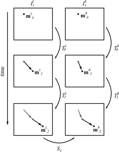
To enhance the robustness of the temporal tracking process, both the left and right images were temporally registered, and the transformation with the best similarity score was selected. The motion of the image points can then be tracked temporally in 3D by traversing the collected PBM lattice transformations from the spatial St and temporal registration. This process is necessary for determining the 3D motion of points on the soft tissue surface, whose movement is not restricted to the disparity space determined through stereo correspondence. shows a schematic diagram of this approach.
Figure 5. A schematic illustration of the system for tracking the temporal 3D motion of a surface point by traversing through the temporal and spatial registration transformations St and .
Specular highlight correction
Specular highlights in computational stereo have generally been addressed as a source of error, and methods to minimize their effects through polarization and light source adjustment Citation[25] have been investigated. More recently, a method was proposed by exploiting the movement of highlights in the epipolar plane image formed by a moving camera Citation[26]. In laparoscopic images, Gröger et al. Citation[27] removed specularities by using interpolation and iterative diffusion in a pre-processing step to improve a motion tracking scheme. For the method proposed in this article, a simple algorithm for reducing the effects of large highlights was used, which involved the following steps: (i) detecting the highlight using thresholding of the intensity and saturation, (ii) identifying the control points in the PBM lattice which have been affected, and (iii) bilinearly interpolating information from the surrounding control points to remove errors.
Experimental design and validation
The proposed method was implemented in C + +on a conventional PC machine (2-GHz Intel Pentium III processor and 512 MB of main memory with Windows 2000 operating system). To model the real stereoscopic laparoscope, a stereo camera rig was built by using a pair of miniature CMOS and NTSC standard cameras. Each camera has a physical diameter of just over 5 mm, and it was therefore possible to set up a configuration with a small baseline of just over 5 mm. The described calibration procedure was employed by using a 5 × 7 square grid with a checked black and white pattern. Corners were detected through a fully automated procedure, where image processing, edge detection, and line fitting are used to locate the calibration grid points up to sub-pixel accuracy. The pixel re-projection error after calibration was measured at less than half a pixel. We also measured the reconstruction error of the calibration object after triangulation at an average magnitude of 1 mm. For this study, we used a least squares triangulation method solved with the singular value decomposition. For robustness in the presence of noise, triangulation can be improved by taking into account errors in the measured coordinates and refining the measurements subject to the epipolar geometry Citation[17].
To assess the accuracy of the proposed algorithm, a tissue phantom made of silicone rubber and painted with acrylics was constructed and mounted onto a fixed solid frame. The surface was coated with silicone rubber mixed with acrylic to give it a specular finish that looks similar to wet tissue. A tomographic model of the phantom was scanned with a Siemens Somaton Volume Zoom four-channel multi-detector CT scanner with a slice thickness of 0.5 mm and in-plane resolution of 1 mm. To allow the evaluation of temporal surface deformation, the model was scanned at four discrete and reproducible deformation levels controlled by a manual pulley system, while the solid base remained fixed. illustrates a pair of images captured by the stereo cameras and cross-sectional images of two different time frames of the tissue phantom captured by CT scanning. The corresponding 3D surface plots, which also indicate the approximate dimensions of the silicone surface, and the range of applied deformation are shown in and , respectively.
Figure 6. (a and d) Images from the left camera of the stereo rig. (b and e) Two slices from the CT scan at different levels of surface deformation. (c and f) Corresponding 3D plots of the full phantom model surface as reconstructed from the CT data. [Color version available online]
![Figure 6. (a and d) Images from the left camera of the stereo rig. (b and e) Two slices from the CT scan at different levels of surface deformation. (c and f) Corresponding 3D plots of the full phantom model surface as reconstructed from the CT data. [Color version available online]](/cms/asset/b1a98c75-8a81-40db-afbf-1a88b1975cd4/icsu_a_123020_f0006_b.jpg)
Results
shows 3D plots of the reconstructed surfaces at four different levels of deformation as captured by CT and the proposed algorithm for dense 3D depth recovery. The correct trend of surface displacement is captured by the proposed method, as the magnitude and order of the results are in agreement with the ground truth derived from CT. The variation in surface shape between the two methods is mostly due to the reduced resolution of the stereo approach and the inherent smoothing effect of the PBM registration algorithm.
Figure 7. The reconstructed 3D surface for four different levels of deformation as captured by 3D CT (a) and the proposed depth recovery method based on combined image rectification and constrained disparity registration (b). [Color version available online]
![Figure 7. The reconstructed 3D surface for four different levels of deformation as captured by 3D CT (a) and the proposed depth recovery method based on combined image rectification and constrained disparity registration (b). [Color version available online]](/cms/asset/432b1550-1332-45c3-aee3-af48ad5af190/icsu_a_123020_f0007_b.jpg)
– demonstrate the regression of relative depth changes over time between the surfaces as extracted by the two techniques and shown in . It is evident that the overall quality of the stereo reconstruction is good, but the scatter plots also show a certain level of deviation. This is to be expected, as the high-resolution CT reconstruction contains a level of detail that is beyond the intrinsic resolution that can be recovered by using binocular stereo. A further source of error was due to the specular highlights, which were not explicitly modeled or removed in the proposed method.
Figure 8. Scatter plots (a)–(c) illustrate the correlation of the recovered depth change between different levels of deformation by the CT and the proposed technique. [Color version available online]
![Figure 8. Scatter plots (a)–(c) illustrate the correlation of the recovered depth change between different levels of deformation by the CT and the proposed technique. [Color version available online]](/cms/asset/4fa8d163-96e4-4699-ab34-b33574dedb23/icsu_a_123020_f0008_b.jpg)
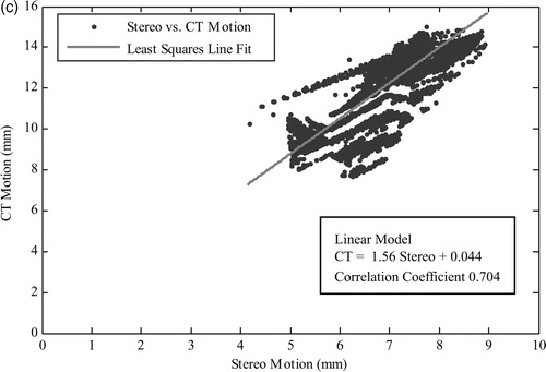
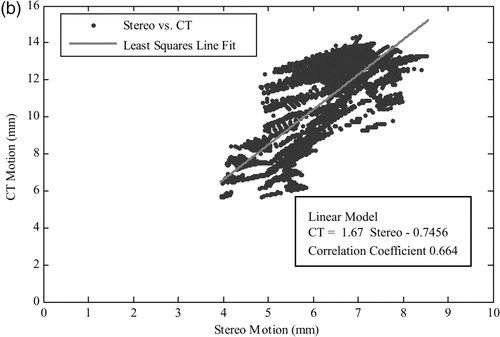
shows the analysis of the regression between the computed surface motion and the ground-truth CT data. The calculated correlation coefficients conform to our observations in , indicating a correct regression trend but also highlighting the associated deviations in the results. It is worth noting that the mean error reported in is scaled up due to the size of the phantom experiment, which is approximately five orders of magnitude larger than the in vivo dimensions. It is also worth noting that the standard deviation of error is heavily influenced by the inherent smoothness of the PBM registration algorithm.
Table I. Evaluation of the regression between the recovered motion and the ground-truth CT motion for the scaled-up phantom constructed for this study.
To demonstrate the potential clinical value of the proposed technique, illustrates the reconstructed depth map from an in vivo stereoscopic laparoscope sequence. Both the depth maps and the associated 3D renditions illustrate the quality of the reconstruction technique. However, it is also apparent that specular highlights represent a major problem for the proposed algorithm, as evident from the reconstruction errors indicated by the arrows. In such largely homogeneous regions, specularities influence the registration algorithm by acting as virtual features, which do not correspond to any point on the tissue surface. illustrates the control points identified by the proposed specular removal method and the resulting reconstruction after interpolating more reliable information onto them. It is evident that the large deviation in the reconstruction is significantly reduced.
Figure 9. A pair of stereo-images (a and e) from an in vivo stereoscopic laparoscope sequence and three temporal frames of the reconstructed depth map (b–d) and their corresponding 3D rendering results (f–h). Arrows indicate visible errors in the recovered depth due to specular highlights. [Color version available online]
![Figure 9. A pair of stereo-images (a and e) from an in vivo stereoscopic laparoscope sequence and three temporal frames of the reconstructed depth map (b–d) and their corresponding 3D rendering results (f–h). Arrows indicate visible errors in the recovered depth due to specular highlights. [Color version available online]](/cms/asset/7f9439cf-fa81-4b7f-8534-f80d94861c9f/icsu_a_123020_f0009_b.jpg)
Figure 10. (a) A laparoscopic image where specular highlights have been detected through thresholding. (b) Corresponding PBM lattice where control points affected by a large specular highlight have been highlighted. (c) The 3D rendering result of the reconstruction after interpolating across erroneous control points. [Color version available online]
![Figure 10. (a) A laparoscopic image where specular highlights have been detected through thresholding. (b) Corresponding PBM lattice where control points affected by a large specular highlight have been highlighted. (c) The 3D rendering result of the reconstruction after interpolating across erroneous control points. [Color version available online]](/cms/asset/ac27aedf-3ed6-467f-bf55-43b9a9139df0/icsu_a_123020_f0010_b.jpg)
Discussion and conclusion
In this article, we have developed a practical strategy for dense 3D structure recovery and temporal motion tracking for deformable surfaces. The purpose of the study is to capture real-time surface deformation during robotic-assisted MIS procedures such that effective motion stabilization can be deployed. The method uses image rectification to simplify the subsequent free-form disparity registration procedure. Both phantom validation and in vivo results demonstrate the potential clinical value of the technique.
The use of image rectification combined with stereo-correspondence with constrained disparity registration has been shown to provide consistent results in both phantom and in vivo experiments. The performance of the method, however, is dependent on the handing of specular highlights before depth reconstruction. This is because in the absence of sufficient textural information, the virtual features can cause misleading maxima in the similarity metric. In this article, we have used a simple filtering method for removing specularities, and for tissue with smooth deformation the method is proven to be relatively effective. However, it should be noted that this approach effectively reduces the spatial resolution of the method, and therefore more intuitive handling of difficult reflection components is necessary. For robotic-assisted MIS procedures, it is possible to exploit the restricted lighting configuration imposed by the laparoscope to filter out these artefacts and to use their motion to infer further information of the surface shape.
Further investigation is required to determine the processing requirements necessary to deploy the proposed method in a surgical system. The current algorithm can achieve ∼0.25 Hz on a standard 2-GHz Intel Pentium III machine. However, this can be improved significantly by using a parallel processing architecture or a dedicated GPU implementation to achieve real-time performance. We are also performing comprehensive comparative studies with existing stereo-correspondence algorithms and investigating suitable techniques to address error propagation within the proposed system.
Acknowledgements
The authors would like to acknowledge the financial support from the EPSRC, the Royal Society, and the Wolfson Foundation.
References
- Ballantyne G. Robotic surgery, telerobotic surgery, telepresence, telementoring. Surg Endosc 2002; 2: 1389–1402
- Thrakal A, Wallace J, Tomlin D, Seth N, Thakor N (2001) Surgical motion adaptive robotic technology (SMART): taking the motion out of physiological motion. Proceedings of the Fourth International Conference on Medical Image Computing and Computer-Assisted Intervention (MICCAI 2001), UtrechtNetherlands, September, 2001, W J Niessen, M A Viergever. Springer, Berlin, 317–325
- Trejos A, Salcudean S, Sassani F, Lichtenstein S (1999) On the feasibility of a moving support for surgery on the beating heart. Proceedings of the Second International Conference on Medical Image Computing and Computer-Assisted Intervention (MICCAI 1999), CambridgeUK, September, 1999, C Taylor, A C. F Colchester. Springer, Berlin, 1088–1097
- Taylor R H, Stoianovici D. Medical robotics in computer-integrated surgery. IEEE Trans Robot Autom 2003; 19: 765–781
- Nakamura Y, Kishi K, Kawakami H. Heartbeat synchronization for robotic cardiac surgery. IEEE International Conference on Robotics and Automation (ICRA 2001), SeoulKorea, 2014–2019, IEEE 2001
- Ginhoux R, Gangloff J A, Mathelin M F (2004) Beating heart tracking in robotic surgery using 500 Hz visual servoing, model predictive control and an adaptive observer. IEEE International Conference on Robotics and Automation (ICRA 2004), New OrleansUSA, April, 2004, 274–279, IEEE
- Hoff L, Elle O J, Grimnes M J, Halvorsen S, Alker H J, Fosse E (2004) Measurements of heart motion using accelerometers. IEEE 26th Annual Conference of the Engineering in Medicine and Biology Society (EMBC 2004), San Francisco, CAUSA, September, 2004, 2049–2051, IEEE
- Gröger M, Ortmaier T, Sepp W, Hirzinger G (2002) Tracking local motion on the beating heart. Proceeding of Medical Imaging 2002: Visualization, Image-Guided Procedures and Display, San DiegoUSA, May, 2002, K M Seong. 233–241, SPIE
- Mourgues F, Devernay F, Malandain G, Coste-Manière È (2001) 3D reconstruction of the operating field for image overlay in 3D-endoscopic surgery. IEEE and ACM International Symposium on Augmented Reality (ISAR 2001), New York, NYUSA, October, 2001, 191–192, IEEE
- Mourgues F, Vieville T, Falk V, Coste-Manière È (2003) Interactive guidance by image overlay in robot assisted coronary artery bypass. Proceedings of the Sixth International Conference on Medical Image Computing and Computer-Assisted Intervention (MICCAI 2003), MontréalCanada, November, 2003, R E Ellis, T M Peters. Springer, Berlin, 173–181
- Lau W W, Ramey N A, Corso J, Thakor N V, Hager G D (2004) Stereo-based endoscopic tracking of cardiac surface deformation. Proceedings of the Seventh International Conference on Medical Image Computing and Computer-Assisted Intervention (MICCAI 2004), St. MaloFrance, September, 2004, C Barillot, D R Haynor, P Hellier. Springer, Berlin, 494–501
- Okatani T, Deguchi K. Shape reconstruction from an endoscope image by shape from shading technique for a point light source at the projection centre. Comp Vis Imag Underst 1997; 66: 119–131
- Deligianni F, Chung A J, Yang G-Z (2003) pq-space based 2D/3D registration for endoscope tracking. Proceedings of the Sixth International Conference on Medical Image Computing and Computer-Assisted Intervention (MICCAI 2003), MontréalCanada, November, 2003, R E Ellis, T M Peters. Springer, Berlin, 311–318
- Heikkila J, Silven O (1997) A Four-step camera calibration procedure with implicit image correction. IEEE Computer Society. IEEE Computer Society Conference of Computer Vision and Pattern Recognition (CVPR 1997), San Juan, Puerto Rico, June, 1997, 1106–1112
- Mourgues F, Coste-Manière È (2002) Flexible calibration of actuated stereoscopic endoscope for overlay in robot assisted surgery. Proceedings of the Fifth International Conference on Medical Image Computing and Computer-Assisted Intervention (MICCAI 2002), TokyoJapan, September, 2002, D Takeyoshi, R Kikinis. Springer, Berlin, 25–34
- Zhang Z. A flexible new technique for camera calibration. IEEE Trans Patt Anal Mach Intell 2000; 22: 1330–1334
- Hartley R, Zisserman A. Multiple view geometry in computer vision. Cambridge Press;. 2000
- Fusiello A, Trucco E, Verri A. A compact algorithm for rectification of stereo pairs. Mach Vis Applic 2000; 12: 16–22
- Loop C, Zhang Z (1999) Computing rectifying homographies for stereo vision. IEEE Computer Society. IEEE Computer Society Conference on Computer Vision and Pattern Recognition (CVPR 1999), Ft. Collins, COUSA, June, 1999, 125–131
- Brown M Z, Burschka D, Hager G D. Advances in computational stereo. IEEE Trans Patt Anal Mach Intell 2003; 25: 993–1008
- Scharstein D, Szeliski R. A taxonomy and evaluation of dense two-frame stereo correspondence algorithms. Int J Comp Vis 2002; 47(1/2/3)7–42
- Lin M H, Tomasi C. Surfaces with occlusions from layered stereo. IEEE Trans Patt Anal Mach Intell 2004; 26: 1073–179
- Veeser S, Dunn M J, Yang G-Z. Multiresolution image registration for two-dimensional gel electrophoresis. Proteom 2001; 1: 856–870
- Nocedal J, Wright S. Numerical optimization. Springer Verlag;, Berlin 1999
- Bhat D N, Nayar S K. Stereo in the presence of specular reflection. Int J Comp Vis 1998; 26: 91–106
- Swaminathan R, Kang S B, Szeliski R, Criminisi A, Nayar S K (2002) On the motion and appearance of specularities in image sequences. Proceedings of the Seventh European Conference on Computer Vision (ECCV 2002), CopenhagenDenmark, 2000, A Hayden, G Sparr, M Nielsen, P Johansen. Springer, Berlin, 508–523
- Gröger M, Ortmaier T, Sepp W, Hirzinger G (2001) Reconstruction of image structure in presence of specular reflections. Proceedings of the 23rd DAGM Symposium on Pattern Recognition (DAGM 2001), MunichGermany, September, 2001, B Radig, S Florczyk. Springer, Berlin, 53–60