Abstract
Objective: We present a 2D image overlay device to assist needle placement on computed tomography (CT) scanners.
Materials and Methods: The system consists of a flat display and a semitransparent mirror mounted on the gantry. When the physician looks at the patient through the mirror, the CT image appears to be floating inside the body with correct size and position as if the physician had 2D ‘X-ray vision’. The physician draws the optimal path on the CT image. The composite image is rendered on the display and thus reflected in the mirror. The reflected image is used to guide the physician in the procedure. In this article, we describe the design and various embodiments of the 2D image overlay system, followed by the results of phantom and cadaver experiments in multiple clinical applications.
Results: Multiple skeletal targets were successfully accessed with one insertion attempt. Generally, successful access was recorded on liver targets when a clear path opened, but the number of attempts and accuracy showed variability because of occasional lack of access. Soft tissue deformation further reduced the accuracy and consistency in comparison to skeletal targets.
Conclusion: The system demonstrated strong potential for reducing faulty needle insertion attempts, thereby reducing X-ray dose and patient discomfort.
Introduction and background
There is mounting evidence of the efficacy of computed tomography (CT)-guided percutaneous needle-based interventions in a wide spectrum of medical conditions. Each year, over one million CT-guided needle insertions are performed in the United States. Contemporary practice features freehand and unassisted needle insertion. The freehand technique, though relatively simple and inexpensive, has significant limitations in that the procedure requires ‘mental registration’ between the plan and the patient's body. The physician must remember the insertion plan and the associated CT image and then use precise hand–eye coordination when inserting the needle. This process requires a great deal of skill and practice, the lack of which often results in faulty needle placement and subsequent re-insertion. It is acknowledged among practitioners that with enough time, and opportunity for intermittent adjustment and imaging, the needle can usually be delivered with sufficient accuracy. Each correction, however, increases the risk of post-procedure complication, discomfort, and radiation exposure for the patient. Therefore, reducing faulty needle placement attempts is a logical imperative. The introduction of CT fluoroscopy brought a great improvement in real-time feedback, but the physician's hand–eye coordination still remained a limiting factor, and the patient and physician are both exposed to additional radiation dose.
A variety of technical improvements have been proposed to assist freehand CT-guided needle placement, but none of those was found to be sufficiently simple, accurate, and inexpensive, and all impart additional radiation. Tracked navigation systems appeared to be a natural choice, but they are still limited by the physician's hand–eye coordination. They also suffer from an array of technical problems and risk factors that have been extensively studied in the computer-aided surgery literature. Perhaps the most daunting issues are the problems of line of sight for optical trackers and EM sensitivity for magnetic trackers. To minimize the role of hand–eye coordination, a variety of surgical robots Citation[1], Citation[2] have been investigated for assisting in image-guided needle insertions, but all introduced a prohibitively complex and expensive engineering entourage into the otherwise relatively straightforward process. To obtain augmented reality assistance, Birkfellner et al. Citation[3] integrated computer graphics into the optical path of a head-mounted stereo binocular. Sauer et al. Citation[4] developed another head-mounted display (HMD), in which two head-mounted cameras captured the real scene and a stereo HMD visualized the augmented scene. A related approach is injecting computer-generated images into the view of a stereoscopic operating microscope Citation[5], Citation[6], thereby blending physical reality with synthetic digital data. These systems can provide an information-rich environment for microsurgery, but are unsuitable for percutaneous needle placement applications because of their physical layout, cost, and complexity.
A volume display system was developed by Iseki et al. Citation[7], in which they registered the patient off-line with implanted fiducials Citation[8]. DiGioia et al. Citation[9], Citation[10] developed a volumetric see-through image overlay system by projecting a 3D virtual image on a semitransparent mirror in which the physician can simultaneously observe the actual patient and computer-generated images. A similar device has become commercially available Citation[11] which also involves elaborate pre-operative calibration and requires real-time spatial tracking of all components, including the patient, physician's head, overlay display, mirror, and surgical tools. Grimson et al. Citation[12] graphically overlaid segmented 3D pre-operative images onto video images of the patient. This approach presented much the same calibration and tracking challenges as DiGioia's system, and in addition, the projected image also had to be warped to conform to the surface of the patient. Nevertheless, see-through overlay systems offer many advantages. Most importantly, the physician can observe the real view of the surgery, and if landmarks are present any misregistration between the physical and virtual views can be immediately detected. Also, significantly, the view can be shared with other participants without multiplying hardware. Unfortunately, all volume overlay systems tend to depend on complex and expensive hardware, painstaking calibration, and real-time spatial tracking.
Motivated to reduce the complexity of volume image overlay systems, our group Citation[13], Citation[14] and, concurrently, Stetten et al. Citation[15], Citation[16] have been developing 2D image reflection produced in a semitransparent mirror. This technique provides an optically stable 2D reflection image without external tracking. As most needle insertions are performed ‘in-plane’ (i.e., when the needle is contained one CT slice), 3D rendering in the overlay is not strictly necessary and a simple 2D system appears to be sufficient Citation[17]. Besides low price and simplicity, another distinct advantage of the 2D overlay is that the view can be shared among multiple participants without any additional instrumentation.
In this article, we present the concept and embodiments of the 2D image overlay optimized for the guidance of needle insertion on CT scanners. We describe hardware, display software, calibration methods, and ex vivo studies on phantoms and on cadaveric humans and animals. The structure of this article is as follows. The next section describes system design and implementation, including concept, hardware embodiments, and display calibration. The subsequent section presents experiments and results, and the final section contains a brief discussion of our findings.
Design and implementation
System concept
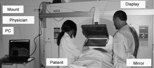
The concept of 2D tomographic image overlay is shown in . A flat-panel display and semi-transparent mirror are mounted on the gantry of a CT scanner. We acquire an image slice, flip it horizontally, adjust its magnification, and then render it on the display. The scanner, display, and mirror are aligned so that the reflection of the CT image that appears in the mirror coincides with the patient's body, as shown in . The system creates the impression that the CT image is floating inside the body in the correct pose and magnification, thereby giving the physician an X-ray tomographic vision. This technique can also be characterized as an in situ visualization tool, where the medical image is rendered in the context of the surgery, spatially registered with the patient's anatomy. In most needle placement procedures, after selecting the entry point, motion of the needle with three degrees of freedom (DOF) has to be controlled. In this system, the physician uses the overlay image to control the in-plane insertion angle (first DOF) while holding the needle in the plane of the overlay image that we mark with a laser light (second DOF). The insertion depth (third DOF) is controlled with a ruler and virtual depth gauge drawn on the overlay image. The physician may also apply stripes or sterile markers to indicate the desired depth or a clamp to prevent overdriving the needle. The use of 2D image overlay does not alter the traditional unassisted procedure to which physicians are accustomed, but it increases the amount of visual information in the field of action.
Figure 1. Concept of the 2D image overlay: a flat display and semi-transparent mirror are co-aligned with the CT scanner to produce an image to guide interventions.
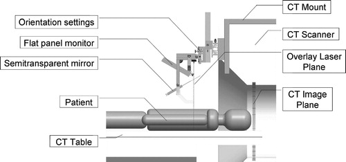
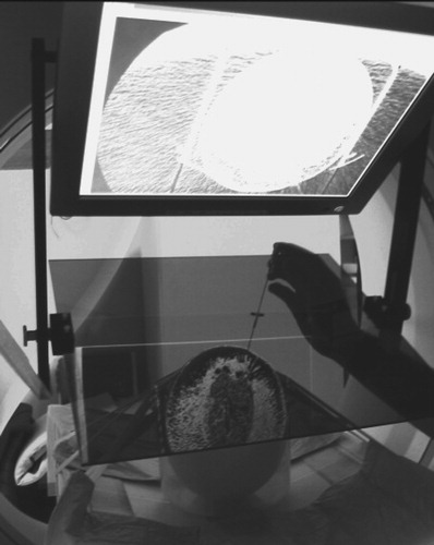
Figure 2. Physician's perspective: the overlay image in the mirror appears to be floating inside the subject while the physician manipulates the needle behind the mirror. (Phantom experiment on a honeydew melon.)
The advantages of 2D image overlay are significant in comparison with other virtual reality augmentation methods reviewed in the previous section. The most appealing aspect of the 2D image overlay is that the physician can execute the procedure without turning attention away from the patient while executing the same motions and actions as in conventional freehand procedures. In addition, multiple participants can share the same view. The 2D image overlay provides an optically stable image without auxiliary tracking instrumentation and requires only a simple pre-operative alignment. The system is simple and inexpensive; the replication of the system costs approximately US$3500. A major benefit of the 2D image overlay is making pre-insertion CT images available for intra-procedural guidance without exposing the patient and physician to additional radiation.
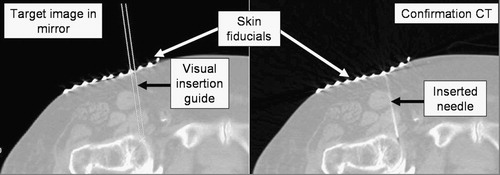
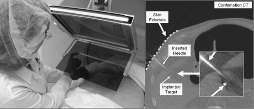
It is important to compose a workflow that retains all major aspects of the unassisted traditional freehand technique while augmenting the procedure with an extra flux of visual information. At any time during the procedure, the physician must be able to move the image overlay device away from the field and resume the procedure in the traditional manner without interruption. We position the subject under the overlay on the table as customary in the given procedure with the appropriate immobilization and fixation. We acquire a small slab of CT slices with a slice thickness appropriate for the given clinical application. We select the preferred slice of insertion and place an IZI CT biopsy strip external fiducial (IZI Corporation, Baltimore, MD) on the skin, as seen in . The IZI strip is composed of equally spaced parallel line markers. The IZI strip is placed on the patient so that the rods intersect with the plane of imaging, thereby leaving a dense pattern of equally spaced bright dots in the CT image. We use the IZI strip to relate the entry point picked in the CT to the actual patient. The accuracy of this co-registration is determined by the slice thickness, the width of the laser light, and the density of the rods in the IZI strip. The physician uses eyesight to place the needle in the middle of the laser line and halfway between two rods, which typically yields an accuracy of ≈ 1 mm. Next, a single CT slice is acquired and transferred in DICOM format to the planning and control software implemented on a stand-alone computer (Dell laptop, MS Windows-XP). The laptop concurrently drives the flat panel display of the overlay device, for which the image is flipped horizontally so that the mirror will flip the image back to normal lateral polarity. We keep the insertion planning software simple and intuitive to speed up the process. The CT window/level parameters can be interactively adjusted. The entry and target points are picked in the CT image by two mouse-clicks. The computer marks the target and entry points, draws a visual guide along the trajectory of insertion, and marks the depth of insertion. The CT table is translated out by the known offset between the image slice and the overlay plane. The physician holds the needle at the entry point behind the mirror and adjusts the angle to match the virtual needle guide while holding the needle in the plane of the laser, as shown in . This posture allows the physician to insert the needle with a single stroke along the marked trajectory. After the needle is inserted, a confirmation image is acquired.
Figure 3. IZI biopsy strip fiducial as seen both on the subject and in the overlay image (abdominal phantom experiment).
One could argue that the IZI strip is redundant in the image overlay system, but it is precisely this redundancy that provides us with extra layers of safety. The IZI strip has been used in our traditional CT-guided needle insertion protocol. When using the image overlay system, we must have the ability to revert to the traditional workflow in case of emergency or hazard. Therefore, using the IZI strip is mandatory. Furthermore, the IZI strip is visible on the patient and in the overlay image, the coincidence between the corresponding marks indicating correct alignment between the image and the patient. This feature is particularly important for quality assurance, especially in applications when the target anatomy is prone to motion because of respiration or mechanical pressure exerted by the needle. Skin fiducials are most useful in gating the needle insertion to the respiratory cycle, which we explain later in the experimental section. Correct alignment of the skin markers is necessary (but not sufficient by itself) for correct anatomical targeting. Although skin markers are not perfect surrogates of deep target motion, in many applications they can reasonably infer target position. Hence, the IZI strip provides increased safety in the image overlay system. The use of the IZI strip also eliminates the effects of optical parallax during needle insertion, because we identify the needle insertion point on the patient's skin by the IZI strip, rather than by the overlay image. Once the needle tip is committed, we keep the needle parallel to the virtual needle guide drawn on the overlay image. Although parallax can make the needle appear to be shifted away from the virtual guide, we know that this is just an optical illusion, because the needle is firmly lodged in its entry point. We simply disregard the parallax shift and concentrate on keeping the needle parallel to the virtual needle guide.
Image overlay embodiments
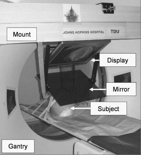
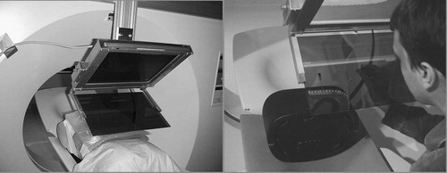
The prototype shown in renders the overlay image in the scan plane of the machine (GE Medical Systems, Waukesha, WI, USA). The mount is made of wooden beams, allowing for great prototyping flexibility at low cost. The position of this mount is not well repeatable, so a 7-DOF passive arm is used to adjust the overlay image with the scanner each time the system is remounted. With this embodiment, we gain rapid imaging confirmation without moving the patient. In contrast, there is often insufficient access to the site of action inside the gantry and the subject on the couch cannot be moved without dismounting the overlay device first. This problem can be alleviated by translating the table out of the gantry and creating the overlay image in a more convenient position.
Figure 4. Image overlay system that creates the floating image in the scan plane of the CT gantry. (A close up of this experiment is shown in .)
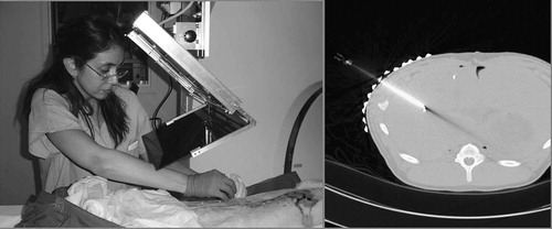
The system shown in creates the overlay image in the outer axial laser plane of the CT scanner. (We used a Somatom-4 scanner from Siemens, Erlangen, Germany). This arrangement provides ample room for the patient and multiple physicians, but it also requires translating the CT table between imaging and action. (In contemporary practice, usually no time is lost with couch translation, because the operator moves the couch while the physician is entering the room.) The patient is fixated with foam wedges and wide velcro straps, so target offset due to couch translation usually stays within the safety limits. The mount is built from extruded aluminum, which offers structural integrity and easy machining and is lightweight and aesthetically pleasing. Two average-size technicians can mount the basic hardware in a few minutes. The repeatability of the mounting, with respect to the gantry's laser planes, is more accurate than the width of the laser (≈1.5 mm), as tested in 10 experiments. As the mounting is very reliable, the passive arm holding the rigid display/mirror unit has only three adjustable joints, in contrast to the 7-DOF arm in the first prototype. The weights of the display/mirror unit and the mount are 4.0 and 20.5 kg, respectively. This is an insignificant extra weight on the gantry and creates virtually no torque on its joints. We also verified that the overlay device did not interfere with the laser lights of the scanner. The mirror is a 4-mm light-brown acrylic sheet. It was selected for its low cost and ease of machining, though plastic generally does not produce a crisp reflection and the somewhat faint display (also of no particular brand name) further amplified this deficiency. The entire optical unit is built as a single rigid unit which is not altered or adjusted during the lifetime of the device. The angle between the display and mirror is 60°, which has been universally applicable in all procedures tried. The sizes of the display and mirror need to match. A single but large display–mirror unit would not cover all potential targets, and such a large unit would intrude on the physician's workspace and collide with the patient when the gantry is tilted forward. At the same time, the field of view needs to be large enough to capture the length of insertion. Considering all constraints, a 15-inch LCD display and mirror are used. The display unit can move left–right (according to the site of insertion) and up–down (according to the patient's size). Although this system functions excellently in practice, some shortcomings are apparent during setup and calibration, when it is rather cumbersome to adjust the optical unit to the laser plane. We depend highly on the reproducibility of the mounting, rather than on easy adjustment of the optical unit.
Figure 5. Image overlay system that renders the image in the outer transverse laser plane of the CT scanner. The patient is conveniently accessible for multiple physicians who share the same view.
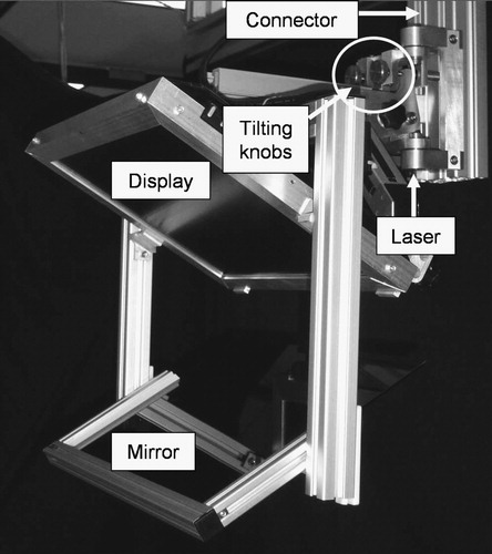
The system shown in produces the reflection image in an arbitrary transverse plane of the CT scanner (Somatom-4, Siemens, Erlangen, Germany). It carries its own laser light (60° cone angle, 4 mW, 670 nm red laser, made by Coherent, Auburn, CA, USA), which is precisely aligned with the mirror and display at 60° and 120°, respectively. The optical unit (including the display, mirror, and laser) is built as one rigid body. Instead of acrylic, we apply a tinted glass mirror that gives a crisper image than plastic. The overlay device is mounted on the same extruded aluminum structure, but with a different mounting connector. Although this connector provides the same gross in-plane motion, it has two knobs that provide precise 2-DOF out-of-plane rotation for the display unit during pre-operative setup. The frame of the display unit is robust and precisely machined. The display unit and mount connector together weigh ≈ 12 kg, which is more than in the other two systems, but still an insignificant weight on the gantry. This system represents a major improvement when compared with the previous two embodiments in that the display unit is free from geometrical constraints imposed by the scanner, which in turn allows for greater freedom in mechanical design and easier calibration. The fringe benefit of these improvements will be better quality control when the system is used clinically. From the physician's perspective, this embodiment is functionally equivalent to the one shown in .
Figure 6. Image overlay system that shows the floating image in an arbitrary transverse plane. Decoupled knobs are used to rotate the display parallel to the scanner's imaging plane.
Calibration
Iterative calibration
The image overlay system must be calibrated to the scanner every time it is re-mounted. One approach is to calibrate the system iteratively in three major steps: (1) Determine the scale factor between the CT and overlay images. (2) Bring the overlay device to a pose where the plane of the overlay image is parallel to the imaging plane of the scanner. (3) Determine the in-plane transformation between the overlay image and the physical object in the mirror. (The offset between the scan plane and the overlay plane is known a priori or can be read from the table encoder.)
The overlay image must appear in the correct size in the mirror, but there is variable linear scaling between the CT image and displayed image. The pixel size of the display is constant and either is known from the manufacturer's specification or its measurement is trivial. The pixel size of the CT image is calculated as the ratio between the field of view (in mm) and image size (in pixels): both are known from the scanning protocol that is encoded in the header of the DICOM image. The scale factor is calculated as the ratio between CT and display pixel size.
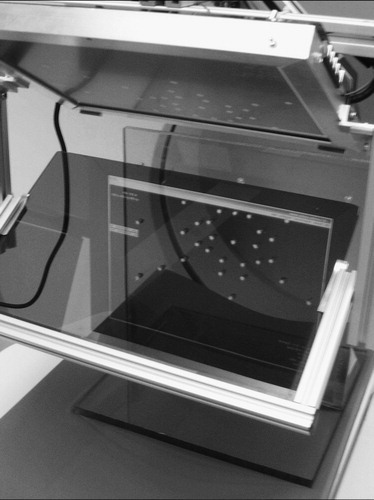
We fabricated a calibration phantom containing a base board and a perpendicular fiducial board, the latter with an asymmetric set of aluminum pegs 5 mm in diameter and 10 mm long, as shown in . The boards are made of 10-mm-thick clear, radiolucent acrylic. We ensure parallelism between the CT image plane and the overlay image plane through the following sequence: We manually adjust the calibration phantom on the CT table until the gantry's inner laser plane (which is of good quality) sweeps the front face of the fiducial board; secure the board to the table; translate the table; align the phantom under the overlay device; render an arbitrary test image; and adjust the mount adapter until the overlay image appears on the front face of the fiducial board. Although we use eyesight in judging the correctness of plane alignment, the board is sufficiently large (40 cm) and the laser sufficiently thin (1.5 mm) to allow for accurate alignment.
Figure 7. Calibration phantom made of perpendicular acrylic boards with aluminum pegs. After calibration, the overlaid CT slice of the phantom is in perfect overlap with the physical object.
Next, we determine the 3-DOF in-plane rigid body transformation (2D translation and 1D rotation) between the scaled CT and overlay images in the following sequence: We acquire a CT image of the fiducial board; auto-segment the marks of the aluminum pegs in the CT image; lean over the mirror; pick the points where the actual pegs appear through the mirror; adjust the in-plane rotation and translation of the image until each aluminum peg coincides with its mark in the image; apply the resulting 3-DOF transformation on the CT image; and redisplay the image on the overlay. In essence, the registration is based on rigid body correspondence between two sets of points, an idea that has been widely used in disciplines from general robotics to computer-assisted surgery. Because calibration is a critically important component of the system, we must discuss the particulars of this process in detail. In our case, there are two possible approaches to point-based rigid body registration: (1) Optimize the registration for minimum error in one step after collecting all corresponding pairs of points. (2) Progress gradually in an iterative cycle, picking only one corresponding pair and recovering the translation or rotation alternately in each iteration until correct registration is achieved. From our perspective, the one-step method is less practical, because using all points is usually superfluous, but using less than all of them is a gamble: if the registration needs only a tiny adjustment at the end, we still must repeat the entire registration process from the beginning. We must add, however, that the iterative registration relies on accurate point pairs, and the translation estimation, in particular, may be sensitive to noise (i.e., human error) and is less robust than least-squares minimization over all pairs. A severe outlier may throw off the registration, which the operator must detect visually and compensate for by either undoing the outlier or adding more registration points. We chose the iterative rigid body registration approach for its inherent practicality and convenience. The flow of the iterative registration is explained next. We iterate in the following cycle until the exit criteria are met:
Choose a point in the CT image and then choose the corresponding point as seen through the mirror. (To start, pick a point near the center of the image.)
Calculate the required in-plane translation p to align the selected point.
Translate the CT image.
Display the adjusted image.
Choose another point in the CT image and then choose the corresponding point as seen through the mirror.
Calculate the angle θ representing the angular misalignment in the axis normal to the imaging plane. The center of rotation is the point selected previously for translation.
Rotate the CT image by the calculated amount about the chosen center of rotation, in-plane.
Display the adjusted image.
Make a quick visual assessment of the registration. Continue the cycle if necessary, otherwise exit. (Note that one could also apply quantitative exit criteria for the amount of translation and rotation, but we found the quick visual check to be sufficient for our clinical applications.)
It is worth noting that the translation component is rather unpredictable, because it depends on where the overlay image is created within the transverse plane defined by a great number of variables, but the rotation is always close to identity.
We also analyzed the combined effects of human and optical errors on synthetic data, with the objective of determinating the optimal number, distribution, and selection order of registration points, given the thickness and diffraction coefficient of the mirror. We artificially misaligned the two sets of points (i.e., the pegs and their respective image coordinates) by applying a known transformation on each pair and adding noise to each data point. Human error was simulated by adding a random value (2 pixels) to the position of the point to be registered. Parallax error from the mirror may induce a significantly large error. At d = 4 mm thickness and α = 30° view angle, the parallax error (x) is ≈ 1.28 mm, the effect of which, fortunately, can be substantially reduced by altering the view points during the calibration process. We also concluded that iterative re-registration was more favorable than collecting all registration points first and then calculating a single global registration. This observation was true across the range of practically relevant amplitudes and distributions of noise and number of registration points. We found the following to be the best strategy: (1) Pick a peg near the area of interest in the vicinity of the expected target and entry and let the computer calculate the translation and re-adjust the overlay image. (2) Pick a peg far out from the previous one and let the computer calculate the rotation and re-adjust the overlay image. (3) Pick a new peg again relatively close to the area of interest to adjust translation. (4) Pick another peg to adjust rotation, far out and at 90° from the previous one. (5) Repeat the pair-wise process until sufficient registration is observed between the phantom and its CT image. It is particularly important to compensate for the parallax error by altering the viewpoint. The simulated registration error, using four pairs of registration points and assuming a 2-pixel human error, was 1.23 mm (STD = 0.31) at α = 30° and 0.74 mm (STD = 0.21) at the perpendicular view (α = 0°). This performance appears to be adequate for most CT-guided needle placement procedures. It is to be noted that the locations of aluminum pegs in the calibration phantom do not need to be known a priori, so in this respect, the phantom does not need to be precisely fabricated. In contrast, the overall process requires manual labor, and the process of picking the registration points is subject to optical parallax and other human errors. Another nuisance is that the laptop computer and mouse need to be next to the overlay device, which is prone to obstruct normal traffic in the room. Despite involving human interaction and perception, the iterative calibration method allowed for excellent accuracy, consistency, and robustness in the phantom and cadaver experiments, as described in the next section.
Stereotactic calibration
We have also developed a stereotactic calibration approach to reduce the role of human judgment and parallax, by applying a rigid stereotactic adapter shown in . The calibration adapter attaches reproducibly to the overlay device. It is a rigid structure that contains eight radio-opaque aluminum fiducial rods, each 6.0 mm in diameter. The CT image cuts across the rods, which leave bright white marks in the CT slice. Assuming that the relative poses of the rods are known and at least three of the rods are not parallel, one can discern the pose of a CT image relative to the rods. In earlier works, we have introduced miniaturized fiducial frames for registration of surgical robots to CT Citation[18], Citation[19]. We have perfected this method to support fiducial structures that are not composed of precisely machined Z-shaped motifs, and whose image data are incomplete Citation[20]. Given the fact that the imaging protocol is well controlled and the quality of image data is thus predictable, we employed a simplified version of the method described by Lee et al. Citation[20]. In essence, here we apply a linear numerical optimization method. The following are assumed to be known a priori: (1) the equation of each fiducial line in the coordinate frame of the stereotactic adapter, (2) the location of each mark in the CT coordinates, and (3) the 3D magnification between the CT frame and adapter frame. We formulate the task to find the 6-DOF rigid transformation between the CT plane and fiducial lines which produces the best fit between the marks and the lines by arriving at the absolute minimum of a properly chosen cost function. Arguably, the most straightforward and comprehensible metric is the sum square of the Euclidean distance of each point from the corresponding line. The selection of the cost function reduces the problem to a least square numerical optimization that is straightforward to solve. The question concerns the robustness of this approach, i.e., whether we really obtain the best solution and whether the optimization does not get stuck in some local minima along its way toward the absolute minimum. Although there is never a guarantee, in this particular case we are safe for several reasons. (1) There is very little uncertainty in the input data. The equations of the fiducial are based on precise measurements, as we describe later in this section. The fiducial rods produce sharp and well-separated marks in CT. The rods are segmented with a region-growing algorithm Citation[21] that uses the standard ‘textbook’ region-growing algorithm with a stopping criterion that combines local and global differences between gray values of voxels, as well as a technique to add geometrical constraints based on the a priori knowledge about the structure being segmented. The position of the rod was determined as the center of gravity of the segmented region. (2) The stereotactic adapter is large, the rods are well separated, and the cross-rods are slanted at a 45° angle to produce the largest possible gradient in the distance function. (3) The initial guess for the optimizer is nearly perfect, because the initial misalignment between the CT image and the stereotactic adapter is very small. (4) The correspondences between the CT marks and fiducial rods are unmistakably known. (5) All rods are seen in the CT image, thus we work with highly redundant data which reduce registration error.
Figure 8. Stereotactic calibration adapter mounted on the image overlay device (left) and CT image of the adapter (right). The CT image shows sharp marks from the rods that can be conveniently segmented.
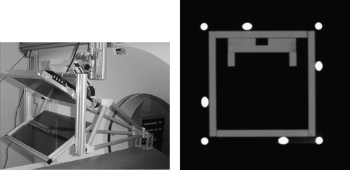
First, we must measure the relative pose of the fiducial rods with respect to the overlay display, as depicted in . We use an Optotrak tracker and a calibrated pointer (Northern Digital Inc., Waterloo, ON, Canada). With an accuracy of up to 0.1 mm and resolution of 0.01 mm, the Optotrak tracker stands out as the ‘gold standard’ of precise position measurement in surgical navigation systems. We attach a set of Optotrak markers to the overlay device to gain a static frame of reference denoted FS. We render a set of points on the LCD screen and by touching these points with the pointer we determine the display frame denoted FD. It is then trivial to derive the frame transformation (FDS) which leads from the static frame (FS) to the display frame (FD). Again, note that the FSD transformation matrix derives directly from Optotrak measurements, in which the rotation and translation are either wrong or correct, but usually go together and are very reliable. (Prior to the measurements, we also ascertained that there had been no systematic error in the readings from the pointer and tracker.)
Figure 9. Frame transformations in stereotactic calibration. FSD and FAS are measured with the Optotrak tracker in the laboratory while FCA is determined inside the scanner.
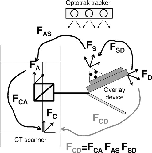
Small dimples are precisely machined at both ends of the fiducial rods in which we pivot the Optotrak pointer. (We use pivoting motion to collect a large number of readings that we average out to obtain the position of the tool tip.) Two endpoints fully define the spatial location of a rod, and the rigid set of rods defines the adapter frame (FA). It is trivial to derive the frame transformation (FAS) which leads from the adapter frame (FA) to the static frame (FS). Regarding possible errors in FAS, the following can be said. We first evaluated the reproducibility of the stereotactic adapter's pose by remounting it 17 times on the overlay device. In measuring the position of the adapter with the Optotrak tracker, the average error was found to be 0.16 mm (STD = 0.12), which corresponds to ≈ 25 percent of a CT pixel. Importantly, this result also infers that the transformation from static frame to adapter frame (FAS) was very accurately measured.
In the CT room, we attach the stereotactic adapter to the overlay device and acquire a CT slice. (Note that only one slice can be collected, because the adapter is stationary on the gantry.) We carefully segment the center of each rod and, using the aforementioned modified method of Lee et al. Citation[20], we derive the frame transformation (FCA), which leads from the adapter frame (FA) to the CT frame (FC). We have analyzed this method through a series of articles, as reviewed in reference 20, and have high confidence in the results.
Finally, the concatenation of the aforementioned three frame transformations provides the frame transformation that leads from the CT frame to the display frame, expressed as FCD = FCA*FAS*FSD. We can break down FCD to a series of homogeneous components, which we either incorporate in the display software or compensate for in the treatment room, as described in the following.
Three-DOF scaling between the CT frame and overlay display frame, which we incorporate in the display software. This is based on a priori known pixel sizes and is highly accurate.
One-DOF translation in the craniocaudal direction, which we provide by encoded table motion. The translation component of FDC is not necessary to compute, because we simply read it out from the table encoder translation between the CT image plane and overlay image planes; this value is always trustworthy.
In-plane 2-DOF translation and 1-DOF rotation, which we incorporate in the display software. To evaluate the accuracy in predicting these in-plane transformations, we acquired seven calibration images in different and purposely misaligned poses for an off-line analysis. We calculated the transformation between the adapter frame and the CT frame (FCA) and then intersected the reconstructed stereotactic adapter with the CT image. We determined the dislocation between the predicted and actual marks of the fiducial rods in terms of image pixels. We found that all fiducial rods were projected within a 2-pixel (0.5 mm) in-plane error, which also inferred a maximum 0.7 mm out-of-plane craniocaudal translation error for the worst reconstructed rod. (The actual error, owing to the averaging over a highly redundant structure, is always less.)
Out-of-plane 2-DOF rotation, which we eliminate by turning the two calibrated tilting knobs on the mount connector. Then, we take a confirmation image to verify that the out-of-plane rotation component has disappeared from FDC (i.e., it is close to identity) and we repeat the adjustment if necessary. It is important to note that the axes of the aforementioned 2-DOF out-of-plane rotation are implemented close to the overlay image, so that the rotational registration error does not get magnified by the usually large distance (≈60 cm) between the scan plane and the overlay plane. Nevertheless, we mitigated the effects of rotational error by using a large stereotactic adapter (100 × 100 mm2 cross-section) and by scanning it with small CT pixel size. The accuracy in predicting the rotational component of FDC was also examined. Using a digital inclinometer as ground truth, we placed the overlay device in a perfect vertical position and acquired a CT image of the stereotactic adapter. This CT image served as the canonical plane of reference. Then, on the basis of the gear ratio of the knobs, we tilted the device (with the stereotactic adapter mounted on it) by known angles. We verified the angle with the digital inclinometer and found subdegree agreement between the knobs and the inclinometer. In each of these positions, we acquired a CT image of the stereotactic adapter and let the calibration software extract the out-of plane rotation angle with respect to the canonical reference plane. We found subdegree agreement between the inclinometer and the rotation angle predicted by FDC. This strong agreement does not surprise us, because stereotactic Z-frame adapters have an exquisitely excellent track record in spatial registration in neurosurgery and radiotherapy.
Considering all the factors, these preliminary data suggest that this stereotactic calibration method can replace the earlier described iterative calibration method in our forthcoming clinical-grade system.
Experiments and results
Phantom experiments
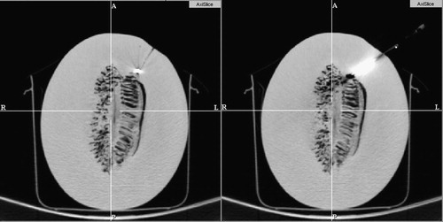
First, we tested the proof-of-concept prototype in the setup shown in and . The overlay image was rendered in the plane of imaging inside the gantry. We implanted a honeydew melon with multiple 1.5-mm-diameter metal pellets serving as targets. The melon simulated the locations of head, neck, and intra-cranial targets. We used a standard brain-imaging protocol with 1-mm slice thickness and standard 20-gauge diamond-head stainless steel needles. We applied a spring-loaded clamp to gauge the depth of insertion. We assessed the accuracy in post-insertion CT, with 1-mm slice thickness. Tested in three interventions, the needle tip approached the implanted metal ball target within 2 mm in every attempt. The error was measured from the border of the target at standard nominal bone window/level. A pair of those targeting and confirmation CT images is shown in . As mounting the overlay device inside the scanner presents major problems by limiting access to the subject, in all subsequent trials we used the system shown in , where the overlay image was created in the outer laser plane of the gantry.
Figure 10. Target and confirmation image in phantom experiment with a honeydew melon. A 1.5-mm metal target was implanted in the melon (left), which was then subsequently hit by the 20 G needle (right).
Next, we tested the image overlay system on a male upper body phantom, as seen in (left). We built this model by attaching tissue-equivalent bolus material (Harpell Associates Inc., Oakville, ON, Canada) of 3 cm thickness on the back of a plastic male torso. We placed 1.5-mm-diameter metal balls in the bolus at various depths. This mannequin served as a male upper body in prone position, with a hard fat/muscle layer with implanted targets around the back, spine, and shoulder. An experienced interventionalist evaluated the accuracy and ergonomics of the system in four targeted insertions of an 18-gauge diamond-tip needle. Post-insertion CT with 1-mm slice thickness showed that the needle approached the implanted target within 2 mm in every attempt. The error was measured from the border of the target at standard nominal bone window/level. There was no interference in the workspace and all targets were conveniently accessible. A similar trial was also conducted on a commercial interventional phantom (CIRS, Norfolk, VA, USA) shown in (right), with the same positive outcome.
Figure 11. Phantom experiments on a male mannequin (left) and a tissue-equivalent commercial abdominal intervention phantom (right).
Cadaver experiments on skeletal targets
Having tried the system on mechanical phantoms, we progressed to experiments with true biological tissues of human cadavers. The primary objective was to demonstrate the ability of clinically successful needle placement to various anatomical targets in several potential clinical applications in the skeletal system. These pilot studies were reported in reference 17 and are summarized as follows. We performed 12 needle insertion trials in various skeletal targets and achieved clinically acceptable placement accuracy on the first insertion attempt in all trials. In all cases, 22-gauge beveled needles were used and the accuracy of needle placement was assessed in post-insertion CT. In both targeting and verification, we followed the standard imaging protocol that is usually applied clinically with the traditional freehand unassisted technique. The slice thickness was between 1.0 and 3.0 mm. The following applications were explored:
Joint arthrography, which is a method for the detection of ligamentous, tendon, and fibrocartilage injuries in joints. The procedure involves the injection of MRI contrast agent into the injured joint under radiographic imaging. The requirement was to deliver the needle into the joint space of the shoulder and hip, which we achieved in the experiment. An example of hip arthrography insertion is shown in .
Bone biopsy, which often begins with the insertion of a thin pilot needle, followed by a large coring needle. The required accuracy in placing the pilot needle was ≈ 3 mm, which we achieved in the experiment.
Spinal nerve blocks and facet joint injections, which are demanding procedures, primarily because of the high volume of cases. The required clinical accuracy was ≈ 2.0 mm, which we achieved in the experiment.
Figure 12. Target image (left) and confirmation CT image (right) in a hip arthrography.
Cadaver experiments on liver targets
Having established the basic feasibility of the system on skeletal targets, we continued our progress toward the greater challenge of percutanenous abdominal interventions. Percutaneous abdominal insertions are exceedingly difficult owing to constrained access, excessive target motion, tissue deformation, and needle deflection. Target displacement is typically caused by respiration and mechanical interaction between the needle and living tissues. We compartmentalized these problems by using human cadavers first and then fresh ventilated pig cadavers. Our initial abdominal target was the liver, which is technically perhaps the most challenging organ system in the abdomen.
Human cadaver study
We placed a large (≈220 lb) male cadaver in supine pose under the image overlay, as seen in (left). We applied 18-gauge beveled needles on pre-implanted 1.5-mm metal pellets as targets. One particular challenge was to achieve lateral access, which we managed by translating the overlay device sideways on the gantry mount. We performed insertions on three different targets, each along two different access paths. We applied straight gantry (i.e., transverse access plane) and 18-gauge needle. We recorded a rather variable success rate in that only once were we able to hit the target on the first attempt and one target remained inaccessible (we did not find clinically feasible access to it) because of interferences with the rib cage. This was not quite unexpected, as we applied straight gantry throughout the study. Altogether, the success rate was markedly lower than we had earlier obtained with skeletal targets, where we always managed to place the needle within the allotted margin of error on the first attempt. However, when clear access opened to the target, we achieved generally good accuracy. A successful case is shown in (right), where the needle approached the implanted target with sufficient accuracy while remaining completely in the plane of the overlay image. Occasionally, we observed significant bending of the 18-gauge needle in the stiffened cadaver. This effect is expected to be less pronounced in vivo with actual biopsy needles or radio frequency ablators. At the same time, the human cadaver did not reflect realistic organ mobility and it lacked respiratory motion. Although this experiment was limited to yield strong statistical data, the experiment was highly suggestive for a more detailed study that we plan to undertake in the future.
Figure 13. Liver insertion in a human cadaver (left) and confirmation CT image (right).
Ventilated pig cadaver study
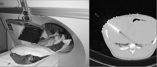
In order to simulate a more realistic in vivo environment, we performed needle placement into the liver of ventilated fresh pig cadavers, as seen in (left). The average weight of the pigs was ≈ 25 kg. The cadavers were used within 2 h of being sacrificed in an unrelated trial. (In our institution, experiments can be performed on otherwise healthy cadaveric animals without an approved and monitored animal care protocol, which significantly reduces logistical complexity. The only drawback was that our schedule had to be synchronized to the other trials, which is surmountable in an institution as large as Johns Hopkins.) We kept the cadavers on the respirator and under warming blankets to delay rigor mortis, which otherwise would have biased the outcome by reducing tissue deformation and mobility. The targets were previously implanted in unrelated surgical procedures that left the area of interest intact. Stainless steel staples, typically used in laparoscopic abdominal surgery, served as targets. Image acquisition and needle insertion were performed under prolonged breath-hold that was simulated by halting the respirator. Pig skin was much harder to penetrate than human skin, which we performed by making a small (≈2 mm) incision at the entry point. Otherwise, we used the same workflow as earlier with the skeletal targets in human cadavers.
Figure 14. Needle insertion in the liver of a ventilated pig cadaver with straight gantry (left) and a confirmation CT image (right).
First, we experimented with straight gantry, as seen in (left). The targets, surgical staples in this case, were implanted at variable depth. A particularly challenging target, shown in (right), was placed at ≈ 55 mm depth. In this case, we chose an access route at an angle of approximately 45° between two ribs. Generally, this kind of right lateral insertion was extremely difficult for our surgeon to perform because he was right-handed, but had to use the weaker left hand to complete the insertion within the allotted time of one breath-hold. It was even more difficult to perform the insertions in a purely horizontal lateral path when the surgeon had to press on the needle very hard to puncture the oblique and/or dorsal muscles while keeping it aligned with the laser and virtual needle guide at the same time. In the example shown in (left), the needle stayed in the transverse plane and approached to ≈ 2.5 mm from the implanted target.
Similar to our previous experience on human cadavers, using straight gantry, some targets were only accessible through clinically infeasible paths because of interferences with the rib cage. To obtain better access to those hidden targets, we experimented with tilted gantry as shown in (left). We modified the protocol to determine the optimal tilting angle by first acquiring a lateral scout image of the subject and then measuring gross orientation of ribs, and finally tilting the gantry to have clear paths to the targets between the ribs. With tilted gantry, all targets were accessible in all desirable directions. A successful case is shown in (right), where the needle, although it went slightly out of plane, still approached to ≈ 2.5 mm from the center of the metal target. Generally, the maximum gantry angle was limited because of potential collision of the overlay device, table, gantry, and patient. The maximum gantry tilting was ≈ 30° in the pig experiments and is expected to be somewhat less for human patients because of their larger size. With tilted gantry, the torque created by the weight of the overlay display could also cause out-of-plane flexure, but we did not notice any deflection owing to the excellent stability of the extruded aluminum mount and the sturdy connector between the display and the mount.
Figure 15. Needle insertion in the liver of a ventilated pig cadaver with tilted gantry (left) and a confirmation CT image (right).
Altogether, we performed a total of 22 needle insertions in ventilated pigs. All insertions were performed by the same surgical fellow. The experiments were concluded before rigor mortis set in, so the cadavers were considered to be accurate models of anesthetized in vivo subjects. We recorded an average of 6.4 mm position error (STD = 1.8), 0.3 mm insertion depth error (STD = 2.0), and 2.1° directional error (STD = 3.1), as discussed in . The error was measured at the first trial without re-insertion of the needle. The error was measured from the center of the staple, as it was identified in the CT volume. The table combines experiments with both straight and tilted gantries, as for the pigs we did not consider whether the access path was clinically safe, because we were only interested in assessing how the image overlay system helped the act of needle placement. We noticed gradually improving performance from the surgeon, who tended to produce more favorable accuracy after a few cycles, though noticeable variability remained in the data, as seen in . In some cases, significant dislocation was measured between the pre- and post-insertion target positions. At the same time, however, needle placement error did not appear to be markedly higher on dislocated targets, giving rise to the hope that target dislocation may have been mitigated by the image overlay system. The proof of this conjecture, however, requires a larger number of experiments carried out under a more rigorous protocol.
Table 1. Summary statistics for liver access in ventilated pigs. The total number of experiments performed was 22. The table does not differentiate between cases done with straight and tilted gantries.
Table 2. Results of liver access in ventilated pigs. The table does not differentiate between cases done with straight and tilted gantries.
Discussion
The first prototype was mounted in the inner laser plane of the scanner, where the physician's workspace was often restricted and several targets were not accessible. Therefore, the decision of the participating physicians was to produce the overlay image outside the scanner, even though it required translation of the CT table between imaging and needle insertion. Although respiration and involuntary motion could not be simulated in the passive phantoms and cadavers, the IZI biopsy strip fiducials placed on the ventilated pigs provided robust real-time indication of any patient motion, in which case the insertion was halted until the body was correctly re-aligned under the overlay image. The IZI fiducials were also useful for re-registration of the subject without re-imaging using the iterative registration technique. It is worth re-emphasizing that the IZI markers eliminate the effects of parallax, because the entry point on the patient's skin is defined by the IZI markers rather than by the optical image. After the needle tip is committed, we only need to keep the needle parallel to the virtual needle guide in the overlay image. Parallax makes the needle look as if it drifted away from the virtual guide, but we know that this is an optical illusion, because the needle tip is firmly lodged in the skin.
The stereotactic calibration method promises to be preferable over the iterative calibration method, because it appears to have a comparable accuracy in reducing the role of human judgment, manual intervention, and optical parallax.
Needle insertion was generally more accurate in phantoms than in human cadavers. First, the phantom tissue was softer and more homogeneous than human cadavers. Secondly, in phantoms, we used 18-gauge diamond-tip needles that barely deflected during insertion, whereas in the human cadavers, we used 22-gauge beveled needles, which had a stronger tendency to deflect in hard and inhomogeneous tissues. There are also several methods for mitigating deflection during freehand needle insertion, such as various combinations of jack-hammering, spinning, and simple pushing. As thin needles are generally used in superficial targets, off-axis dislocation of the needle tip usually remains within the clinical margin of error. One must also keep in mind that needle bending is not always unwanted. Beveled needles are often purposely deflected off bony structures to access narrow passages, for example, in facet joint and nerve block injections. Furthermore, needle bending does not necessarily cause the needle tip to land outside the clinical margin of error. However, pinpoint accuracy is always more desirable. Finally, we reiterate that the main goal of our project is not to ensure pinpoint accuracy, but to prevent clinically faulty needle insertions.
We have encountered several relatively minor problems in our experiments. Some physicians found it to be challenging to hold the needle in the transverse laser plane. Although presently this does not seem to be a clinically significant impediment, we are considering applying some form of mechanical constraint to aid the physician with holding the needle in plane. Changes in the room's illumination have caused difficulties. Although we draped the distal opening of the gantry, foreground light still often interfered with the overlay image. We plan to add a controlled light source on the frame and reduce occasional glare from the display frame by applying a dark satin coating. In the forthcoming clinical-grade system, safety glass needs to be used for the mirror, because common glass poses a safety hazard from scattering sharp chips in the event of breakage.
The workflow process and instrumentation have not been optimized to yield minimum procedure time and the ergonomics of the system still need to improve; these are subjects of current research. Connectivity with the scanner is of paramount significance. In the forthcoming clinical-grade system, we will retain the laptop computer, but circumvent the hospital's PACS and DICOM service to reduce delays and manual labor in pushing the images. We are also considering running the display software directly on the scanner's console as a stand-alone application. This level of integration, however, requires proprietary information from the scanner's vendor and would reduce portability. Nevertheless, this appears to be a most reasonable tradeoff between productivity and portability.
Overall, phantom and cadaver experiments on skeletal targets were successful in proving that the CT image overlay device allowed for clinically adequate and safe needle placement, and was effective in reducing the need for repeated insertion attempts and imaging. We achieved clinically acceptable placement accuracy on the first insertion attempt in 12 insertion trials. Skeletal targets, according to our experience, do not appear to dislocate by a clinically substantial amount during the needle placement procedure, especially if appropriate immobilization/fixation is used. For this purpose, Velcro bands, vacuum bags, and other devices are widely available. Upon completion of a limited number of in vivo animal trials, the system is expected to be cleared for initial human trials in bone biopsy, joint arthrography, nerve blocks, and facet joint injections.
Initial studies yielded promising technical accuracy and consistency in liver punctures. Tilted gantry appeared to be an effective tool, which should be thoroughly explored for the oblique-plane insertions that are often necessary in accessing liver targets. Our preliminary studies were not sufficiently controlled to produce statistically strong data, because we altered the workflow several times during the experiments. Nevertheless, initial results (6.4 mm average, STD = 1.8) are promising for liver biopsy and ablation, where the target size tends to be on the order of several centimeters. Liver and, more generally, abdominal targets require further procedure refinements and validation before initial human trials can be considered.
Acknowledgments
Funding was provided by NSF EEC-9731478, Siemens Corporate Research (Princeton, NJ, USA), and the Japanese Ministry of Education, Science, Sports and Culture Grant-in-Aid for Young Scientist Award #14702071.
We are grateful to Beatrice Mudge, R.T., for running the CT scanner in our experiments, to Herve Mathieu, Ph.D., for contributing the gantry mount, to Sheng Xu for data analysis, and to Frank Sauer, Ph.D., (Siemens Corporate Research) for scientific advice and financial arrangements.
Disclosure of financial interest
In this article, we make extensive reference to the ‘IZI biopsy strips’ manufactured by IZI Medical Products (Baltimore, MD, USA). Dr S. James Zinreich holds substantial but not controlling equity in this company.
References
- Cleary K, Nguyen C. State of the art in surgical robotics: clinical applications and technology challenges. Comput Aided Surg 2001; 6(6)312–328
- Taylor R H, Stoianovici D. Medical robotics in computer-integrated surgery. IEEE Trans Robotics Automation 2003; 19(5)765–781
- Birkfellner H, Figl W, Huber M, Watzinger K, Wanschitz F, Hummel F, Hanel J, Greimel R, Homolka W, Ewers P, et al. A head-mounted operating binocular for augmented reality visualization in medicine—design and initial evaluation. IEEE Trans Med Imaging 2002; 21(8)991–997
- Sauer F, Khamene A, Vogt S (2002) An augmented reality navigation system with a single-camera tracker: System design and needle biopsy phantom trial. Proceedings of 5th International Conference on Medical Image Computing and Computer-Assisted Intervention (MICCAI 2003), TokyoJapan, September, 2002, T Dohi, R Kikinis. Springer;, Berlin, 116–124, Lecture Notes in Computer Science 2489
- Edwards P J, King A P, Maurer C R, Jr, de Cunha D A, Hawkes D J, Hill D J, Gaston R P, Fenlon M R, Jusczyzck A, Strong AJ, et al. Design and evaluation of a system for microscope-assisted guided interventions (magi). IEEE Trans Med Imaging 2000; 19(11)1082–1093
- Frets E M, Strobe J W, Hatch K F, Roberts D W. A frameless stereotaxic operating microscope for neurosurgery. IEEE Trans Biomed Eng 1989; 36(6)608–617
- Iseki H, Masutani Y, Iwahara M, Tanikawa T, Muragaki Y, Taira T, Dohi T, Takakura K. Volumegraph (overlaid three-dimensional image-guided navigation) clinical application of augmented reality in neurosurgery. Stereotact Funct Neurosurg 1997; 68: 18–24
- Nakajima S, Nakamura K, Masamune K, Sakuma I, Dohi T. Three-dimensional medical imaging display with computer-generated integral photography. Comput Med Imaging Graphics 2001; 25: 235–241
- Blackwell M, Nikou C, DiGioia A M, Kanade T (1998) An image overlay system for medical data visualization. Proceedings of First International Conference on Medical Image Computing and Computer-assisted Intervention (MICCAI 1998), Cambridge, MA, October, 1998, W M Wells, A Colchester, S Delp. Springer;, Berlin, 232–240, Lecture Notes in Computer Science 1496
- DiGioia A M, Colgan B D, Koerbel N. Computer aided surgery. Cybersurgery: Advanced Technologies for Surgical Practice, R M Satava. Wiley;, New York 1998; 121–139
- Kockro R A, Serra L, Tseng-Tsai Y, Chan C, Yih-Yian S, Gim-Guan C, Lee E, Hoe L Y, Hern N, Nowinski W L. Planning and simulation of neurosurgery in a virtual reality environment. Neurosurgery 2000; 46(1)118–135
- Grimson W E.L, Ettinger G J, White S J, Lozano-Perez L, Wells W M, III, Kikinis R. An automatic registration method for frameless stereotaxy, image guided surgery, and enhanced reality visualization. IEEE Trans Med Imaging 1996; 15(2)129–139
- Masamune K, Fichtinger G, Deguet A, Matsuka D, Taylor R H (2002) An image overlay system with enhanced reality for percutaneous therapy performed inside CT scanner. Proceedings of 5th International Conference on Medical Image Computing and Computer-Assisted Intervention (MICCAI 2003), TokyoJapan, September, 2002, T Dohi, R Kikinis. Springer;, Berlin, 77–84, Lecture Notes in Computer Science 2489
- Masamune K, Masutani Y, Nakajima S, Sakuma I, Dohi T, Iseki H, Takakura K (2000) Three-dimensional slice image overlay system with accurate depth perception for surgery. Proceedings of 3rd International Conference on Medical Image Computing and Computer-Assisted Intervention (MICCAI 2000), Pittsburgh, PA, October, 2000, S L Delp, A M DiGioia, B Jaramaz. Springer;, Berlin, 395–402, Lecture Notes in Computer Science 1935
- Stetten G D, Chib V S (2001) Magnified real-time tomographic reflection. Proceedings of 4th International Conference on Medical Image Computing and Computer-Assisted Intervention (MICCAI 2001), UtrechtThe Netherlands, October, 2001, W Niessen, M Viergever. Springer;, Berlin, 683–690, Lecture Notes in Computer Science 2208
- Stetten G D, Chib V S. Overlaying ultrasonographic images on direct vision. J Ultrasound Med 2001; 20(3)235–240
- Fichtinger G, Deguet A, Masamune K, Fischer G, Balogh E, Mathieu H, Taylor R H, Zinreich S J, Fayad L M. Image overlay guidance for needle insertions in CT scanner. IEEE Trans Biomed Eng, 52(8), in press
- Susil R C, Anderson J H, Taylor R H (1999) A single image registration method for CT-guided interventions. Proceedings of 2nd International Conference on Medical Image Computing and Computer-Assisted Intervention (MICCAI 1999), CambridgeUK, September, 1999, C Taylor, A Colchester. Springer;, Berlin, 798–808, Lecture Notes in Computer Science 1679
- Masamune K, Fichtinger G, Patriciu A, Susil R C, Taylor R H, Kavoussi L R, Anderson J H, Sakuma I, Dohi T, Stoianovici D. System for robotically assisted percutaneous procedures with computed tomography guidance. Comput Aided Surg 2001; 6(6)370–383
- Lee S, Fichtinger G, Chirikjian G S. Novel algorithms for robust registration of fiducials in CT and MRI. J Med Phys 2002; 29(8)1881–1891
- Nyúl L G, Kanyó J, Máté E, Makay G, Balogh E, Fidrich M, Kuba A. Method for automatically segmenting the spinal cord and canal from 3D CT images. Joint Hungarian–Austrian Conference on Image Processing and Pattern Recognition (HACIPPR 2005—OAGM 2005/KPAF 2005), VeszprémHungary, May, 2005