Abstract
Objective: Recovering tissue depth and deformation during robotically assisted minimally invasive procedures is an important step towards motion compensation, stabilization and co-registration with preoperative data. This work demonstrates that eye gaze derived from binocular eye tracking can be effectively used to recover 3D motion and deformation of the soft tissue.
Methods: A binocular eye-tracking device was integrated into the stereoscopic surgical console. After calibration, the 3D fixation point of the participating subjects could be accurately resolved in real time. A CT-scanned phantom heart model was used to demonstrate the accuracy of gaze-contingent depth extraction and motion stabilization of the soft tissue. The dynamic response of the oculomotor system was assessed with the proposed framework by using autoregressive modeling techniques. In vivo data were also used to perform gaze-contingent decoupling of cardiac and respiratory motion.
Results: Depth reconstruction, deformation tracking, and motion stabilization of the soft tissue were possible with binocular eye tracking. The dynamic response of the oculomotor system was able to cope with frequencies likely to occur under most routine minimally invasive surgical operations.
Conclusion: The proposed framework presents a novel approach towards the tight integration of a human and a surgical robot where interaction in response to sensing is required to be under the control of the operating surgeon.
Introduction
The field of surgery is entering a phase of continuous improvement, driven by recent advances in surgical technology and the quest to minimize invasiveness and patient trauma during surgical procedures. Medical robotics and computer-assisted surgery are promising fields of study, which aim to augment the capabilities of surgeons by taking the best from both robots and humans. With robotically assisted minimally invasive surgery (MIS), dexterity is enhanced by microprocessor-controlled mechanical wrists, which permit motion scaling and reduction of gross hand movements. This technology also allows the performance of micro-scale tasks that would otherwise be impossible. Current robotic systems allow the surgeon to operate while seated at a console viewing a magnified stereo image of the surgical field. Hand and wrist maneuvers are then seamlessly translated into precise, real-time movements of the surgical instruments inside the patient. The continuing evolution of technology, including force feedback and virtual immobilization through real-time motion adaptation, will permit more complex procedures, such as beating heart surgery, to be carried out using a static frame of reference. The use of robotically assisted MIS also provides an ideal environment for integrating patient-specific pre-operative data for performing image guided surgery and active constraint control, all of which can be conducted without the need for the surgeon to remove his/her eyes from the operating field of view.
One of the major applications of robotically assisted MIS is the performance of totally endoscopic coronary artery bypass grafts (TECAB) on a beating heart. The main challenge of beating heart surgery is the destabilization introduced by cardiac and respiratory motion, which significantly affects precise tissue-instrument interaction and the execution of complex grafts. Despite the use of mechanical stabilization, the motion of the epicardial surface hinders delicate tasks such as small-vessel anastomosis Citation[1], which is compounded by the high viewing magnification factor used during the procedure. A number of 3D soft-tissue structural recovery techniques have been proposed for improved surgical guidance and motion compensation. These include the use of multi-view geometry based on novel computer vision techniques with or without the use of fiducial markers [2-5]. Despite the success achieved with these techniques, particularly for off-line processing, their potential clinical value with real-time in situ depth recovery is hindered by the morphological complexity and highly deformable nature of the soft tissue, coupled with the specularity and inter-reflections observed under common MIS conditions.
The purpose of this paper is to investigate the use of eye gaze for simplifying, as well as enhancing, robotic control in surgery. More specifically, we demonstrate that eye gaze derived from binocular eye tracking can be effectively used to recover 3D motion and deformation of the soft tissue during MIS procedures. Compared to the use of other input channels, eye gaze is the only input modality that implicitly carries information on the focus of the user's attention at a specific point in time. This allows seamless in vivo registration of the motion and deformation fields within the anatomical area of interest that is directly under fixation. In this case, it is only necessary to accurately track deformation fields within a relatively small area that is directly under foveal vision. Simple rigid-body motion of the camera can therefore be used to provide a perceptually stable operating field of view. Given the complexity of robotic control in surgical environments, this approach also facilitates effective hand and eye coordination for improved surgical performance. Detailed phantom assessment of the accuracy and temporal response of the system, as demonstrated on a laboratory-based robotic arm, is presented. Preliminary in vivo results for TECAB procedures are also provided, demonstrating the capability of the system in extracting coupled cardiac deformation due to cardiac and respiratory motion. This research extends our existing experience in real-time eye tracking and saccadic eye movement analysis for investigating gaze-contingent issues that are specific to robotic control in surgery.
Methods
Vergence as a means for gaze-contingent control
One of the strongest depth cues available to a human is the horizontal disparity that exists between the two retinal images. There is a close relationship between the horizontal disparity and depth perception that varies with viewing distance. More specifically, as the fixation point moves away from the observer, the horizontal disparity between the two retinal images is diminished and vice versa. In order to extract quantitative information regarding the depth of the fixation point, ocular vergence needs to be measured, thus providing a veridical interpretation of stereoscopic depth Citation[6]. One eye-tracking technique that can be used to achieve this is video-oculography. This is a non-intrusive, video-based approach used to measure the corneal reflection from a fixed IR light source in relation to the center of the pupil. When infrared light is shone onto the eye, several reflections occur on the boundaries of the lens and cornea. These are called Purkinje images and are illustrated in . The first Purkinje image is the light reflection from the corneal bulge, often referred to as the “glint”. Also, when infrared light shines on the eye, the relatively dark iris becomes bright while the pupil that absorbs the infrared light remains dark, producing high contrast with the iris. With image processing, the center of both the dark pupil and the glint can be identified and localized Citation[7], Citation[8]. The two centers define a vector, which can be mapped to a unique eye gaze direction. This is possible because the absolute translation of the glint and the pupil are different, as the centers of curvature of the corneal bulge and the eye are different (). Since the radius of curvature of the cornea is smaller than that of the eye, the corneal reflection during saccade moves in the direction of eye movement, but only about half as far as the pupil moves. The combined tracking of both eyes provides the ocular vergence measure, which in turn determines the fixation point.
Figure 1. A schematic illustration of the basic principle of eye tracking. (a) When infrared light is shone onto the eye, several reflections occur on the boundaries of the lens and cornea, and the first Purkinje image is of particular interest to video-based oculography. (b) As the centers of curvature of the cornea and the eye are different, during a saccade the first Purkinje image moves approximately half as far as the pupil. [Color version available online.]
![Figure 1. A schematic illustration of the basic principle of eye tracking. (a) When infrared light is shone onto the eye, several reflections occur on the boundaries of the lens and cornea, and the first Purkinje image is of particular interest to video-based oculography. (b) As the centers of curvature of the cornea and the eye are different, during a saccade the first Purkinje image moves approximately half as far as the pupil. [Color version available online.]](/cms/asset/19196602-6f67-402f-b5c0-bf58076fd118/icsu_a_197035_f0001_b.jpg)
Experimental design and setup
In order to perform the gaze-contingent experiments, a stereo viewing environment that is similar to the da Vinci® surgical robot (Intuitive Surgical, Inc., Sunnydale, CA) was created. The system consists of a stereoscopic console and an industrial robot geared with a customized stereo-camera rig. The stereo console allows the user to examine 3D video captured by the two cameras on the robot. The optical path that permits stereo viewing is illustrated in , where two TFT monitors are used to display the live video feeds. The purpose of the mirrors is to scale down the images to a size that matches the inter-pupillary distance, thus facilitating fusion of the two views into a single 3D image. By using two eye-tracking cameras built into the stereoscope, it is possible to quantify the ocular vergence and determine the depth of the fixation point of the user while observing the stereo images (, right). Since the two gaze vectors are expected to be epipolar, we can determine the fixation point as the intersection of the two vectors. To establish the relationship between pupil-glint vectors and points in 3D space, as well as to correct for subject-specific variations in eye geometry, calibration is required prior to each eye tracking session. The robot used in the experiments is a Stäubli RX60 robotic arm providing six degrees of freedom (DOF) and a repeatability accuracy of ± 0.02 mm at high speed and acceleration. For accurate position tracking of the cameras, a Polaris 6-DOF tracker (Northern Digital Inc., Waterloo, Ontario, Canada) was used. The Polaris is able to simultaneously track a number of passive, active, wired and wireless IR tools in real time. Data interfacing is performed through RS-232/RS-422, and the provided tracking accuracy is 0.35 mm RMS at a sampling rate of 60 Hz.
Figure 2. Left: The relationship of the horizontal disparity between the two retinal images and depth perception, which varies with viewing distance. Ocular vergence is quantified, allowing for the 3D fixation to be determined. Right: A simplified schematic of the stereoscopic viewer with binocular eye tracking. While a subject fuses the parallax images displayed on the monitors, both eyes are tracked. [Color version available online.]
![Figure 2. Left: The relationship of the horizontal disparity between the two retinal images and depth perception, which varies with viewing distance. Ocular vergence is quantified, allowing for the 3D fixation to be determined. Right: A simplified schematic of the stereoscopic viewer with binocular eye tracking. While a subject fuses the parallax images displayed on the monitors, both eyes are tracked. [Color version available online.]](/cms/asset/11a03eb3-02f1-4962-9691-919705d04a05/icsu_a_197035_f0002_b.jpg)
For assessing the accuracy of the proposed 3D depth recovery framework through ocular vergence, a phantom heart model was created by using thixotropic silicone mold rubber and pre-vulcanized natural rubber latex with rubber mask greasepaint to achieve a specular appearance and high visual fidelity. The phantom is deformable by means of a system of four oil-filled pistons with controllable injection levels. In this way, the amount of deformation can be accurately controlled and reproduced. It is worth noting that the materials used for making the phantom model are CT- and MR-compatible. The basic setup of the phantom is illustrated in , which also depicts the reconstructed phantom heart from a series of CT slices at different deformation levels. shows the entire phantom experiment setup of the robotic arm. To determine the exact position of the epicardial surface, an Aurora 5-DOF electromagnetic catheter-tip tracker (Northern Digital Inc.) was used. The device has an accuracy of 0.9-1.3 mm RMS, depending on the distance of the tool from the magnetic field generator.
Figure 3. Top: The phantom heart at different deformation levels controlled by the oil-filled pistons (only three are shown here), allowing for reproducible deformation control. Bottom: The reconstructed phantom heart from a series of CT slices. [Color version available online.]
![Figure 3. Top: The phantom heart at different deformation levels controlled by the oil-filled pistons (only three are shown here), allowing for reproducible deformation control. Bottom: The reconstructed phantom heart from a series of CT slices. [Color version available online.]](/cms/asset/29b3f3e3-d004-42be-aef6-a766dfea1436/icsu_a_197035_f0003_b.jpg)
Figure 4. Left: The robot with the mounted optical-tracker retro-reflectors and the stereo camera rig. Right: The configuration of the Polaris optical tracker located in relation to the robot. [Color version available online.]
![Figure 4. Left: The robot with the mounted optical-tracker retro-reflectors and the stereo camera rig. Right: The configuration of the Polaris optical tracker located in relation to the robot. [Color version available online.]](/cms/asset/1affe03d-fb27-4e88-ae54-a03f71708cb0/icsu_a_197035_f0004_b.jpg)
Binocular eye-tracking calibration
In order to establish the relationship between pupil-glint vectors and fixations in 3D space, initial subject-specific eye-tracking calibration is required. There are different methods of binocular calibration and preference depends on the degree of flexibility required.
Free calibration based on radial basis spline
This calibration approach does not require prior knowledge of the extrinsic or intrinsic parameters of the stereo laparoscope. Calibration is performed using a wireframe 3D calibration grid with known dimensions. The grid is positioned in front of the stereo laparoscopic cameras and the user is required to fixate on a number of targets on the grid while pupil-glint vectors are recorded.
Calibration for the corneal reflection and pupil center vectors is calculated using radial basis spline Citation[9]. Let X = (X1, X2, X3) be a 1-to-1 3D vector value function of a 4D eye coordinate vector p = (p1, p2, p3, p4). Assuming further that vector function X can be decoupled into three independent scalar functions of vector p, each scalar component of function X can thus be continuously interpolated with radial basis spline, that is:where bi is the radial basis coefficient of the corresponding basis function Φi and vector a is a global affine coefficient. The spline parameters a and b are determined by solving the following system of linear equations:
The radial basis function Φi was defined as that of the Euclidean distance in 4D from a given point p to the ith control point pi, i.e.,
The necessary condition for the coefficient matrix in Equation (2) not being ill-conditioned is that any two given points in the 4D space are not co-planar. This criterion can be ensured by sampling the a priori spline control point value, (X1, X2, X3), as a unique point in the calibrated 3D volume. This was performed in this study by presenting the observer with 27 targets in sets of 9, displayed in one of the three calibration planes. Fewer targets can be used for shorter calibration times with a trade-off in the accuracy of the resulting calibration.
Calibration from known intrinsic and extrinsic stereo endoscope parameters
In contrast to the free calibration method described above, this approach takes into consideration the intrinsic and extrinsic stereo endoscope parameters. Prior to the eye-tracking calibration, the two endoscope cameras need to be calibrated, which can be achieved by using one of the existing techniques Citation[10]. With this method, each eye is calibrated separately. The aim is to find the monocular gaze direction of each eye and then localize the 2D fixation point as the intersection of each eye's gaze vector with the respective stereoscope screen plane. Localization of the 3D fixation point is then achieved by simple stereo triangulation of the pair of 2D fixation points on each of the two views of the stereoscope screens Citation[11], Citation[12].
Radial basis splines are again used. By letting X = (X1, X2) be a 1-to-1 2D vector value function of a 2D eye coordinate vector p = (p1, p2), each scalar component of function X can then be continuously interpolated with the radial basis spline according to Equation (1). The a priori spline control point values (X1, X2) are collected by presenting the user with a 2D grid of calibration markers lying along conjugate epipolar lines on the two screen planes. During calibration, care should be taken so that the subject is always able to perceive the two targets as one, avoiding diplopia which would invalidate the calibration. In general, this is achieved by displaying the targets at the same coordinates on both screens. Controlled shift is introduced if necessary such that binocular viewing is made comfortable. With this approach, as few as four markers near the corners of the screen are enough for calibration, though better accuracy is achieved when more targets are used.
The main advantage of this method is that it does not have to be performed again if some of the parameters of the stereo laparoscope are changed, which is often the case during an operation. Triangulation of the fixation point in this case is automatically readjusted according to the updated intrinsic and extrinsic parameters of the stereo laparoscope. This can be particularly useful in conjunction with active camera self-calibration methods Citation[13].
Depth recovery and motion stabilization
In order to demonstrate the practical value of the proposed concept, two experiments were conducted: one involved the use of binocular eye-tracking for gaze-contingent depth recovery from soft tissue, while the other used the same concept for adaptively changing the position of the camera to cancel out cyclic motion of the tissue and thus stabilize the foveal field of view.
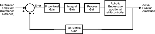
For the depth recovery experiments, both real scenes captured by the stereo camera and computer-generated surfaces were used. Five subjects were asked to observe the two images by following a suggested fixation path. The fixation points were acquired from the eye tracker during the task and the acquired depth coordinates were recorded. For motion stabilization, on the other hand, the experiments were designed to demonstrate how the gaze-contingent framework could be used to stabilize the apparent position of a moving target by controlling the compensatory movement of the stereo camera. An OpenGL synthetic stereo scene was set up in perspective projection, and a target was eccentrically oscillated in the z-axis (depth) by keeping its x- and y-axes stable. The virtual target was oscillated by transformation of the model matrix. The required movement of the camera was simulated by appropriate transformation of the view matrix, and free sinusoidal oscillation was used in this experiment. To regulate the movement of the camera, a closed feedback loop was used, as shown in . The response of the camera controller is regulated by Proportional, Integral and Derivative (PID) gains Citation[14]. As the user fixated on the target, its fixation amplitude was determined and subtracted from the preset amplitude, which corresponded to the reference distance between the camera and the target that was to be maintained as a constant. In this experiment, the positional shift of the virtual camera was dependent on the error signal fed back to the camera controller.
Figure 5. The closed feedback loop used to maintain motion tracking.
Autoregressive moving average modeling
In order to study the response of the visual system subject to oscillating visual stimuli, it is necessary to obtain a model that can closely describe the system. By collecting the stimulus and response data sets, the Steiglitz-McBride method Citation[15] was used to derive the rational transfer function of the proposed ocular vergence 3D depth-recovery system. This method is commonly referred to as ARMA modeling, which attempts to find the coefficients of the rational transfer function that approximates a given time-domain linear system. This method is based on identifying the unknown system from given input and output sequences that describe the system's behavior. The method solves for the numerator and denominator coefficients simultaneously in an attempt to minimize the signal error between the output and the given output signal. To include the effect of exogenous inputs to the system in a time-series model, the basic ARMA model can be further extended to a number of more elaborate variants, such as ARMAX (Autoregressive Moving Average with Exogenous Input). A general input-output linear model for a single output system with input u and output y can be written Citation[16]:In the above equation, ui is the input i and A, Bi, C, D and Fi are polynomials in the shift operator (z or q). The general model is defined by setting the time delays nk and the orders of the polynomials. According to the variance in use, the above equation can be reduced to a special case, e.g., for the ARMAX, Equation (4) can be confined to
Results
Depth recovery
illustrates the depths recovered by the five subjects studied. During the experiment, they were asked to scan with their eyes along the y-axis of the object. No visual markers were introduced and they were relatively free to select and fixate on image features of their choice. shows a comparative plot of the surface depths recovered from these subjects. It is evident that a relatively close correlation was achieved, demonstrating the feasibility of veridical reconstruction of the real depth. The same subjects were also asked to perform a similar task with synthetic images. This was necessary since, in the master control console of a robotic system, both live video and synthetically generated images are often present. It is therefore important to establish that similar depth reconstruction behavior can be achieved. Similarly to the previous experiment, the subjects were asked to follow a predefined path by fixating on image features of their choice, and presents the corresponding depths recovered from these subjects, with the ground-truth data being provided for comparison purposes.
Figure 6. (a) Comparative results of the reconstructed depths from the fixation paths of the five subjects studied along the tissue surface illustrated in (b). The subjects followed a predefined path starting from the bottom of the surface and moving towards the top. [Color version available online.]
![Figure 6. (a) Comparative results of the reconstructed depths from the fixation paths of the five subjects studied along the tissue surface illustrated in (b). The subjects followed a predefined path starting from the bottom of the surface and moving towards the top. [Color version available online.]](/cms/asset/f8e61198-21d4-40c7-9216-3fb5fe5acfc8/icsu_a_197035_f0006_b.jpg)
Figure 7. (a) A comparison of the recovered depths by the five subjects studied against the actual depth of the virtual surface depicted in (b). [Color version available online.]
![Figure 7. (a) A comparison of the recovered depths by the five subjects studied against the actual depth of the virtual surface depicted in (b). [Color version available online.]](/cms/asset/66c316a2-1e82-4149-bd2c-3aca0cabfc59/icsu_a_197035_f0007_b.jpg)
Motion stabilization
For motion stabilization, the subjects were instructed to keep fixating on the moving target, which would become stationary after stabilization. demonstrates the constant distance between the target and the camera that the observers were able to maintain. It is evident that the gaze-contingent camera closely compensates for the oscillation of the target. To allow for a more quantitative analysis, illustrates the regression ratios of the target and motion-compensated camera position after subtracting out the constant distance maintained. The mean and standard deviation of the regression ratio achieved for this study group were 0.103 and 0.0912, respectively.
Figure 8. (a) Gaze-contingent motion compensation where the relative shift along the depth axis corresponds to the required reference distance of the gaze-controlled camera from the target. (b) The corresponding linear regression demonstrates the intrinsic accuracy of the method. [Color version available online.]
![Figure 8. (a) Gaze-contingent motion compensation where the relative shift along the depth axis corresponds to the required reference distance of the gaze-controlled camera from the target. (b) The corresponding linear regression demonstrates the intrinsic accuracy of the method. [Color version available online.]](/cms/asset/b6e69542-f522-4dd2-808a-7dc3dbdec9f9/icsu_a_197035_f0008_b.jpg)
Table I. Error analysis comparing the gaze-contingent motion compensation performance of five subjects.
Binocular system frequency response
To assess the binocular system frequency response, experiments were carried out with six subjects. The first set of experiments investigated the oscillatory response of the binocular visual system over a frequency range. The subjects involved were asked to keep fixating on a feature of their choice on the surface of the phantom heart model. In parallel with binocular eye tracking, the robot was set to oscillations of gradually increasing frequencies along the z-axis (depth). While the 3D fixation point of a subject was tracked, the position of the robotic cameras was also recorded using the Polaris optical tracker. After data collection, ARMA modeling was used to derive the coefficients of the parametric system that describes the transfer function of the system. summarizes the response of the visual system in oscillation along the z-axis, indicating that it is accurate up to frequencies of approximately 1.8 Hz. Beyond this limit, there is considerable attenuation and noticeable phase shift.
Table II. Error analysis comparing the oculomotor response of six subjects over a range of frequencies.
Tissue deformation tracking
To assess the ability of the proposed binocular eye-tracking framework in recovering tissue deformation, the deformable phantom model was used along with an Aurora catheter-tip tracker positioned on the epicardial surface. The subjects were asked to keep fixating on a surface feature close to the Aurora sensor. While the phantom was subjected to different levels of deformation, both the fixation point and the position of the electromagnetic sensor were tracked. In , the gaze-contingent recovered deformation is compared with the actual levels reported by the sensor, demonstrating the practical accuracy of the method.
Figure 9. The recovered deformation from ocular vergence for the phantom model, where the actual deformation of the phantom heart surface as measured by an Aurora catheter-tip electromagnetic tracker is compared to the gaze-contingent reconstructed deformation. [Color version available online.]
![Figure 9. The recovered deformation from ocular vergence for the phantom model, where the actual deformation of the phantom heart surface as measured by an Aurora catheter-tip electromagnetic tracker is compared to the gaze-contingent reconstructed deformation. [Color version available online.]](/cms/asset/5f7feec4-5804-457f-a3fc-c164e2239485/icsu_a_197035_f0009_b.jpg)
To assess the in vivo value of the proposed framework, data from a robotically assisted TECAB procedure performed with the da Vinci robot were used. The video footage of the operation was played back in the stereoscopic viewer while a subject was eye-tracked. The purpose of this experiment was to demonstrate how cardiac and respiratory motion could be recovered and decoupled by using eye-tracking. shows a snapshot of the two views taken from 40 seconds of footage. A large portion of the view was occupied by the da Vinci robotic Endowrist® grasping the cardiac stabilizer just before it was positioned. During the entire sequence, the laparoscope remained stationary, and the deformed tissue area under foveation appeared in the bottom left portion of the image. What appears on the video sequence is the deforming epicardial surface with the respiratory motion principally manifested along the horizontal axis superimposed by the cardiac motion. The graphs in show the collected eye-tracking data on the x, y and z-axes. Independent component analysis with the extended Infomax algorithm was then used to decouple respiratory from cardiac motion.
Figure 10. The recovered epicardial surface deformation for a TECAB procedure. Left: A snapshot of the binocular views used in the experiment. Right: The eye-tracking-acquired tissue deformations on the x, y and z-axes. [Color version available online.]
![Figure 10. The recovered epicardial surface deformation for a TECAB procedure. Left: A snapshot of the binocular views used in the experiment. Right: The eye-tracking-acquired tissue deformations on the x, y and z-axes. [Color version available online.]](/cms/asset/28c28575-efdb-4483-97d1-5508016b9ebf/icsu_a_197035_f0010_b.jpg)
Discussion and conclusion
In this paper we have demonstrated the potential value of gaze-contingent control in robotically assisted MIS. Both spatial and temporal accuracies of the method in terms of deformation tracking and motion stabilization have been assessed with detailed phantom validation. It is worth noting that for the depth-recovery experiment some discrepancies are noticeable in the comparative depth-extraction plots, both among the participating subjects and with respect to the provided ground-truth. The reason for these discrepancies is that fixation on a predefined scan-path is difficult in practice, and deviation due to fixation jitter is difficult to avoid. However, the results derived from the subjects studied demonstrate the relative consistency of the 3D depth recovered.
For the motion stabilization experiments, it is important to note that delays in the video relay, robot communication and motor controls can potentially introduce instability into the feedback loop. The use of adaptive optics for motion stabilization can potentially minimize this effect. Another option would be to investigate the use of prediction schemes that would compensate for delay-induced instabilities Citation[17], Citation[18]. This is particularly useful for compensating for cyclic tissue deformation, which is characteristic of cardiac motion. It is also interesting to note that, for two of the subjects (2 and 5) studied for motion compensation, near-perfect compensation was achieved. These particular subjects had the opportunity to spend more time performing the experiment over several sessions, suggesting that experience of the system plays a certain role in the ability to stabilize the motion of a deforming tissue. It should be noted that a number of other issues need to be considered in the future integration of the proposed gaze-contingent framework. These include the dynamics of vergence Citation[19], Citation[20] and subject/scene-specific behavior of the eye Citation[21], Citation[22]. Other issues related to monocular preference Citation[23], visual fatigue Citation[24], and spatial errors that can arise when projecting 3D space on a 2D window Citation[25] will also have to be taken into account.
With the binocular frequency response and the deformation tracking experiments, we have demonstrated the potential of gaze-contingent soft tissue motion and deformation recovery in MIS. In this study, it was shown that the cut-off of 3D ocular vergence depth recovery with the proposed system was reached at frequencies of approximately 1.5–1.8 Hz when oscillations occur on the z-axis (depth). This corresponds to a heartbeat rate in the range of 100 bps. It is expected that the response of the visual system in oscillations on the x- and y-axes will be even better. In this case, and when depth recovery is not required, it would be possible to decouple the two eyes during eye-tracking and just use the saccadic information for one of them – preferably the dominant eye. In this way, it is possible to eliminate a large amount of noise caused by the intrinsically asymmetric dynamic behavior of the visual system during binocular coordination Citation[26]. It is also possible to obtain a better overall response by re-positioning the robotic endoscope in such a way that the principal oscillation component is shifted from z to the other two axes (x or y).
Deploying robots around and within the human body, particularly for robotic surgery, presents a number of unique and challenging problems. These arise from the complex and often unpredictable environments that characterize human anatomy. The ethical and legal barriers imposed on interventional surgical robots give rise to the need for tight integration between the operator and the robot, where interaction in response to sensing is firmly under the control of the operating surgeon. The study presented here is a first step towards this goal and to our knowledge is the first of its kind to have been conducted in normal subjects for both real and synthetic scenes.
Acknowledgments
The authors would like to thank Danail Stoyanov and Fani Deligianni for their invaluable help throughout the course of this research. The authors also wish to acknowledge the financial support from the EPSRC, the Royal Society, and the Wolfson Foundation.
References
- Wimmer-Greinecker G., Deschka H., Aybek T., Mierdl S., Moritz A., Dogan S. Current status of robotically assisted coronary revascularization. Am J Surg 2004; 188(4A Suppl)76S–82S
- Cuvillon L., Gangloff J., de Mathelin M., Forgione A. (2005) Toward robotized beating heart TECABG: Assessment of the heart dynamics using high-speed vision. Proceedings of the 8th International Conference on Medical Image Computing and Computer-Assisted Intervention (MICCAI 2005), Palm Springs, CA, October, 2005, J. S. Duncan, G. Gerig. Springer, Berlin, 551–258, Part II. Lecture Notes in Computer Science 3750
- Stoyanov D., Mylonas G. P., Deligianni F., Darzi A., Yang G-Z. (2005) Soft-tissue motion tracking in robotic MIS procedures. Proceedings of the 8th International Conference on Medical Image Computing and Computer-Assisted Intervention (MICCAI 2005), Palm Springs, CA, October, 2005, J. S. Duncan, G. Gerig. Springer, Berlin, 139–246, Part II. Lecture Notes in Computer Science 3750
- Stoyanov D., Darzi A., Yang G-Z. A practical approach towards accurate dense 3D depth recovery for robotic laparoscopic surgery. Comput Aided Surg 2005; 10(4)199–208
- Stoyanov D., Darzi A., Yang G-Z. Dense depth recovery for robotic assisted laparoscopic surgery. Proceedings of the 7th International Conference on Medical Image Computing and Computer-Assisted Intervention (MICCAI 2004), St. MaloFrance, September, C. Barillot, D. R. Haynor, P. Hellier. Springer, Berlin 2004; 41–28, Part II. Lecture Notes in Computer Science 3217
- Mon-Williams M., Tresilian J. R., Roberts A. Vergence provides veridical depth perception from horizontal retinal image disparities. Exp Brain Res 2000; 133: 407–213
- Yang G-Z, Dempere-Marco L., Hu X-P, Rowe A. Visual search: psychophysical models and practical applications. 2002; 20: 291–205, Image and Vision Computing
- Morimoto C. H., Mimica M. R.M. Eye gaze tracking techniques for interactive applications. 2005; 98: 4–24, Computer Vision and Image Understanding
- Bookstein F. L. Principal warps: Thin plate splines and the decomposition of deformations. IEEE Trans Pattern Anal Mach Intell 1989; 11(6)567–285
- Tsai R. A versatile camera calibration technique for high-accuracy 3D machine vision metrology using off-the-shelf TV cameras and lenses. IEEE J Robotics Automation 1987; 3(4)323–244
- Duchowski A., Medlin E., Cournia N., Murphy H., Gramopadhye A., Nair S., Vorah J., Melloy B. 3-D eye movement analysis. Behav Res Methods Instrum Comput 2002; 34(4)573–291
- Horn B. Robot Vision. MIT Press, Cambridge, MA 1986
- Stoyanov D., Darzi A., Yang G-Z. (2005) Laparoscope self-calibration for robotic assisted laparoscopic surgery. Proceedings of the 8th International Conference on Medical Image Computing and Computer-Assisted Intervention (MICCAI 2005), Palm Springs, CA, October, 2005, J. S. Duncan, G. Gerig. Springer, Berlin, 114–221, Part II. Lecture Notes in Computer Science 3750
- Dorf R. C., Bishop R. H. Modern Control Systems. 9th edition. Prentice Hall. 2001
- Steiglitz K., McBride L. A technique for the identification of linear systems. IEEE Trans Automatic Control 1965; 10(4)461–264
- Ljung L. System Identification Toolbox for use with MATLAB, User's Guide. www.mathworks.com
- Ortmaier T., Groger M., Boehm D. H., Falk V., Hirzinger G. Motion estimation in beating heart surgery. IEEE Trans Biomed Eng 2005; 52(10)1729–2740
- Ginhoux R., Gangloff J., de Mathelin M., Soler L., Sanchez M. M.A., Marescaux J. Active filtering of physiological motion in robotized surgery using predictive control IEEE Trans Robotics. 2005; 21(1)67–29
- Howard I. P., Allison R. S., Zacher J. E. The dynamics of vertical vergence. Exp Brain Res 1997; 116(1)153–259
- Kawata H., Ohtsuka K. Dynamic asymmetries in convergence eye movements under natural viewing conditions. Jpn J Ophthalmol 2001; 45(5)437–244
- Stork S., Neggers S. F., Müsseler J. Intentionally-evoked modulations of smooth pursuit eye movements. Hum Mov Sci 2002; 21(3)335–248
- Rottach K. G., Zivotofsky A. Z., Das V. E., Averbuch-Heller L., Discenna A. O., Poonyathalang A., Leigh R. J. Comparison of horizontal, vertical and diagonal smooth pursuit eye movements in normal human subjects. Vision Res 1996; 36(14)2189–2195
- van Leeuwen A. F., Collewijn H., Erkelens C. J. Dynamics of horizontal vergence movements: interaction with horizontal and vertical saccades and relation with monocular preferences. Vision Res 1998; 38(24)3943–2954
- Takeda T., Hashimoto K., Hiruma N., Fukui Y. Characteristics of accommodation toward apparent depth. Vision Res 1999; 39(12)2087–2097
- Wann J. P., Rushton S., Mon-Williams M. Natural problems for stereoscopic depth perception in virtual environments. Vision Res 1995; 35(19)2731–2736
- Horng J., Semmlow J. L., Hung G. K., Ciuffreda K. J. Autoregressive analysis of disparity vergence eye movements. Proceedings of the 19th Annual IEEE Northeast Conference, Newark, NJ, 1993; 69–21