
 ?Mathematical formulae have been encoded as MathML and are displayed in this HTML version using MathJax in order to improve their display. Uncheck the box to turn MathJax off. This feature requires Javascript. Click on a formula to zoom.
ABSTRACT
In this work, the mechanical behavior of as-received and hydrogenated Zircaloy-4 fuel claddings was investigated by the newly developed advanced expansion due to compression (A-EDC) test and the conventional uniaxial tension (UT) test at room temperature, in order to, respectively, understand the hydride-induced embrittlement in tube longitudinal and hoop directions. The UT experimental results showed that the mechanical strength in the longitudinal direction slightly increased with hydrogen content, whereas the maximum strain decreased greatly with hydrogen increasing. In the case of A-EDC tests, the mechanical performance in the hoop direction seemed insensitive to the hydrogen content; no obvious decline in maximum strain was observed until 800 ppm H. The comparison between these two tests clearly reveals that the hydride-induced embrittlement is preferential to occur in the longitudinal direction, compared with the sluggish response in the hoop direction, which implied the enhanced ductility anisotropy due to hydrides. In the post-tests observation, the fracture morphologies became gradually distinct for the as-received and hydrided samples examined by UT and A-EDC methods, and different orientation relationships between the applied stresses and hydrides distribution would be responsible for that distinction.
1. Introduction
Water-side corrosion is one of the most critical issues which greatly shorten the life time of zirconium (Zr) based nuclear cladding tubes. Hydrogen as one of the reaction products is absorbed into Zr matrix. Once the hydrogen concentration exceeds the solubility in Zr, the excessive hydrogen precipitates as hydrides, which impose deleterious effect on the mechanical properties of claddings. Typically, Zr hydrides have three different phases crystallographically distinct from each other: δ-, ϵ-, and γ-hydride. The most frequently observed hydride under a real nuclear reactor operation is the δ-hydride, which is the thermodynamically stable phase, whereas ϵ- and γ-hydrides are metastable phases. The formed hydrides are preferential to make the Zr-based cladding tubes more vulnerable to a brittle failure, also known as hydrogen embrittlement, generally depending on their orientation, distribution, and morphology. Previous studies have shown that various crystallographic orientations between δ-hydride and α–Zr matrix may exist and are summarized as follows: basal planes of {0001}α//(111)δ, , and
, prismatic planes of
and
, pyramidal planes of
and
, and twin planes of
,
, and
[Citation1–4]. Among the above habit planes, basal planes are commonly observed during hydride precipitation according to other surveys [Citation2,Citation4–6]. Both intra- and inter-granular hydrides have been reported in various Zr alloys. In the cold-worked and stress-relieved Zircaloy-4, the most utilized cladding materials in the pressurized water reactors during the past decades, the inter-granular hydrides orientated along tube hoop direction are dominantly formed at low hydrogen content without external load [Citation4]. Further increment of hydrogen content results in a great number of radial hydrides, promoting the continuity of interlinked hydrides and accelerate the brittle fracture to claddings. A sudden ductile-to-brittle transition has been reported when hydrogen content surpasses a critical value [Citation7,Citation8]. So far, lots of studies on the role of various stress–strain states have performed to evaluate the mechanical properties of hydrogenated Zr alloys [Citation9–12]. However, in some of these tests, materials are prepared into the plate shape by a series of treatments like cold rolling and annealing, resulting in some variations in anisotropy and even total modification of geometry with respect to the original cladding tubes.
Based on the above background, our research group developed a new testing technique named advanced expansion due to compression (A-EDC) test [Citation13] and applied it to study the mechanical property of as-received and hydrided Zircaloy-4 in hoop direction. Other than the other methods (i.e. burst test, ring compression, ring tension, etc. [Citation14–18]) posing non-uniform stress to materials, the A-EDC test can achieve a uniaxial stress–strain state in the tube hoop direction all through the testing process. Meanwhile, the conventional uniaxial tension (UT) in tube longitudinal direction was employed to examine the mechanical performance as well. By the comprehensive utilization of conventional UT (tube longitudinal direction) and the A-EDC (tube hoop) tests, this study is focused on the anisotropic performance of hydrided nuclear fuel cladding tubes. On one hand, hydride-induced ductility loss in two perpendicular tube directions will be analyzed together; on the other hand, the anisotropic performance of hydrided samples will also be comparatively discussed with the purpose to illuminate the effect of hydrides precipitation on material directionality behavior.
2. Experiments
The cold-worked and stress-relived (CWSR) Zircaloy-4 (Zr-1.3Sn-0.2Fe-0.1Cr, in wt.%) has an outer diameter of 9.5 mm and an inner diameter of 8.3 mm. Gaseous hydrogen charging was conducted at Nuclear Development Co., Japan, to prepare different target hydrogen contents: 100, 400, and 800 ppm. The surface of tubular sample was as smooth as the typical commercial grade fuel cladding tubes and was degreased by acetone before hydrogen charging. Mixed gases of H2 and Ar were injected into the furnace. This experiment was carried out at 673 K. Hydrogen absorbance was directly measured by a LOECO RH404 analyzer on the basis of hot extraction method. shows the measured hydrogen contents after hydrogen charging experiment. Hereafter, the hydrogenated samples will be called 100, 400, and 800 ppm H samples.
Table 1. Target and measured hydrogen contents. In the text, name of samples and the amount of absorbed hydrogen will be called based on the nominal (target) value of hydrogen.
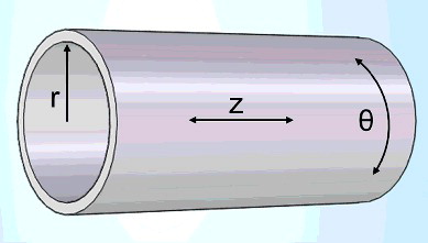
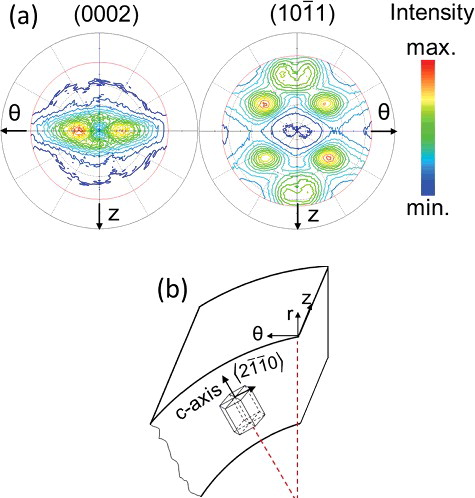
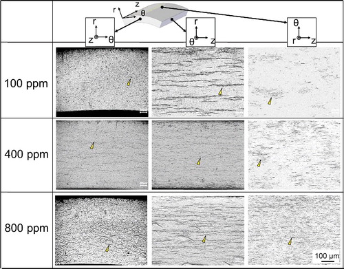
The reference system of tubular cladding was denoted by hoop direction (θ), radial direction (r), and axial direction (z), as shown in . The hydride morphology was observed by optical microscope and the samples were prepared by grinding with abrasive paper up to #2000. Then, samples were polished using colloidal silica and etched in a solution of 45% HNO3 + 45% H2O + 10% HF (in vol.%).
Figure 1. The reference system of Zircaloy-4 nuclear fuel tube: radial direction (r), hoop direction (θ), and longitudinal direction (z).
The texture microstructure of Zircaloy-4 and hydrides was characterized by X-ray diffraction (XRD) technique using Rigaku Ultima IV with Cu Kα radiation (λ = 1.54178 Å). Through constructing pole figures by Schulz reflection method [Citation19,Citation20], the detailed crystallographic texture was established. As shown in , the sample was initially mounted on a stage according to defined directions. Prior to scanning, the detector was fixed at particular 2θ degrees of 34.84° for (0002)α–Zr basal pole measurement and 36.51° for pyramid pole measurement, with reference to PDF cards of a single hexagonal-close-packed zirconium (International Center for Diffraction Data Card No. 00-005-0665). Another two factors α and β were functioned to control the scanning synergistically, where the angle α was set to tilt from 20° to ∼70° with a step size of 1°; the angle β rotated 360° with a scanning speed of 120°/min. Besides, the structure and phase analysis were carried out by XRD at 2θ angle ranging from 30° to 110° and the scan speed was 0.1°/min.
Figure 2. Schematic drawing of Schulz method in pole figures measurements.
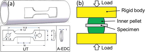
The UT in z-axis and A-EDC tests in θ-direction were conducted at room temperature by using Shimadzu AG-100kNXplus. (a,b) shows the specimen size in UT and A-EDC tests (unit: mm), and the geometry configuration of A-EDC test, respectively. The UT tensile sample was fabricated by electron discharge machining method, and the strain rate was maintained at 3.3 × 10⁻⁴ s−1. For the A-EDC test, the cladding was cut into a ring-shaped sample with 1 mm in height. It was expanded by compressing a Cu inner pellet (ϕ8 mm × h8 mm) sandwiched by a pair of rigid bodies made of yttria-stabilized zirconia; the strain rate of cladding was 2.0–4.5 × 10⁻⁴ s−1. A laser displacement measure device, Keyence TM-300, was used to measuring the deformation of A-EDC sample. This device applied a set of parallel light to illuminate the inner pellet, specimen, and rigid bodies. One can set the regions of interest in the image and record the maximum length of specimen (outer diameter) every 50 ms. The error during diameter measurement was ∼10−3 mm. Scanning electron microscopy was used for the observation of fractured samples after UT and A-EDC tests.
Figure 3. (a) Geometries and sizes of samples in UT and A-EDC tests (unit: mm); (b) the test configuration of A-EDC test.
3. Results and discussion
3.1. Anisotropic microstructure in Zircaloy-4 cladding tubes
shows the XRD spectra obtained from a 2θ varying from 30° to 110° on the z–θ plane of the 800 ppm H sample. It is noticeable that compared with the other crystal planes, the (0002) α–Zr plane exhibits the strongest intensity, indicating dominant basal poles orientated in the r direction. This can be ascribed to the tube fabrication process. The existence of δ-hydride has been confirmed by the (111)δ diffraction observed at around 32.4° as shown by the inset, and its relatively low intensity is owed to its lower volume fraction. Furthermore, (a) shows the basal and pyramid pole figures of α–Zr in Zircaloy-4. It can be seen that (0002) poles are preferentially aligned along the r direction with a split of ± 20°–30° in the hoop direction, implying a strong texture in this material. This so-named bimodal basal texture is commonly observed in sheet and industrial tubular Zr-based alloys [Citation21–25]. However, only basal pole figure is not sufficient to determine the exact orientation of grains, because crystal cells have another degree of freedom to rotate around c axis. Thereby, one more pole figure seems indispensable to confirm the exact orientation of crystals. The (101-10)α − Zr pole figure is useful to determine the orientation of grains inside cladding tubes. In a combined view of the pole figures in (a), the major crystal orientation related to the tube geometry is deduced to be that along with the certain distribution of basal poles mentioned before, a large proportion of crystals possessed that the <21¯1¯0> crystal directions are parallel to the hoop direction as illustrated in (b).
Figure 4. X-ray diffraction patterns of the 800 ppm H Zircaloy-4 sample. Standard diffraction peaks of α-zirconium and ZrH1.66 have employed to index diffraction peaks.
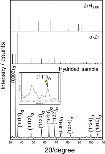
Figure 5. (a) Pole figures of (0002)α- − Zr and in Zircaloy-4 measured by XRD; (b) schematic drawing of the orientation of one unit crystal inside cladding.
3.2. Anisotropy in mechanical behavior and its effect on degradation
3.2.1. Uniaxial tensile in tube longitudinal direction
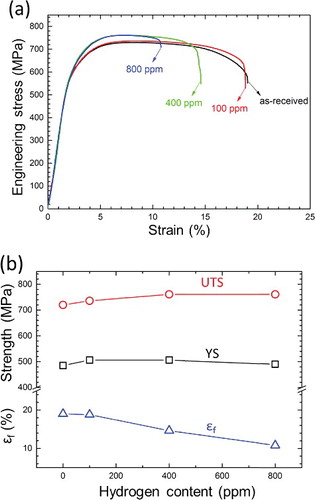
The results of UT tests in the tube longitudinal direction (z) axis for as-received and various hydrided Zircaloy-4 samples are shown in . Through stress–strain curves in (a), an obvious hydride-induced embrittlement, as indicated by the gradually shortened strain at fracture, has been observed with the increment of hydrogen content. (b) shows that the absorption of 800 ppm H greatly reduced the strain at fracture of Zircaloy-4 from 19.5% to 10.8%. A material yielding is generally regarded as the onset of plastic deformation triggered by the movement of dislocations under a criteria shear stress or larger [Citation26]. Because there are no pronounced yield points in the stress–strain curves, the 0.2% offset yield strengths (YS) have been employed instead. A slight strengthening caused by hydrides has been observed, and that is, the ultimate tensile strength (UTS) and YS became larger with raising hydrogen content, and this result is consist with Tung's research on Zircaloy-4 sheets [Citation27]. Undoubtedly, the more the hydrogen is charged into materials, the more inter- and intra-granular hydrides will form inside cladding tubes. Hydrides formation could introduce several aspects of influences on materials. First, the transformation from zirconium to hydride can result in large local volume expansion, on account of the physical density differences (ρα--Zr = 6.506 g/cm3 > ρδ-hydride = 6.366 g/cm3). Revealed by literatures [Citation28,Citation29], when a hydrogen atom is implanted in a tetrahedral site of a hexagonal close-packed crystal cell, the volume could increase approximately by 3 Å3. Second, both Young's modulus and shear modulus of δ-hydride are dramatically larger than those of α–Zr [Citation30]. Thereby, the precipitated hydrides can play roles of obstacles to impede dislocation motion. Therefore, the combination of precipitation strengthening, strain strengthening, and grain boundary strengthening caused by hydride formation might be accounted for the strength augment in the hydrogenated Zircaloy-4 samples at low hydrogen level. However, in the case of large hydrogen concentration, the hydrides form net-like configuration, which provide more cracking sites on the hydride–matrix interfaces, promoting cracks propagation and further claddings failure at relative low strains.
Figure 6. (a) The stress–strain curves and (b) a comparison of yield strength (YS), ultimate tensile strength (UTS), and strain at fracture (ϵf) for as-received and hydrided Zircaloy-4 samples.
3.2.2. A-EDC tests in tube hoop direction
shows the experimental results from A-EDC tests. In (a), the load-height displacement curves present similar results among as-received and hydrided samples, despite that the curves end at different strains depending on hydrogen contents. It demonstrates that the energy consumed by samples expansion is nearly equal. On the other hand, the samples also exhibit the approximate changing process of hoop strains regardless of the hydrogen contents as indicated by (b). Spikes are noticeable in the load-height displacement curves around 6 mm. It is due to the manual operation of removal of jig that supports the sample until the obstruction of the initial clearance gap with the inner pellet. The hoop strain rate during tests is not constant, but ranges from 2 × 10⁻⁴ to 4.5 × 10⁻⁴ s−1. For as-received Zircaloy-4, the 0.2% YS and UTS derived from A-EDC tests are ∼836 and ∼1037 MPa, respectively [Citation31], which are larger than the value in UT tests. The differences of grain size and crystal orientation in different directions could be accounted for that. By combined analysis of (a,b), it could be inferred that the strength in the hoop direction perhaps was not intensively affected by hydrides precipitation.
Figure 7. (a) Load-height displacement, (b) hoop strain-time relation, and (c) maximum hoop strain-hydrogen content curves for as-received, 100, 400, and 800 ppm H samples.
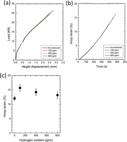
(c) shows the hoop strain at fracture correlated with hydrogen content. Differently from the apparent reduction of total elongation at fracture in UT tests, it was interesting to notice that an obvious drop on the strain at fracture in the hoop direction was not observed by ∼800 ppm H, indicating that hydrogenation-induced embrittlement phenomena happened much easier along the longitudinal direction rather than the circumferential direction in Zircaloy-4 cladding tube. It implies that the hydrides formed in Zircaloy-4 cladding tube are preferential to deteriorate the ductility in the axial direction, whereas this embrittlement is not sensitive in the hoop direction until ∼800 ppm H. The insensitive reaction with respect to hydrogenation embrittlement in the hoop direction of Zircaloy-4 cladding tube has also been revealed by tube burst and ring tensile tests. In both methods, the tube hoop directional performance is of the primary research interest for better understanding a pellet-clad mechanical interaction (PCMI) case. The burst test at room temperature by Nagase et al. reveals that the hoop strain at fracture can reach nearly constant in the case of low hydrogen content (<300 ppm) [Citation14]; moreover, the optimized ring tension test has also presented a stable fractured hoop strain for the hydrided Zircaloy-4 at hydrogen content below 500 ppm [Citation32]. Noticeably, the fractured hoop strain of sample with minor hydrogen (100 ppm) is slightly higher than that of the as-received sample. This phenomenon has also been found in some previous studies, such as tube burst and ring tension tests [Citation14,Citation33,Citation34]. Since Zircaloy-4 is in a CWSR state, this abnormal behavior could probably arise from the hydrogen charging procedure conducted at 673 K. This temperature might alleviate the residual strains and stresses inside materials to a lower level.
3.2.3. Relation of maximum strain ratio ϵθ/ϵz and hydrogen content
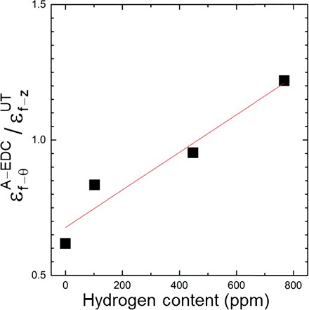
shows the ratio of fractured hoop strains in A-EDC tests to the fractured longitudinal strains in UT tests in correlation with hydrogen content. It can be found that this ratio steadily increases with the increasing of hydrogen content. This result manifests that in comparison with the hydrogen embrittlement in tube hoop direction, Zircaloy-4 cladding tube loses much more ductility in tube longitudinal direction with increasing hydrogen content. The strain at fracture during a mechanical testing is generally influenced by various factors, such as strain rate, sample thickness, gauge length, etc. In this research, strain rates may be not the critical factor since they are at the same order magnitude (∼10−4 s−1) during UT and A-EDC tests; on the other hand, the specimen thickness is the same, namely, the wall thickness of cladding tube. With respect to the sample assessed via the A-EDC test, its circumferential perimeter can be defined as the gauge length that is approximately 28 mm, nearly six times the value used in the UT experiment. Differently, the previous studies have reported that a larger uniform elongation as well as a post-necking elongation is anticipated when the gauge length of sample becomes smaller [Citation35–37]. At initial tests, the ratio ϵθ/ϵz for as-received sample is ∼0.6; however, this ratio is slowly deviated with the further accumulation of hydrogen, which should be attributed to be a combined impact of hydride precipitation and material intrinsic anisotropy. Furthermore, deriving from the raise of strains ratio ϵθ/ϵz, it is reasonable to conclude that the hydride precipitation may not only cause a prominent loss of ductility to the cladding as a whole, but also lead to different ductility loss in tube longitudinal and hoop directions, which means the anisotropic mechanical properties of cladding tubes have been enhanced through hydrogenation.
Figure 8. The ratio of maximum hoop strain (A-EDC) to longitudinal strain (UT), as a function of hydrogen content.
3.3. Hydride morphologies and fractography
Three tube geometrical surfaces have been overall examined in order to fully reveal the spatial distribution of hydrides. In , various hydride morphologies are observed on different planes by optical microscope. The triangles in indicate the typical morphologies of different hydrides on three typical planes. Obviously, hydrides have features of a kinked shape on r–θ plane whereas a linear shape on r–z plane and a random appearance on z–θ plane. Hydride nucleation frequently develops on grain boundaries, which are principally regarded as the rapid diffusion routes for hydrogen [Citation32,Citation38]. Except that, grain orientation can also intensively determine the hydride formation. A theoretical analysis has elucidated that if a grain orientation is parallel to the habit plane, the critical hydride nucleation energy is expected to decrease [Citation39]. Accordingly, the morphologies of hydrides in this research can be the result of the defined grain shapes and texture in Zircaloy-4. In the manufacturing process, the cold rolling and stress relief process would inevitably produce elongated grains in one dimension (the z direction). The elongated grain with favorable orientation for hydride nucleation could provide more space for growing long precipitates. When the hydrogen increases, large density of hydrides can occupy more grain boundaries as well as grain interiors, finally forming a net-like configuration with a high degree of continuity.
Figure 9. Hydride distribution on different tubular planes. The locations of hydrides have been indicated by the triangles.
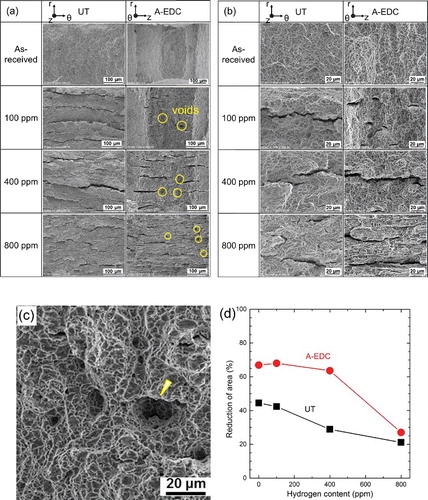
shows fractured surfaces and the corresponding reduction of area (RA) percentages for as-received and hydrided Zircaloy-4 samples after UT and A-EDC tests. (a) shows that in the UT tests, a high density and long size of cracks can be observed along tube hoop direction, while in the post-test observation of A-EDC, the cracks with smaller length are arranged in the tube longitudinal direction. Since cracks are usually recognized to be the reason of inconsistent deformation between hydrides and their neighbored gains, these distinctions should be associated with hydride distribution and morphology. Under low hydrogen content level (<450 ppm), samples exhibit distinctly necking due to shear stress in the A-EDC tests. Furthermore, the degree of necking, which can be identified by the slope between the edge and the center, is found to gradually diminish or even disappear in the sample with 800 ppm hydrogen. The neighbor hydride-induced crack could coalesce with each other feasibly. If the stress is high enough to fracture the surrounded matrix, the crack length has been tremendously extended, as indicated in the UT tests. On the contrary, the samples tested by A-EDC also show the same tendency but much less severe. Some cavities, as marked by the circles (further shown in (c) for 100 ppm H sample in A-EDC), have been found on the regions near crack tips in hydrided samples after A-EDC tests, which perhaps result from the combination of vicinal cracks. (b) shows the high magnified morphologies of fractured surfaces. For the as-received Zircaloy-4 tested by UT and A-EDC at room temperature, a ductile fracture mechanism is revealed by the aggregation of dimples, which are typically caused by micro voids coalescence. The cracks on the surface in UT tests are mainly in the tube hoop direction, while propagating in the tube longitudinal direction as revealed in the A-EDC tests. In the hydrided samples, large amount of fine dimples have also been observed on the regions away from hydride-induced cracks, suggesting the reservation of ductile property in the remaining Zr matrix. Besides, the junctions of nearby hydride-induced cracks have generated numerous large-sized cracks in all the tests. Radial hydrides are much more dangerous because of the occurrence of Mode Ι fracture under hoop stress, which can noticeably facilitate the extension of thickness-through cracks. In the present research, radial cracks are not visible in the samples until the hydrogen content increases to around 800 ppm. For the Zircaloy-4 sample with 800 ppm H, the fracture morphology after A-EDC test is different from that after UT test. In particular, the fracture in A-EDC shows a majority of long ductile tearing in the tube longitudinal direction and some cleavage facets isolated from the surrounding ductile portions. A post-test observation of Zircaloy-4 and HANA with 700 ppm H by Kim also reveals the similar morphologies [Citation34]. (d) presents the RA in UT and A-EDC experiments. With the hydrogen increasing to 800 ppm, there is an obvious decrement of RA in all the tests. Compared with the sample tested by UT, the one examined by A-EDC first exhibits a much smaller decline of RA and then greatly drops with further hydrogen accumulation. Finally, a RA of about 25% is reached in the case of 800 ppm H for both UT and A-EDC tests.
Figure 10. Fracture morphologies at (a) low magnification and (b) high magnification. (c) The magnified view of voids in 100 ppm sample after A-EDC tests. (d) The reduction of area percentage of as-received and hydrided Zircaloy-4 after UT and A-EDC tests.
4. Conclusions
With the assistance of the newly established A-EDC method and the conventional UT tests, the hydride-induced embrittlement of CWSR Zircaloy-4 in tube longitudinal and hoop directions has been systematically studied and discussed. The main results are summarized as follows:
Hydrides are preferentially precipitated along tube circumferential direction due to the textured microstructure of cladding tubes. In the UT tests, the tensile stress is perpendicular to the chain-shaped hydrides, resulting in a mild increment in mechanical strength (YS and UTS) and a decline of strain at fracture with the increment of hydrogen content. On the contrary, the stress in A-EDC tests is parallel to the chain-shaped hydrides, where the strain at fracture maintains nearly a constant under the hydrogen content below 400 ppm. In addition, the YS and UTS in A-EDC tests are also not significantly influenced by hydrogen content.
For as-received Zircaloy-4, the smaller gauge length of sample in the UT exhibits a larger maximum strain when compared with the specimen examined by the A-EDC test. Nevertheless, with increasing hydrogen content, hydride-induced embrittlement in tube longitudinal direction seems to be more rigorous than that in tube hoop direction, which in turn would enhance the mechanical anisotropy of textured Zircaloy-4.
Fracture morphologies of as-received and hydrided samples were different in UT and A-EDC tests, as a consequence of different orientation relationship between applied stresses and hydrides distributions. The UT test shows a necking around tube hoop direction, while the necking phenomenon has been examined in tube longitudinal direction by the A-EDC test, implying the difference of fracture process between the two tests. With the further accumulation of hydrides, a growing number of hydride-induced cracks have formed on the fracture surface. Meanwhile, obvious ductility loss has been observed for the 800 ppm H sample in both tests.
Acknowledgments
This work is supported by the project of ‘R&D of nuclear fuel cladding materials and their environmental degradations for the development of safety standards’ entrusted to Tohoku University by Ministry of Education, Culture, Sport, Science and Technology of Japan (MEXT), and ‘Study on hydrogenation and radiation effects in advanced nuclear fuel cladding materials’ conducted under the Strategic Promotion Program for Basic Nuclear Research by MEXT.
Disclosure statement
No potential conflict of interest was reported by the authors.
References
- Bailey JE. Electron microscope observations on the precipitation of zirconium hydride in zirconium. Acta Metall. 1963;11:267–280.
- Qin W, Szpunar JA, Kiran Kumar NAP, et al. Microstructural criteria for abrupt ductile-to-brittle transition induced by δ-hydrides in zirconium alloys. Acta Mater. 2014;81:219–229.
- Kunz FW, Bibb AE. Habit plane of hydride precipitation in zirconium and zirconium-uranium. Trans Metall Soc AIME. 1960;218:133–135.
- Suman S, Khan MK, Pathak M, et al. Hydrogen in Zircaloy: mechanism and its impacts. Int J Hydrog Energy. 2015;40:5976–5994.
- Une K, Nogita K, Ishimoto S, et al. Crystallography of zirconium hydrides in recrystallized Zircaloy-2 fuel cladding by electron backscatter diffraction. J Nucl Sci Technol. 2004;41:731–740.
- Perovic V, Weatherly GC, Simpson CJ. Hydride precipitation in α/β zirconium alloys. Acta Metall. 1983;31:1381–1391.
- Bai J, Prioul C, Lansiart S, et al. Brittle fracture induced by hydrides in zircaloy-4. Scr Metall Mater. 1991;25:2559–2563.
- Huang JH, Ho CS. Effect of hydrogen gas on the mechanical properties of a zirconium alloy. Mater Chem Phys. 1994;38:138–145.
- Fan Y, Koss DA. The influence of multiaxial states of stress on the hydrogen embrittlement of zirconium alloy sheet. Metall Trans A. 1985;16:675–681.
- Puls MP. The influence of hydride size and matrix strength on fracture initiation at hydrides in zirconium alloys. Metall Trans A. 1988;19:1507–1522.
- Cockeram BV, Hollenbeck JL. The role of stress-state on the deformation and fracture mechanism of hydrided and non-hydrided Zircaloy-4. J Nucl Mater. 2015;467( Part 1):9–31.
- Glendening A, Koss D, Motta A, et al. Failure of hydrided Zircaloy-4 under equal-biaxial and plane-strain tensile deformation. J ASTM Int. 2005;2:1–16.
- Abe H, Abe T, Kishita S, et al. Development of advanced expansion due to compression (A-EDC) test method for safety evaluation of degraded nuclear fuel cladding materials. J Nucl Sci Technol. 2015;52:1232–1239.
- Nagase F, Sugiyama T, Fuketa T. Optimized ring tensile test method and hydrogen effect on mechanical properties of Zircaloy cladding in hoop direction. J Nucl Sci Technol. 2009;46:545–552.
- Busser V, Baietto-Dubourg M-C, Desquines J, et al. Mechanical response of oxidized Zircaloy-4 cladding material submitted to a ring compression test. J Nucl Mater. 2009;384:87–95.
- Hermann A, Yagnik S, Gavillet D. Effect of local hydride accumulations on Zircaloy cladding mechanical properties. Paper presented at: Zirconium in the Nuclear Industry. 15th International Symposium; 2007 Jun 24–28; Sunriver, OR.
- Garde AM, Smith GP, Pirek RC. Effects of hydride precipitate localization and neutron fluence on the ductility of irradiated Zircaloy-4. Paper presented at: Zirconium in the nuclear industry. 11th International Symposium; 1996; Garmisch-Partenkirchen, Germany.
- Desquines J, Koss DA, Motta AT, et al. The issue of stress state during mechanical tests to assess cladding performance during a reactivity-initiated accident (RIA). J Nucl Mater. 2011;412:250–267.
- Chateigner D, Germi P, Pernet M. Texture analysis by the Schulz reflection method: defocalization corrections for thin films. J Appl Crystallogr. 1992;25:766–769.
- Nagao K, Kagami E. X-ray thin-film measurement techniques_VII_Pole figure measurement. Rigaku J. 2011;27:6–14.
- Wassermann G, Grewen J. Texturen metallischer Werkstoffe [Textures of metallic materials]. Berlin: Springer; 1962.
- Dillamore IL, Roberts WT. Preferred orientation in wrought and annealed metals. Metall Rev. 1965;10:271–380.
- Tenckhoff E. Operable deformation of textured Zircaloy tubing. In: Schemel JH, Rosenbaum HS, editors. Zirconium in Nulcear Applications; 1973 Aug 21–24; Porland, OR. Philadelphia: ASTM International; 1974. p. 179–199.
- Ciurchea D. Texture induced anisotropy in Zircaloy-4 tubes. J Nucl Mater. 1985;131:1–10.
- Grange M, Besson J, Andrieu E. Anisotropic behavior and rupture of hydrided Zircaloy-4 sheets. Metall Mater Trans A. 2000;31:679–690.
- Dieter GE. Mechanical metallurgy. New York (NY): McGraw-Hill Book Company; 1961.
- Tung H-M, Chen T-C, Tseng C-C. Effects of hydrogen contents on the mechanical properties of Zircaloy-4 sheets. Mater Sci Eng A. 2016;659:172–178.
- Udagawa Y, Yamaguchi M, Abe H, et al. Ab initio study on plane defects in zirconium–hydrogen solid solution and zirconium hydride. Acta Mater. 2010;58:3927–3938.
- Zanellato O, Preuss M, Buffiere J-Y, et al. Synchrotron diffraction study of dissolution and precipitation kinetics of hydrides in Zircaloy-4. J Nucl Mater. 2012;420:537–547.
- Yamanaka S, Yoshioka K, Uno M, et al. Thermal and mechanical properties of zirconium hydride. J Alloy Compd. 1999;293–295:23–29.
- Zhao Z, Kunii D, Abe T, et al. Study of the mechanical properties of Zircaloy-4 cladding tube by advanced expansion due to compression (A-EDC) test. Mater Trans. 2017;58:46–51.
- Bloch J, Jacob I, Mintz MH. The effect of vacuum annealing on the hydriding kinetics of zirconium. J Alloy Compd. 1993;191:179–186.
- Nagase F, Fuketa T. Investigation of hydride rim effect on failure of Zircaloy-4 cladding with tube burst test. J Nucl Sci Technol. 2005;42:58–65.
- Kim JH, Lee MH, Choi BK, et al. Effect of the hydrogen contents on the circumferential mechanical properties of zirconium alloy claddings. J Alloy Compd. 2007;431:155–161.
- Zhao YH, Guo YZ, Wei Q, et al. Influence of specimen dimensions on the tensile behavior of ultrafine-grained Cu. Scr Mater. 2008;59:627–630.
- Zhao YH, Guo YZ, Wei Q, et al. Influence of specimen dimensions and strain measurement methods on tensile stress–strain curves. Mater Sci Eng A. 2009;525:68–77.
- Sergueeva AV, Zhou J, Meacham BE, et al. Gage length and sample size effect on measured properties during tensile testing. Mater Sci Eng A. 2009;526:79–83.
- Bloch J, Mintz MH. Kinetics and mechanisms of metal hydrides formation – a review. J Alloy Compd. 1997;253–254:529–541.
- Qin W, Kiran Kumar NAP, Szpunar JA, et al. Intergranular δ-hydride nucleation and orientation in zirconium alloys. Acta Mater. 2011;59:7010–7021.