
ABSTRACT
Looking ahead to final disposal of high-level radioactive waste arising from further utilization of nuclear energy, the effects of high burn-up of light-water reactors (LWR) with UO2 and MOX fuel and extended cooling period of spent fuel on waste management and disposal were discussed. It was assumed that the waste loading of waste glass is restricted by three factors: heat generation rate, MoO3 content, and platinum group metal content. As a result of evaluation for effects of extended cooling period, the waste loading of waste glass from both UO2 and MOX spent fuel could be increased in the current vitrification technology. For the storage of waste glass from MOX spent fuel with higher waste loading, however, those waste glass require long storage period prior to geological disposal because decay heat of 241Am contributes significantly. Therefore, the evaluation of effects of Am separation on the storage period was performed. Furthermore, heat transfer calculation was carried out in order to evaluate the temperature of buffer material in a geological repository. The results showed, 70 to 90% of Am separation is sufficiently effective in terms of thermal feasibility of a repository.
1. Introduction
The amounts of spent fuel stored in the facilities at nuclear power plants and Rokkasho reprocessing plant in Japan have been increasing along with an extension of the cooling period. The extension of the cooling period of spent fuel causes major changes in its characteristics. Moreover, higher burn-up operation, and usage of mixed oxide (MOX) fuel also affect the characteristics of spent fuel. Therefore influences of the changes in spent fuel properties on the storage and feasibility of geological disposal concept are necessarily evaluated in order to find subjects and solutions for further utilization of nuclear energy. As one of solutions, the introduction of advanced fuel cycle technology has been discussed. Some works such as evaluation of partitioning and transmutation technology for the amounts of high-level radioactive waste and disposal area reduction [Citation1,Citation2], assessment of high-level waste characteristics arising from various fuel-cycle options[Citation3], and performance analysis of waste management influenced by higher burn-up, extension of the cooling period of spent fuel, and minor actinides (MA) separation [Citation4] have been reported based on the assessment of various fuel cycle scenarios. In the paper reported by Y. INAGAKI et al. [Citation4]., the authors declared the number of glass units with respect to current vitrification technology, that is in consideration with heat generation rate, MoO3 content, platinum group metal (PGM) content. They concluded that the higher heat generation from minor actinides, especially 241Am (americium), in MOX spent fuel is one of important factors to be considered from the viewpoint of waste management. In addition, some assessments to dispose efficiently the high-level liquid waste (HLLW) arising from MOX fuel reprocessing have been carried out. In the report by ANDRA[Citation5], the feasibility of geological disposal of vitrified waste forms generated by a mixture of 15% MOX fuel and 85% UO2 fuel was evaluated.
In this study, waste loading of waste glass considering the current vitrification technology was evaluated, then the properties of waste glass and influences by Am separation with various efficiency on the heat generation rate of waste glass were discussed in terms of waste management prior to geological disposal. Furthermore, the temperature of buffer material in a geological repository was evaluated in order to discuss the feasibility of geological disposal and effectiveness of Am separation.
2. Calculation methods and assumption about vitrification process
2.1. Burn-up and decay calculation
The nuclide constituents and decay heat generated in spent fuel per ton of heavy metal (THM) in a 17 × 17 pressurized water reactor assembly were calculated by the ORIGEN-ARP [Citation6]. The burn-up was 55 and 70 GWd/THM for UO2 fuel, 28, 33, and 45 GWd/THM for MOX fuel. The cooling period of spent fuel before reprocessing was 4, 10, 20, and 30 years for both fuels. The impurity and isotope composition of UO2 fuel shown in Table S1 and Table S2 in Supplemental Online Material, respectively, are adopted in this calculation [Citation7,Citation8]. The initial composition of MOX fuel is shown in Table S3 in Supplemental Online Material [Citation4]. The calculation conditions for UO2 fuel and MOX fuel are summarized in Table S4 in Supplemental Online Material. In ORIGEN-ARP, the maximum enrichment values of fuel are limited to 6.0wt% for UO2 fuel and 10wt% Pu for MOX fuel. Therefore, their enrichment values were used for UO2 fuel burn-up of 70 GWd/THM and MOX fuel burn-up of 45 GWd/THM.
2.2. Reprocessing condition
Spent fuels discharged from reactors and cooled for several years are reprocessed in order to extract uranium and plutonium. Through the reprocessing process, HLLW is generated. In Japan, liquid fed joule-heated ceramic melter (LFCM) is adopted to immobilize HLLW into a borosilicate matrix for safe storage and disposal. The vitrified waste forms will be stored for several decades to lower decay heat, and then will be disposed of in a geological disposal tunnel excavated in a suitable host rock formation. In this study, the fraction of elements in HLLW by reprocessing process was assumed as follows.
Fraction of U and Pu remained in HLLW was assumed to 0.422% and 0.548%, respectively [Citation9]. In addition, volatile constituents like H, C, I, Cl, noble gas (He, Ne, Ar, Kr, Xe, Rn) was assumed to be fully recovered from HLLW[Citation9]. Contribution of burnable poison such as Gd2O3 and corrosion products to constituents of HLLW was not considered.
2.3. Waste loading of waste glass
It assumes that HLLW generated from reprocessing is immediately vitrified. The waste loading of waste glass is determined with following requirements.
It is assumed that weight of a waste glass is 400 kg, and the weight of a vitrified waste form consisting of a waste glass with a stainless steel canister is 500 kg. One bottle of waste glass is defined as glass unit.
The content of sodium oxide (Na2O) is important with respect to the flow-out-performance of glass melter. Generally, the higher Na2O content in the glass means the lower viscosity of melt of the glass. In this study, the content of sodium was compensated in order to meet the 10wt% (40 kg) of Na2O content per glass unit. Amounts of compensated Na2O was regarded as waste constituents.
The upper limit of waste loading of waste glass was assumed to be determined with heat generation rate, content of MoO3 and that of PGM. From an aspect of heat generation rate, if heat generation rate makes the temperature of waste glass get higher than glass transition temperature like 500 to 520°C, it can cause degradation of chemical durability of waste glass due to phase transition[Citation10]. A cooling ability for vitrified waste forms in the temporary storage is determined by temporary storage facility design, and heat generation rate per glass unit should be controlled less than 2.3 kW/glass unit when the waste glass is formed in the case of current Japanese facility [Citation10,Citation11]. Next, molybdenum has a low solubility for borosilicate glass, and it can produce yellow phase in the waste glass, which is water-soluble substance. Thus, radionuclides in yellow phase could be easily dispersed into an environment by contacting with groundwater. In addition, the low solubility of PGM for glass causes precipitations in glass melter. When it is sedimented on the shoulder and bottom of glass melter, performance of flow out of glass gets worse. Therefore, there is much research about solubility of these elements for glass [Citation12,Citation13]. In this study, waste loading was determined with all of the following limits[Citation4]. PGM content was calculated by summation of ruthenium, rhodium, and palladium metals.
Heat generation rate ≤ 2.3 kW/glass unit
MoO3 content ≤ 1.5wt%/glass unit
PGM content ≤ 1.25wt%/glass unit
2.4. Geological disposal condition
Thermal analysis of the near-field of a geological repository was carried out, based on the properties of waste glass, which was stored for 50 years to reduce decay heat. COMSOL Multiphysics commercial code was used for heat transfer calculation [Citation14].
2.4.1. Analysis model of geological repository
The repository with vertical emplacement concept in crystalline rock (hard rock) at the depth of 1,000m below the surface [Citation11] was assumed for the thermal analysis model. The geothermal gradient was assumed to be 3°C/100 m. For the initial and boundary conditions, the ground surface and the bottom surface were considered as an isothermal boundary at 15°C and 51°C, respectively. The model in horizontal plane extends from the center of the vitrified waste form to one half of waste spacing in the disposal tunnel. The boundary conditions of the vertical boundary are adiabatic, in consideration of emplacement of vitrified waste forms at a certain interval. Occupied area used for design of a geological repository is given by the product of the disposal tunnel spacing (xD in Figure S1 in Supplemental Online Material) and the waste package pitch (y in Figure S1 in Supplemental Online Material). The temperature rise of the repository induced by heat generation of waste glass is controlled by these parameters. When it meets heat restriction of geological repository, the minimum disposal tunnel spacing and waste package pitch are determined by the mechanical stability of disposal tunnel. The previous report [Citation11] describes that the minimum waste package pitch is 4.44m and the minimum disposal tunnel spacing is 10m in the case of vertical emplacement method. Therefore, the minimum occupied area per waste package is 44.4m2. Furthermore, the report [Citation11] revealed, if the occupied area per a waste package is same, the effect of difference of disposal tunnel spacing on temperature of waste package is negligibly small. Therefore, disposal tunnel spacing is fixed to 10 m, and waste package pitch is varied in this study.
2.4.2. Detailed geometry of near-field in geological repository and thermal properties
The thermal analysis taking into account the presence of a canister and a helium-filled zone in the upper part of canister was carried out to evaluate the temperature of buffer material under the various occupied area. The upper temperature limit of buffer material is set to 100° C to avoid alteration of buffer material in accordance with the report [Citation11]. The cross-sectional system for analysis is shown in Figure S2 in Supplemental Online Material. It is assumed that the outer diameter of vitrified waste form is 430 mm and there are no gaps between the vitrified waste form and overpack. As considering the emplacement in an actual repository, gaps may be produced between the overpack and buffer material, and the buffer material and host rock. However, it is reported the gaps have little effect on the maximum temperatures in the buffer material[Citation11]. So analysis without gap was carried out. Table S5 in Supplemental Online Material shows the geometry parameters and thermal properties used for this calculation [Citation15,Citation16]. The vitrified waste form is composed of waste glass and stainless steel canister. Therefore, in this study, parameters of waste glass and canister are used for the calculation. The evaluated duration of time in this calculation was 1,000 years after the emplacement of vitrified waste forms in the repository, and maximum temperature of buffer material at the boundary between overpack and buffer material was evaluated.
3. Results and discussion
3.1. Characterization of spent fuel
3.1.1. Heat generation rate of spent fuel
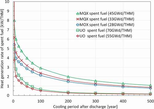
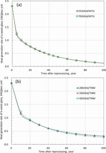
show the heat generation rate of UO2 and MOX spent fuel respectively, as a function of time for 500 years after discharge from the reactor. The heat generation rates of both fuel types increase with increase of burn-up. Moreover, it is noted that the attenuation behavior for heat generation rate was also slightly changed as a function of burn-up.
Figure 1. Evolution of heat generation rate of UO2 and MOX spent fuel per THM.
3.1.2. Contribution of minor actinides in spent fuel to heat generation rate
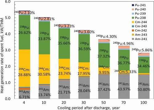
The composition of spent fuel changes during cooling period. In this section, contribution of MA which generates heat over long period is discussed. and show the contribution of minor actinides, uranium, plutonium, and fission products to the heat generation rate as a function of the cooling period of spent fuel for UO2 fuel with burn-up of 70 GWd/THM and MOX fuel with burn-up of 45 GWd/THM, respectively. For the UO2 spent fuel, contribution of MA (Np + Am + Cm) to heat generation rate become significant, namely from about 11.6% at 4 years cooling period to 37.8% at 100 years cooling period after discharge, though mass of MA in UO2 spent fuel is about 0.2 wt% at 4 years cooling period. As prolonging the cooling period of spent fuel, the heat generation rates of Am and Np increase, on the other hand that of Cm decrease. In the case of MOX spent fuel (see ), heat generation rates of those minor actinides behave in the same as the case of UO2 spent fuel. However, the total heat generation rate of minor actinides in the MOX spent fuel is much higher than that in UO2 spent fuel because the mass of minor actinides in MOX spent fuel is about 0.8wt% at 4 years cooling period, four times as large as amount of minor actinides in UO2 spent fuel. Therefore, in order to clarify the contribution of minor actinides in detail, the evolution of heat generation rate of transuranium isotopes in MOX spent fuel was discussed as shown in . As the representatives of transuranium isotopes, 241Am (T1/2 = 432.2y), 244Cm (T1/2 = 18.1y), and 238Pu (T1/2 = 87.7y) are listed [Citation17]. The increase of total amounts of 241Am in spent fuel came from beta decay of 241Pu (T1/2 = 14.29y) [Citation17]. 238Pu generating from alpha decay of 242Cm (T1/2 = 162.8d) significantly contributes for long-term to heat generation rate of spent fuel [Citation17]. It is assumed to reprocess MOX spent fuel in this study, but decay heat of 238Pu contributes significantly to heat generation rate of MOX spent fuel in the case of direct disposal of MOX spent fuel. From these results, it can be assumed that the decrement of heat generation rate of waste glass generated from spent fuel cooled for long period cannot be expected due to high amounts of long half-life nuclides in the waste glass, especially 241Am. Therefore, the effects of extended cooling period of spent fuel on a management of waste glass were discussed in the following sections.
Figure 2. Contribution of minor actinides in UO2 spent fuel (70GWd/THM) on heat generation rate.
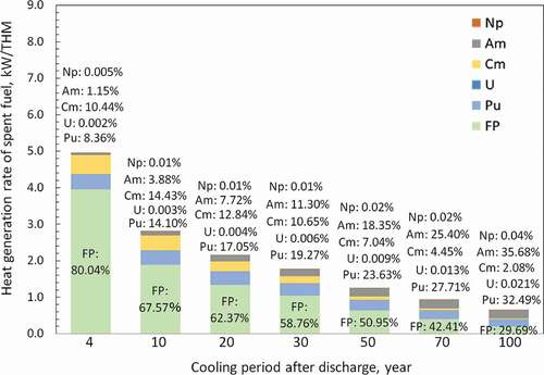
Figure 3. Contribution of minor actinides in MOX spent fuel (45GWd/THM) on heat generation rate.
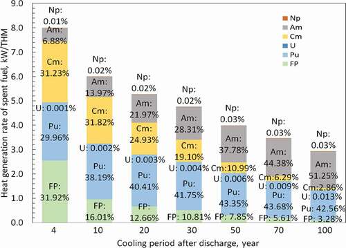
Figure 4. Contribution of transuranium isotopes in MOX spent fuel (45GWd/THM) on heat generation rate.
3.2. Amounts of waste glass
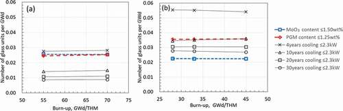
Spent fuels are reprocessed, after some cooling period to decrease its heat generation rate. The previous report [Citation4] evaluated higher burn-up operation and extension of cooling period of spent fuel on the viewpoint of the number of glass units per THM and GWd. Therefore, in order to discuss the effects of extended cooling period on the waste loading of waste glass, the number of glass units per THM and GWd for heat generation rate of spent fuel cooled for 4, 10, 20, and 30 years, content of molybdenum oxide and PGM were evaluated, which are restriction factors for waste loading and performance of LFCM. and show the number of glass units per THM and GWd in case of UO2 and MOX fuel reprocessing. It is found that the number of glass units per THM increase according to higher burn-up operation because the heat generation rate, Mo and PGM content of spent fuel per THM increase. On the other hand, if the number of glass units are discussed in terms of electric power generation, the heat generation rate, Mo and PGM content of spent fuel per GWd does not change appreciably in spite of higher burn-up operation. In the case of 4 years cooling period for both UO2 and MOX spent fuels, restriction factor is heat generation rate. In the case of a long-term cooling period, however, the heat generation rate of spent fuel per THM decreases, then waste loading can be increased and restriction factor is controlled by MoO3 content for the waste glass from UO2 spent fuel and PGM content for the waste glass from MOX spent fuel. shows the waste loading, the number of glass units per THM, and restriction factors at each burn-up and cooling period. About 20.5 to 22.0 wt% of waste loading for waste glass from UO2 spent fuel and 16.1 to 21.2 wt% of waste loading for waste glass from MOX spent fuel are feasible in light of the current vitrification technology. shows the waste loading calculated to meet the restriction of heat generation rate (≤ 2.3 kW/glass unit). At this stage, the MoO3 content and PGM content exceed the maximum set value, so required separation ratio of Mo and PGM are also indicated in . The waste loading of waste glass can be increased by higher Mo and PGM separation in the case of longer cooling period of spent fuel because of decrease of heat generation rate. For instance, the 33.1wt% of waste loading of waste glass for the 20 years cooling period and burn-up 70 GWd/THM of UO2 fuel can be achieved with separation of 56.5% for Mo and 56.2% for PGM. According to the report by KAWAMURA et al. [Citation12]., the amount of nuclides immobilizing into glass structure is limited in terms of its chemical durability, and 45wt% of waste loading including 11.75wt% of Na2O in the case of borosilicate glass matrix is feasible in the laboratory scale experiment. Despite the fact that the performance of commercial scale is different from the one of laboratory scale experiment, the reported waste loading is referred to set numerical maximum waste loading in this study. It is possible to increase waste loading for reduction of total number of glass units, though it is necessary to discuss the effects of higher waste loading on waste management and disposal.
Table 1. Waste loading and number of glass units per THM at various conditions of burn-up and cooling period (upper table, UO2 fuel; lower table, MOX fuel)
Table 2. Required separation ratio of Mo and PGM and waste loading of waste glass
Figure 5. Number of glass units per THM with respect to restriction factors of waste loading of waste glass and effects of cooling period of spent fuel; (a) UO2 fuel, (b) MOX fuel.
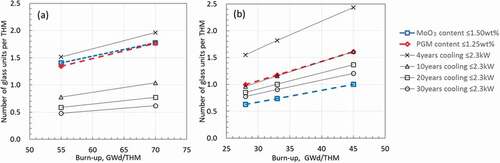
Figure 6. Number of glass units per GWd with respect to restriction factors of waste loading of waste glass and effects of cooling period of spent fuel; (a) UO2 fuel, (b) MOX fuel.
3.3. Storage period of waste glass for geological disposal
The evolution of heat generation rate of waste glass generated after 4 years cooling period of spent fuel is shown in . It is found that the effects of higher burn-up on heat generation rate of waste glass is negligibly small. In the case of 4 years cooling period of spent fuel, the storage periods prior to geological disposal when heat generation rate reaches to 0.35 kW/glass unit, which value is evaluated in the previous report [Citation11], are needed for approximately 50 years on UO2 fuel, and 80 years on MOX fuel.
Figure 7. Evolution of heat generation rate of waste glass with 4 years cooling period of spent fuel; (a) UO2 fuel, (b) MOX fuel.
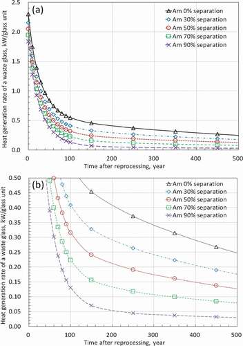
shows the evolution of heat generation rate of waste glass with higher waste loading in the case of extended cooling period of spent fuel. Restriction factors for determination of waste loading are MoO3 content for waste glass from UO2 spent fuel, and PGM content for waste glass from MOX spent fuel. The heat generation rate of a waste glass from UO2 spent fuel decreases to 0.35 kW/glass unit for approximately 50 years in spite of various cooling period, but waste glass from MOX spent fuel has large heat generation rate for long-term because of heat generation of minor actinides as shown in . There are mainly two approaches to decrease the heat generation rate; reduction of waste loading, separation of minor actinides. In order to evaluate the contribution of minor actinides for heat generation rate of waste glass from MOX spent fuel, the heat generation rate of waste glass caused by minor actinides in the case of 10 years cooling period of MOX spent fuel with burn-up of 45 GWd/THM is shown in . The decay heat of 241Am and 244Cm are dominant in the initial period after reprocessing. After some decades passed, heat contribution of 241Am become a dominant in the case of disposal of a vitrified waste form because of its large inventory and the long half-life. Therefore, it is expected remarkable reduction of heat generation rate of a waste glass from MOX spent fuel, if americium is separated from HLLW generated by MOX fuel reprocessing. shows the heat generation rate of waste glass from MOX spent fuel with Am separation at the burn-up of 45GWd/THM and cooling period of 10 years. shows properties and approximate storage period of waste glass from MOX spent fuel influenced by Am separation. The restriction factors to determine waste loading are PGM content except for the case of burn-up of 45GWd/THM, 10 years cooling period of MOX spent fuel, and without Am separation. The waste loading of waste glass in the case of 30% and 90% Am separation for the 10 years cooling period of MOX spent fuel are 19.10 and 18.15 wt%, respectively. The difference of waste loading is from the amount of extracted Am. Moreover, in the case of 30 years cooling period, the Am separation was more efficient on heat reduction than the case of shorter cooling period because amount of 241Am was increased by beta decay of 241Pu as shown in . Thus, Am separation can greatly shorten the storage period reaches to 0.35kW/glass unit. For instance, if 90% of Am was separated from HLLW, the heat generation rate of waste glass can be decreased below 0.35kW/glass unit for about 50 years.
Table 3. Effects of Am separation on heat generation rate and storage period before disposal for waste glass from MOX spent fuel with burn-up of 45GWd/THM
Figure 8. Effects of extended cooling period on evolution of heat generation rate of waste glass; (a) UO2 fuel with burn-up of 70GWd/THM, (b) MOX fuel with burn-up of 45GWd/THM.
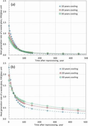
Figure 9. Contribution of minor actinides on heat generation rate of waste glass (MOX fuel, Burn-up; 45GWd/THM, Cooling period of spent fuel; 10 years).
Figure 10. Evolution of heat generation rate of waste glass as a function of Am separation ratio; (a) overall figure, (b) enlarged figure (MOX fuel, Burn-up; 45GWd/THM, Cooling period of spent fuel; 10 years).
3.4. Thermal analysis of near-field in geological repository
The evolution of heat generation rate in various scenarios were discussed so far. Especially, the storage period when heat generation rate of a waste glass reach to 0.35kW were evaluated because its heat generation rate can be used as an index whether its vitrified waste form can be disposed with minimum occupied area of 44.4 m2 in the vertical emplacement method. At this subsection, heat transfer calculations were conducted with the heat generation rate of waste glass in order to evaluate the maximum temperature of buffer material within 1,000 years after the emplacement of vitrified waste forms in the repository.
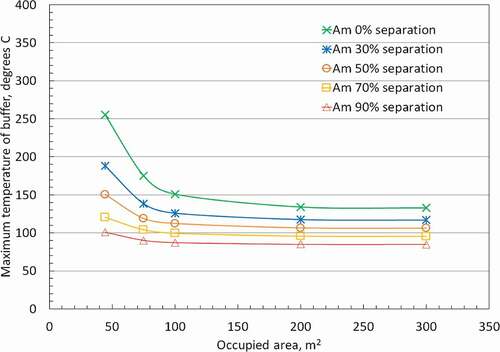
, , and show the relationships between maximum buffer temperature and occupied area. It confirmed that maximum temperature of buffer material is reached within 1000 years after disposal of vitrified waste forms in all cases. From , maximum temperature of buffer materials for the waste glass from UO2 spent fuel with burn-up of 70GWd/THM and 10 years cooling period of spent fuel cannot meet the heat restriction of buffer material of 100°C at minimum occupied area, though other case of cooling period meet the heat restriction. This is due to the effect of higher waste loading in waste glass comparing to the case of 4 years cooling period of spent fuel. Even if the cooling period is extended to 20 ~ 30 years, the waste loading is not appreciably increased because of the restriction of MoO3 content. Therefore, the case of 20 years and 30 years cooling period can meet the heat restriction at minimum occupied area of 44.4m2. From , which shows the case of the waste glass from MOX spent fuel with burn-up of 45GWd/THM, the heat generation rate of the waste glass from MOX spent fuel with over 10 years cooling period of spent fuel cannot meet the heat restriction because of larger heat generation rate as shown in () induced by higher waste loading (). In the case of waste glass from MOX spent fuel with 4 years cooling period, 115 m2 of occupied area is required to meet the heat regulation. Finally, the effects of Am separation on reduction of occupied area for disposal of waste glass from MOX spent fuel with higher waste loading is given in . These results show that 70–90% of Am separation is effective to reduce the heat generation of waste glass and occupied area.
Figure 11. Relationship between the maximum temperature of buffer material and occupied area per waste package corresponding to (a) and 8 (a) (UO2 fuel, Burn-up; 70GWd/THM).
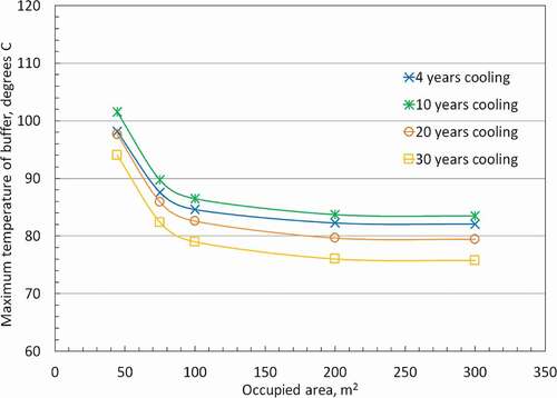
Figure 12. Relationship between the maximum temperature of buffer material and occupied area per waste package corresponding to (b) and 8 (b) (MOX fuel, Burn-up; 45GWd/THM).
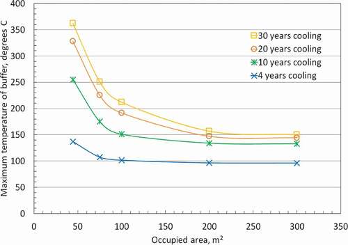
Figure 13. Relationship between the maximum temperature of buffer material and occupied area per waste package corresponding to (MOX fuel, Burn-up; 45GWd/THM, Cooling period of spent fuel; 10 years, Am separation is applied).
4. Conclusion
The properties of both UO2 and MOX spent fuels with various burn-up ratio were evaluated over 100 years since fuel discharge from a reactor to assess the effects of extended cooling period of spent fuel on the waste glass. As the results, not only the decay of short-lived radionuclides but also 241Am production by beta decay of 241Pu induced that heat generation rate of the waste glass is not decreased for a long time.
Then, the effects of extended cooling period of spent fuel on waste loading of waste glass were studied with respect to three restriction factors, that is heat generation rate, MoO3 content, and PGM content in waste glass. The results showed that waste loading was restricted by heat generation rate in the case of 4 years cooling period of spent fuel. In the case of extended cooling period over 10 years, however, limiting factor was shifted to MoO3 content for UO2 fuel and PGM content for MOX fuel. Therefore, even if heat generation rate of waste glass decrease caused by long-term cooling period, the waste loading does not appreciably increase.
In addition, the storage period of waste glass prior to geological disposal were assessed in consideration with effects of high burn-up and extended cooling period of spent fuel. In the case of 4 years cooling period, the periods that heat generation rate reaches to 0.35kW are approximately 50 years for UO2 fuel, and 80 years for MOX fuel. When the cooling period of spent fuel is extended for 10–30 years, the heat generation rate of the waste glass from UO2 spent fuel decreases to 0.35 kW/glass unit in 50 years, on the other hand the waste glass from MOX spent fuel has large heat generation rate for long-term because of significant contribution of 241Am. Then, the effects of Am separation of various separation ratios on storage period of the waste glass from MOX spent fuel were studied. It is concluded that 70–90% of Am separation is very effective to reduce the heat generation rate of waste glass.
Finally, heat transfer calculations were carried out with the heat generation rate of waste glass in order to evaluate the maximum temperature of buffer material. For the disposal of vitrified waste forms arisen from UO2 spent fuel with high burn-up of 70GWd/THM, it can meet the heat restriction of buffer material of 100°C at minimum occupied area of 44.4 m2 except for the case of 10 years cooling of UO2 spent fuel. Therefore, when waste loading is increased due to extension of cooling period, extension of storage period of waste glass or larger occupied area is one of the solution for disposal. In the case of waste glass from MOX spent fuel with burn-up of 45GWd/THM with 4 years cooling period, 115 m2 of occupied area is required to meet the heat regulation. There are three approaches to reduce the occupied area as a countermeasure for it; extension of storage period of waste glass, reduce of waste loading and separation of heat-generating nuclides. Therefore, the effects of Am separation on reduction of occupied area, which is as representative of heat-generating nuclides in a waste glass from MOX spent fuel, is evaluated. The results show that the 70–90% of Am separation is effective to meet the heat restriction of buffer material of 100°C.
These results indicate that it is essential to evaluate properties of waste glass in consideration with various scenarios such as higher waste loading, extension of cooling period of spent fuel, MOX fuel use, and partitioning for further nuclear energy utilization.
Supplemental Material
Download Zip (551.5 KB)Acknowledgement
A part of result in this study was obtained in RWMC‘s own research program entitled, ‘Study on the effects of advanced nuclear fuel cycle technology to the geological disposal concept’.
4. Disclosure statement
No potential conflict of interest was reported by the authors.
Supplementary material
Supplementary material can be accessed here.This article was originally published with errors. This version has been amended. Please see Erratum (http://dx.doi.org/10.1080/00223131.2018.1503409).
Related Research Data
References
- Oigawa H, Yokoo T, Nishihara K, et al. Parametric survey for benefit of partitioning and transmutation technology in terms of high-level radioactive waste disposal. J Nucl Sci Technol. 2007;44:398–404.
- Liang F, Liu X. Analysis on the characteristics of geologic disposal waste arising from various partitioning and conditioning options. Ann Nucl Energy. 2015;85:371–379.
- Stauff NE, Kim TK, Taiwo TA. Variations in nuclear waste management performance of various fuel-cycle options. J Nucl Sci Technol. 2015;52:1058–1073.
- Inagaki Y, Iwasaki T, Sato S, et al. LWR high burn-up operation and MOX introduction; fuel cycle performance from the viewpoint of waste management. J Nucl Sci Technol. 2009;46:677–689.
- Andra. Dossier 2005 argile – architecture and management of a geological disposal system. France: ANDRA; 2005, Report no.C.RP.ADP.04.0001.
- Bowman SM, Leal LC. ORIGEN-ARP: automatic rapid processing for spent fuel depletion, decay, and source term analysis. United States: Oak Ridge National Laboratory; 2004, Report no. NUREG/CR-0200.
- Ludwig SB. Standard- and extended-burnup PWR and BWR reactor models for the ORIGEN2 computer code. United States: Tenn. Oak Ridge National Laboratory; 1989.
- ASTM C996-96. Standard specification for uranium hexafluoride enriched to less than 5% 235U1. United States: ASTM International; 1996.
- Ishihara Y, Makino H, Ohi T, et al. Inventory evaluation of high level radioactive vitrified waste. Japan: Japan Nuclear Cycle Development Institute; 1999, Report no. TN8400 99-085 [in Japanese].
- Japan Nuclear Cycle Development Institute. Second progress report on research and development for the geological disposal of HLW in Japan; H12 project to establish the scientific and technical basis for HLW disposal in Japan, Supporting report 3: safety assessment of the geological disposal system. Japan: Japan Nuclear Cycle Development Institute; 2000, Report no. JNC TN1410 2000-004.
- Japan Nuclear Cycle Development Institute. Second progress report on research and development for the geological disposal of HLW in Japan; H12 project to establish the scientific and technical basis for HLW disposal in Japan, Supporting Report 2: Repository design and engineering technology. Japan: Japan Nuclear Cycle Development Institute; 2000. Report no. JNC TN1410 2000-003.
- Kawamura K, Ohuchi J. Characterization of highly waste loaded glass for HLW. Mat Res Soc Symp Proc. 1995;353:87–93.
- Igarashi H, Kawamura K, Takahashi T. Effects of noble metal elements on viscosity and electrical resistivity of simulated vitrified products for high-level liquid waste. Mat Res Soc Symp Proc. 1992;257:169–176.
- COMSOL. COMSOL multiphysics 5.2a, heat transfer module. Stockholm: COMSOL AB; 2016.
- The Japan Society of Mechanical Engineers. JSME data book: heat transfer. 5th ed. Tokyo: Maruzen; 2009.
- Japan Atomic Energy Agency. Improvement of the advanced geological disposal concept and performance assessment technology. Japan; 2013. in Japanese.
- The Japan Radioisotope Association. Radioisotope pocket data book. 11th ed. Tokyo: Maruzen; 2011.