
 ?Mathematical formulae have been encoded as MathML and are displayed in this HTML version using MathJax in order to improve their display. Uncheck the box to turn MathJax off. This feature requires Javascript. Click on a formula to zoom.
ABSTRACT
To reduce environmental burden and threat of nuclear proliferation, multi-recycling fuel cycle with high temperature gas-cooled reactor has been investigated. Those problems are solved by incinerating trans-uranium (TRU) nuclides, which is composed of plutonium and minor actinoid, and there is concept to realize TRU incineration by multi-recycling with fast breeder reactor. In this study, multi-recycling is realized even with a thermal reactor by feeding fissile uranium from outside of the fuel cycle instead of breeding fissile nuclide. In this fuel cycle, recovered uranium and natural uranium are enriched and mixed with recovered TRU to fabricate fresh fuels.
The fuel cycle was designed for a gas turbine high temperature reactor (GTHTR300). Reprocessing is assumed as existing reprocessing with four-group partitioning technology.
As a result, the TRU nuclides excluding neptunium can be recycled by the proposed cycle. The duration of potential toxicity decaying to natural uranium level can be reduced to approximately 300 years, and the footprint of repository for high-level waste can be reduced by 99.7% compared with the standard case. Surplus plutonium is not generated by this cycle. Moreover, incineration of TRU from light water reactor cycle can be performed in this cycle.
1. Introduction
High temperature gas-cooled reactor (HTGR) has attracted considerable attention from the viewpoint of safety [Citation1], especially in the light of the Fukushima Daiichi nuclear power plant disaster in Japan in 2011. In other words, HTGR is expected to server as a safe source of electric power that will play a major role in the nuclear fuel cycle. The safety of this reactor can be ascribed to the use of graphite in its core structure. Owing to the excellent thermal conductivity of graphite, heat from the core is removed safely, even in the event of an accident. However, the reactor type would inevitably be thermal neutron reactor because the graphite structure serves the role of moderator as well. It is said that fast breeder reactors (FBRs) have the advantages of transmutation of trans uranium (TRU) nuclides owing to excellent neutron economy. Moreover, multi-recycling, which was introduced to realize sustainable energy supply by means of breeding, should be employed to perform TRU transmutation. To perform multi-recycling, the fissile material should be retained to the next cycle by breeding against the consumption by burn-up.
However, with a thermal reactor, multi-recycling may be performed by feeding fissile uranium from out of the fuel cycle instead of breeding it. In addition, TRU nuclides consist of plutonium and minor actinoids (MAs). Surplus plutonium is problematic from the viewpoint of nuclear proliferation. MA is problematic from the viewpoint of environmental burden. In this context, we propose TRU multi-recycling with HTGR by feeding fissile uranium to solve these problems.
Therefore, we investigate the fuel cycle using by HTGR and design the cycle and the HTGR core to solve the problems related to TRU. Section 2 summarizes the problems related to TRU and TRU incineration to clarify the objectives of the proposed fuel cycle. Section 3 describes the concept of the proposed fuel cycle and calculation method. Finally, the calculation results and a discussion are given in Section 4.
2. Problems related to TRU and incineration
2.1. Problems related to TRU
The risk of plutonium proliferation needs no introduction. By contrast, the environmental burden of MAs, whose is posed by for plutonium as well, is very complex. In general, it is said that there are three problems, namely, public dose, potential toxicity, and volume and repository footprint of radioactive waste.
First, public dose is evaluated by radioactive nuclide migration calculation or the so-called groundwater model. Assuming corrosion of waste package and leakage of radioactive nuclides via groundwater, the inner and outer exposure to the public is evaluated. The dose must be lower than the guideline, which is set to approximately 1/10 of natural exposure. Public doses have been evaluated for high-level radioactive waste (HLW), including MAs [Citation2], and transuranic waste (TRU-waste) categorized as low-level radioactive waste [Citation3]. The safety has already been assessed. Those satisfy the guidelines with a large margin. MAs contribute the dose from the HLW, where neptunium and the daughter of 229Th, strictly speaking actinides in 4N + 1 decay series, have the largest contributions among in actinides. However, this contribution is negligible compared with that of 135Cs, which shows the largest dose peak. Moreover, the 135Cs dose is also negligible compared to the value prescribed in the guidelines because it is fives order of magnitude smaller. MAs, including neptunium, do not contribute significantly to public dose.
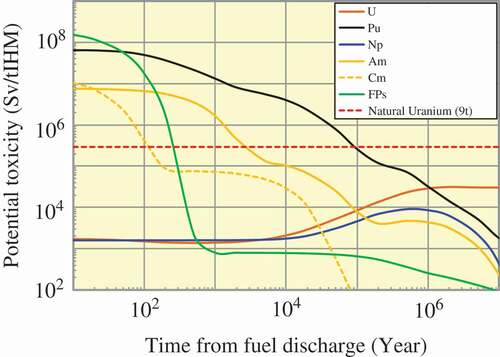
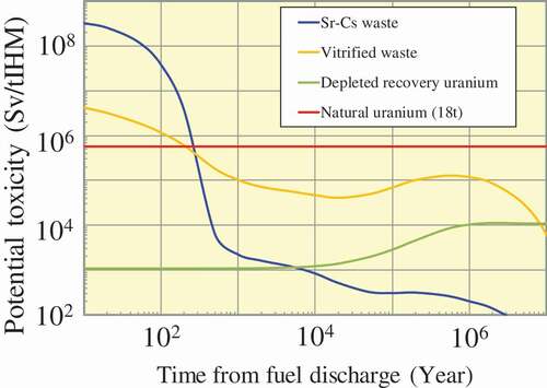
Second, potential toxicity is often used to show the effect of nuclear transmutation. Potential toxicity is defined as the total dose in the event of intake of whole radioactive nuclides. In Japan, the policy of geological disposal of HLW was criticized by the Science Council of Japan (SCJ), which was selected by Japan Atomic Energy Committee as a third-party source of opinion about HLW disposal. The opinions of the SCJ were distilled in a report entitled ‘Issues concerning HLW Disposal (Reply)’ [Citation4] in 2012. This report caused a fad of fearing potential toxicity among the public. An expert committee of Atomic Energy Society in Japan criticized this public tendency in their report [Citation5]. In their report, the expert committee emphasized that potential toxicity cannot be the index directly to assess safety, and the safety of geological disposal should be assessed based on public dose. In addition, they stated their own view that the safety of geological disposal tends to be assessed by potential toxicity in recent times because this indicator is intuitive. Potential toxicity has been recognized in public without depending on reasonability. However, not all MAs are problematic from the potential toxicity perspective. shows the potential toxicity of each element included in the spent fuels (SFs) of light water reactor (LWR). The toxicity of SFs should be lower than that of natural uranium used to fabricate the fuel. From the viewpoint of potential toxicity, neptunium, which accounts for approximately half the MAs, is not problematic in the first place.
Figure 1. Potential toxicity of each element in LWR SFs.
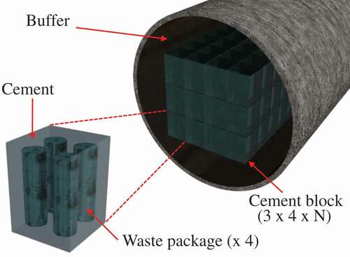
Third point is reduction of waste volume and its footprint (see also Appendix). MA recycling cannot reduce the volume of waste because the decay heat in which fission products (FPs) dominate determines the number of vitrified wastes in existing LWR reprocessing and vitrified technology. With four-group partitioning technology [Citation6], the number of waste packages can be reduced by approximately 60%. By contrast, in the case of MA recycling, the number of waste packages increases slightly because of additional wastes from MA recycling [Citation7]. The effect of the reduction in footprint depends on the scenario and disposal method because the decay heat is concentrated in Sr–Cs calcined waste and is not transmuted. The double-strata transmutation system concept [Citation8] employs compact emplacement, as shown in , with a cooling times of 45 and 320 years for vitrified waste and Sr–Cs calcined waste, respectively. The disposal realizes significant reduction of the footprint to 1/100 of the footprint achieved with the existing disposal plan. This is a major reason to promote this disposal plan. Only the decay heat from 241Am, whose half-life is 432 years, is problematic in the disposal, and necessary to be transmuted. Decay heat from other MAs is not problematic because the 18-year half-life of 244Cm is too short, which means it decays rapidly, and the 2.14-million-year half-life of 237Np is too long, which means that it releases decay heat at a very slow rate. In addition, in the scenario with 150 years cooling time and ordinary waste emplacement, MA recycling is not effective to reduce the footprint [Citation9].
Figure 2. Compact emplacement in geological disposal.
Consequently, we conclude the neptunium is not problematic from the environmental burden perspective.
2.2. TRU incineration with HTGR
Several plutonium incineration reactor concepts have been proposed, for example, concepts with HTGR, GT-MHR [Citation10], and deep burn [Citation11]. We proposed the concept of clean burn [Citation12] and have experience of designing the GTHTR300C MOX core [Citation13], which is a MOX-fueled reactor that is fed plutonium from an FBR. These concepts were designed based on a uranium-fueled reactor core, and the difficulties are found from the core design change.
The main difference is the large cross sections of plutonium compared with those of uranium. The difference is significant for HTGR, whose moderation power is lower than that of LWR. Especially, 240Pu has a large resonance absorption cross-section peak at 1.054 eV. This peak strengthens the temperature reactivity defect and the excess reactivity corresponding to the reactivity defect at cold zero power.
To incinerate the plutonium recovered from LWRs, which includes 20–30 wt% of 240Pu, the fuel region area should be increased, for example, as in deep burn and clean burn or the fuel inventory should be reduced to enhance neutron moderation. Even with the extended fuel region, the amount of fuel is limited by the larger cross section of plutonium. Therefore, the cycle length is shorter than 1 year.
In the GTHTR300C MOX design, two types of plutonium are fed from the FBR core, namely, multi-recycling plutonium extracted from the MOX part and discharged blanket plutonium. The composition of the multi-recycled plutonium is similar to that of the plutonium recovered from LWR. The discharged blanket plutonium is weapons-grade plutonium, composed mainly of 239Pu. The GTHTR300C MOX employs discharged blanket plutonium in almost all part of the MOX fuel to avoid 240Pu loading. Owing to this treatment, GTHTR300C MOX retains the same core configuration as that of the GTHTR300 [Citation14] uranium-fueled core. Even with the weapons-grade FBR blanket plutonium, the cycle length is 450 days, which is shorter than that of the uranium-fueled core, which is 730 days [Citation14]. The short cycle length reduces the load factor and worsens the economics of electricity power generation. In addition, GT-MHR, which employs plutonium oxide fuel with weapons-grade plutonium, needs erbium to attain a negative power reactivity coefficient. Moreover, plutonium reactors tend to have large control rods worth in dollar unit owing to the small delayed neutron fraction of around 0.2%, which is assumed to originate from 239Pu and 1/3 of 235Us. Consequently, the plutonium burner HTGR is inferior to the uranium-fueled HTGR from the safety, utility, and economic perspectives.
However, the uranium-fueled reactor also burns the plutonium generated from fresh fuel composed only of uranium. To prevent an increase in the amount of plutonium, the equilibrium amount of plutonium should be loaded in fresh fuels in the first place. More amount plutonium loading reduces the plutonium.
Here, to simplify the problem, we reduce the change in fissile amount as follows:
where Nfissile is the number density of a fissile nuclide (cm−3), Nfertile is the number density of a fertile nuclide (cm−3), is the microscopic cross section of neutron capture reaction for fertile nuclide (cm2),
is the microscopic cross section of neutron absorption reaction for fissile nuclide (cm2),
is the neutron flux (cm−2 s−1).
Here, we assume that the number density of fertile nuclides is constant. The assumption is reasonable because fertile nuclides are abundant, and the reduction is negligible in general reactor design. The asymptotic solution is as follows:
is the number density of a fissile nuclide in an equilibrium state (cm−3).
The plutonium fissile (Puf) fraction is evaluated as follows:
The relationship is shown in . With fast neutron, Puf fraction to whole actinoids is high at around 10%. On the contrary, the Puf fraction in a thermal reactor is very small, less than 1%. With the cross sections of 238U and 239Pu, the Puf fraction is approximately 0.6% in the GTHTR300 condition. It is said that the equilibrium inventory of MA is small for FBR because of the threshold fission reaction, and vice versa for thermal reactor. However, TRU recycling with realistic plutonium and MA amount would be feasible for the thermal reactor because of the smaller equilibrium amount of 239Pu, which is the source of higher MAs.
Figure 3. Relationship of equilibrium fissile fraction and cross sections.
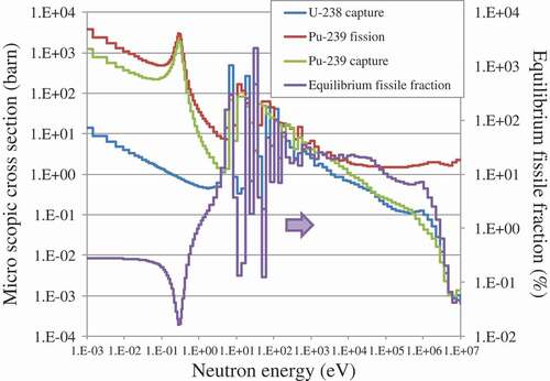
Moreover, GTHTR300 uses 14 wt% enriched uranium fuels. The neutronic characteristics are dominated by the fission of 235U even though a small amount of Puf obtained by multi-recycling is mixed in the fresh fuel. GTHTR300 can burn plutonium while retaining the original characteristics.
3. Concept of proposed fuel cycle and calculation method
3.1. Concept of proposed fuel cycle
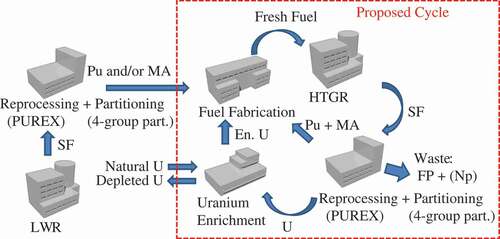
We propose a uranium-based TRU multi-recycling system with HTGR. The concept is shown in . In the fuel fabrication facility, enriched uranium, recovered plutonium, and MA from reprocessing and partitioning facility are mixed and used as fuel material. In the uranium enrichment facility, natural uranium and recovered uranium are enriched. The fabricated fuel is burned in HTGR. The SFs are reprocessed and partitioned in the reprocessing and partitioning facility, in which the existing PUREX technology [Citation15] and the demonstrated four-group partitioning technology [Citation6] are employed. Plutonium, uranium, and each MA are separated by the process. However, the plutonium must be mixed with the same amount of uranium according to the Japan–US reprocessing negotiation. From the outside of the fuel cycle, natural uranium and TRU nuclides recovered from LWR, which is optional, are provided. The neptunium generated in the proposed cycle and that generated in the LWR cycle is aggressively disposed of to establish the proposed cycle according to the calculation result in Section 4.1.
Figure 4. Proposed fuel cycle and material flow.
Here, we assume four schemes for this fuel cycle.
Basic TRU multi-recycling cycle
Only natural uranium is provided from outside of fuel cycle, and TRU nuclides excluding neptunium are recycled.
LWR plutonium incineration cycle
In this scheme, plutonium recovered from LWR is incinerated in the HTGR fuel cycle based on scheme 1.
LWR MA incineration cycle
In this scheme, MA recovered from LWR is incinerated in the HTGR fuel cycle based on scheme 1.
LWR TRU incineration cycle
In this scheme, TRU recovered from LWR is incinerated in the HTGR fuel cycle based on scheme 1. The TRU composition is the same as that obtained from the reprocessing and partitioning facility.
shows the lead and lag times, as well as the loss ratio of this cycle. These are determined by referring to reports of studies on the fuel cycle of HTGR [Citation16]. The loss ratio in the reprocessing and partitioning facility is 0.1%, which includes fabrication loss, and this loss value is the target of FBR fuel cycle as well [Citation17] from the viewpoint of reducing the potential toxicity of HLW, and it is employed because it is one of the objectives of the proposed cycle. According to the condition, each scheme is assessed.
Figure 5. Lead and lag times and loss ratio of proposed cycle.
3.2. Specifications of GTHTR300
The main specifications [Citation18] of GTHTR300 are listed in . GTHTR300 is a commercial-scale HTGR design with a 600-MW thermal power output. Its annular core, which comprises two batches of fuel blocks, is packed with 14 wt% enriched uranium fuel. The cycle length is 730 days.
Table 1. Main specifications of GTHTR300
The core configuration is shown in . The fuel columns are composed of eight fuel block layers aligned axially. Each fuel block is approximately 1 m high, yielding an approximate core height of 8 m. Because of the axial arrangement of the GTHTR300 core parts, axial fuel reloading is assumed. As the loading pattern for GTHTR300 design, Japan Atomic Energy Agency (JAEA) devised and implemented a method called sandwich refueling [Citation14]. The fuel blocks are divided into irradiated and fresh fuel batches. The irradiated fuel blocks are sandwiched between the fresh fuel blocks as shown in . The specifications of the fuel and the blocks are listed in , and those of the coated fuel particles (CFPs) are listed in . In addition, the uranium inventory is reduced slightly from the original 7.09 t [Citation18], because the fuel structure was revised from the viewpoint of fuel fabrication [Citation19]. The target cycle length and the average discharged burn-up are 730 days and 120 GW d/t, respectively.
Table 2. Specifications of fuel and blocks of GTHTR300
Table 3. Specifications of CFP of GTHTR300
Figure 6. Core geometry of GTHTR300.
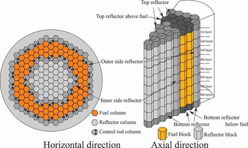
Figure 7. Sandwich refueling scheme.
3.3. TRU composition recovered from LWR SF
The specifications of TRU incineration depend on the TRU composition. The composition is assumed as that recovered from a pressurized water reactor (PWR), and it is evaluated using the ORIGEN [Citation20] code with the PWR47J40 library in ORLIBJ40 [Citation21], as described in Section 3.4.2. For the burn-up condition, the uranium enrichment of the fuel is 4.5 wt%. The discharge burn-up is 45 GW d/t with the specific power of 38.0 MW/t. The SF is reprocessed 4 years after discharge, and the separated TRU is used for fuel fabrication 2 years after reprocessing. The TRU composition is listed in .
Table 4. TRU composition from LWR SF (wt%)
3.4. Calculation method
3.4.1 Calculation of multi-component enrichment with cascade design
In the proposed cycle, recovery uranium is enriched and recycled. Uranium isotopes except for 235U and 238U are important as well. 236U would be accumulated and affect criticality; other components are released as depleted uranium to the environment, and they might have significant toxicity. To assess the feasibility of this cycle, a method for evaluating multi-component of uranium enrichment is necessary.
In general, to evaluate multi-component separation, the matched abundance ratio cascade theory, an extension of the ideal cascade theory of two components, is employed to match the abundance ratio at each feed point in the cascade [Citation22]. The abundance ratio is determined as ratio of the mole number of the target to that of a key component. In general, 238U is selected as the key component. In a two-component system, the target component is 235U, and the key component is 238U. By reducing the problem with each target component and the common key component, the two-component theory is extended as the multi-component theory. The targets would be 232U, 233U, 234U, 235U, 236U, and so on.
Yamamoto proposed a simple calculation method based on the matched abundance ratio cascade theory by exploiting the fact that each head and tail separation factor, namely α and β, respectively, is symmetrical for each target of the key component [Citation23], and this method is used in the present. This method needs feed condition, separation factor of each target nuclide from 238U, and cascade configuration as inputs. The cascade configuration is composed of number of stages n and stage number of feed f, as shown in . This method calculates the composition and flow rate of the product and the waste. Total flow rate of the cascade is calculated as well. For example, product composition can be calculated using the obtained total cuts as follows:
Figure 8. Schematic diagram of uranium enrichment cascade.
where is the mole fraction of ith isotope in product flow (–),
is the mole fraction of ith isotope in feed flow (–),
is the total cut of ith isotope (–).
The separation factor is evaluated by assuming gas centrifuges [Citation15] as follows,
where is the separation factor of ith isotope (-),
is the molecular weight of key component (kg/mol),
is the molecular weight of ith isotope (kg/mol),
is the peripheral velocity of gas in centrifuges (m/s), R is the gas constant (8314.4 J/(kg mol K)), T is the gas temperature (K).
In this method, the operation condition and the cascade configuration are determined to realize a requested product enrichment. We assumed the peripheral velocity and gas temperature to be 400–600 m/s and 300 K, respectively. These are the general operation conditions of a gas centrifuge plant [Citation15]. The target enrichment is set to 19.9 wt%, which is in the range of low enriched uranium (LEU) and the highest value, to screen out 236U.
3.4.2 Calculation of core burn-up
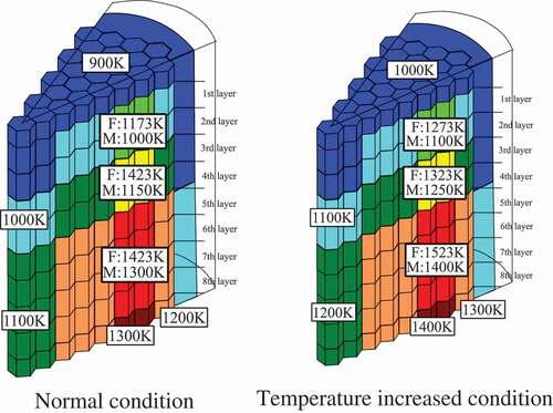
The burn-up characteristics are assessed using the core burn-up calculation implemented in the MVP [Citation24] code, a Monte Carlo neutron transport code that uses evaluated nuclear data of JENDL-4.0 [Citation25]. Moreover, the double heterogeneity of CFPs is analyzed directly by using a statistical geometric model [Citation26]. The MVP calculations were implemented in three-dimensional whole-core models. Each core is composed of two batches, as described in Section 3.2. To evaluate the equilibrium cycle core, the fuels were reloaded several times to obtain a saturated state according to the sandwich reloading scheme described in Section 3.2. To evaluate the temperature coefficient, the reactivities were compared with a reference state and an elevated temperature state (100 K increase for each region). The temperature condition is shown in . Moreover, in the present study, the effective delayed neutron yields were evaluated using the prompt method [Citation27] as follows:
Figure 9. Temperature condition for evaluating reactivity coefficient.
where is the effective delayed neutron fraction (–), k is the effective multiplication factor (–), kp is the effective multiplication factor with only prompt neutron fission (–).
In the prompt method, EquationEquation (6)(6)
(6) is obtained by reducing the definition of effective delayed neutrons obtained during the derivation of the point-kinetics equation without approximation. The accuracy was confirmed (Meulekamp et al., 2006).
3.4.3. Calculation of detailed fuel composition, decay heat, and radioactivity
To evaluate the fuel burn-up composition, ORIGEN code was used. ORIGEN can evaluate not only fuel burn-up composition but also decay heat and radioactivity. The composition changes with the lead and lag times, as described in Section 3.1, were calculated using ORIGEN as well. MVP can also calculate fuel burn-up composition, but it selects nuclides from the viewpoint of criticality, and the number of nuclides is inadequate for evaluating decay heat and radioactivity accurately. ORIGEN can calculate these parameters accurately by treating approximately 1400 nuclides. However, ORIGEN cannot evaluate the neutron spectrum in a core, and that uses one energy group cross-section libraries. For major reactors, libraries have already been developed. Japan Nuclear Data Committee has developed the ORIGEN library of ORLIBJ40 based on the evaluated nuclear data of JENDL-4.0. ORLIBJ40 includes libraries for LWRs and FBRs. However, libraries for HTGR do not exist.
A cross-section library for HTGR is developed in the present study. The scheme [Citation28] is as follows. ORIGEN libraries have two types of cross-section library: variable actinide cross-section (VAXS) library and static library. The VAXS library depends on burn-up and includes the cross sections of 20 nuclide-reactions of actinoid nuclides. The cross sections are taken from MVP. The MVP calculations are performed using JENDL-4.0. MVP provides effective cross sections for the static library as well. However, the effective cross sections provided by MVP for approximately 100 nuclides are insufficient for the static library, which includes the cross sections of approximately 1400 nuclides. Then, not only JENDL-4.0 but also JEFF-3.1.2 [Citation29], JENDL/A-96 [Citation30], JEFF-3.1/A [Citation31], and TENDL-2011 [Citation32] are used in order of descending priority. To treat these nuclides, infinite dilution cross sections with the 108 energy group structure are generated using the nuclear data-processing code NJOY [Citation33]. Thereafter, the cross section is condensed by the 108 energy group neutron spectrum provided in the MVP code. The cross sections and neutron flux from the MVP code at middle of cycle (MOC) are used in the static library. The geometry model used for the MVP calculation is the same as the entire core calculation described in Section 3.4.2. However, the calculation is performed considering a one-batch core to evaluate the burn-up characteristics from beginning of life (BOL) to end of life (EOL) when using the VAXS library. Owing to this treatment, the burn-up characteristics of HTGR are reflected in almost all nuclide data in the ORIGEN library.
3.4.4. Calculation of environmental burden
In the proposed cycle, we assume the use of partitioning technology, as described in Section 3.1. When using the partitioning technology, vitrified waste and Sr–Cs calcined waste are generated. The waste package specifications and fabrication limitations [Citation34] are listed in . Basically, the partitioning recovery ratio is assumed to be the value developed [Citation35]. However, only when evaluating potential toxicity, we assume that 0.1 wt% of actinoids with the same composition as that in reprocessing is mixed into the vitrified waste to consider the loss during fuel fabrication as well. Potential toxicity is defined as the ingestion dose resulting from the intake of when whole radioactive nuclides. To evaluate potential toxicity, the radioactivity evaluated in ORIGEN is converted into dose by using the dose coefficient tabled in ICRP Pub. 72 [Citation36], which is the dose coefficient for public inner exposure.
Table 5. Specifications of vitrified waste and Sr–Cs calcined waste forms, and limitations of fabrication process
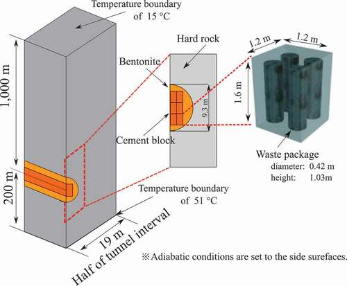
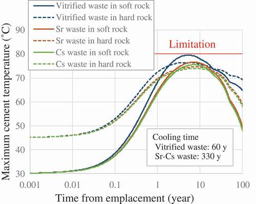
The repository footprint of the waste packages is evaluated by thermal calculation by using the decay heat obtained using the ORIGEN code. and show the thermal calculation model for the repository of compact emplacement for soft-rock repository [Citation3] and hard-rock repository [Citation33], respectively. The cement-based materials used to fill voids in the waste packages are assumed to deteriorate at temperatures higher than 80°C [Citation3]. The cement temperature of 80°C is the limitation of compact emplacement. The maximum cement temperature was evaluated by performing time-dependent thermal conductivity calculations in ANSYS [Citation37], which solves the thermal equation by using the finite-element method with an implicit time-integral technique.
Figure 10. Temperature calculation model for compact emplacement in soft rock.

Figure 11. Temperature calculation model for compact emplacement in hard rock.
4. Result and discussion
4.1. Comparison of specification between GTHTR300 and basic TRU multi-recycling core
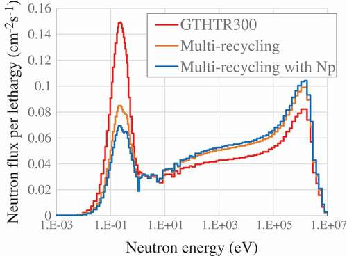
To elucidate the nuclear characteristics of the basic TRU multi-recycling core of scheme 1, the main specifications are compared with that of GTHTR300 in . To compensate for the reactivity defect due to TRU multi-recycling, the uranium enrichment was increased in the range of LEU. However, the enrichment cannot reach around 20 wt% because unenriched recovery uranium accompanies recovery plutonium according to the Japan–US reprocessing negotiation. With increasing uranium enrichment, a multi-recycling core with almost the same cycle length can be realized. On the contrary, the cycle length decreases significantly to less than 400 days (13 months: the shortest interval of periodic inspections in Japan) in the case of multi-recycling with neptunium. This reactor design is not acceptable from the viewpoint of utility. Therefore, neptunium is aggressively disposed of in the proposed fuel cycle. The reason for the reactivity defect is found from the neutron spectrum shift shown in . The spectrum is observed in the fuel kernel region of CFPs. A reactor core in multi-recycling with neptunium has the hardest spectrum. lists the fuel composition of each core. The equilibrium concentrations of 239Pu and converted nuclides increase along with the spectrum shift, and vice versa. For the case of multi-recycling with neptunium, the fuel includes neptunium and converted 238Pu. These components harden the spectrum and cause reactivity defects due to the neutron absorption reaction. The large amount of 236U around 10 wt% is characteristics of the multi-recycling core. This causes the reactivity defect as well.
Table 6. Comparison of main specifications of GTHTR300 and multi-recycling core
Table 7. Fuel composition of each core (wt% IHM)
Figure 12. Neutron spectrum of GTHTR300 and multi-recycling core in fuel region.
lists the excess reactivity at the beginning of cycle (BOC), which was evaluated in an equilibrium state of xenon and is equivalent to burn-up reactivity defect. The reactivity defect of multi-recycling core is less than half that of GTHTR300, even with the same degree of discharged burn-up because of increased uranium enrichment and converted Puf nuclides. The effective delayed neutron fractions are evaluated from BOC to end of cycle. Those of the multi-recycling core are as the same as those of GTHTR300, which is an ordinary uranium-fueled core, and they remain higher than 0.5% throughout the cycle. The fission fraction of each nuclide at MOC is listed in . Even though the fission fraction of 239Pu tends to increase, that of 235U accounts for more than 70% of the multi-recycling core because of the increased uranium enrichment. The temperature coefficient of reactivity of the multi-recycling core is superior to that of GTHTR300 because of the enhanced Doppler effect owing to increased neutron flux in the resonance energy region and increased TRU nuclides, which has a resonance peak of neutron capture cross section, such as 240Pu.
Table 8. Fission fraction of each nuclide at MOC (%)
Specifications of the cascade for enrichment of recovery uranium and the composition of feed, product, and waste are listed in and . The cascade and the operating parameters of the gas centrifuge plant were determined to obtain product enrichment of 19.9 wt% and waste enrichment around 0.2–0.3 wt%. The composition of 236U in waste is 10 times larger than that of 235U. This stands for the fact that the enrichment of recovery uranium excludes 236U from the cycle.
Table 9. Specifications of enrichment cascade for recovery uranium
Table 10. Composition of recovery uranium enrichment (wt%)
4.2. Comparison of specifications between each scheme of TRU multi-recycling core
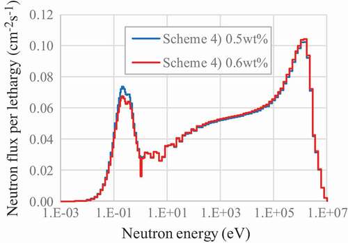
The main specifications of the core in each fuel cycle scheme are listed in . The feeding TRU inventory stands for the amount of TRU recovered from the LWR cycle supplied from outside of the HTGR fuel cycle by mixing with fresh fuel in addition to recovered TRU. This corresponds to the amount incinerated in one cycle. The specifications are shown for two cases with the two feeding TRU inventories to observe the changes in specification. The increased inventories significantly decrease the cycle lengths owing to the TRU cumulation and the hardened neutron spectrum as shown in –. The decreased cycle length also reduces the TRU incineration amount, which is proportional to the cycle length. This is why the sensitivity is significant. The decreased cycle length decreases the excess reactivity. The cumulated TRU slightly decreases the effective delayed neutron fraction, even though it remains around 0.5%. By contrast, the temperature coefficients are improved slightly. The compositions of the fresh and the discharged fuel are listed in and . By increasing the feeding TRU amount of 0.1 wt%, the equilibrium TRU amount increases by around 1.0 wt% in each case as discharged composition listed in .
Table 11. Comparison of main specifications of each scheme
Table 12. Composition of fresh fuel in each scheme (wt%IHM)
Table 13. Composition of discharged fuel in each scheme (wt% IHM)
Figure 13. Change on neutron spectrum by increased inventory for scheme 2.
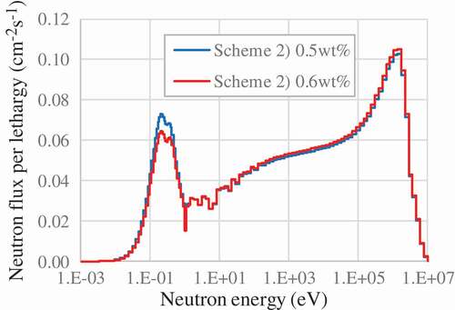
Figure 14. Change on neutron spectrum by increased inventory for scheme 3.

Figure 15. Change on neutron spectrum by increased inventory for scheme 4.
The relation can be evaluated as follows:
where ΔTRU is the increase of the amount of the cumulated TRU in discharged composition (–), ΔTRUfeed is the increase of the amount of the feed TRU (–), r is the residual ratio of the feed TRU per fuel cycle (–), CycleLength is the cycle length of reactor operation cycle (day),
ΔCycleLength is the change in cycle length of reactor operation cycle (day).
The increase of the amount of the cumulated TRU is defined as summation of the remained feed TRU without fission. That is evaluated as the sum of the infinite geometric series because the remained TRU would be incinerated again in the next cycle. The residual ratio can be commonly guessed by EquationEquation (7)(7)
(7) approximately 0.9. In addition, the increase of cumulated TRU amount of 1 wt% and the residual ratio approximately 0.9 means the incineration amount is enhanced for more 0.1 wt%, which is corresponding to 0.1 wt% of increased feed TRU.
lists the specifications of TRU incineration. These specifications were evaluated for the core with the cycle length of 400 days by interpolation and extrapolation of the results listed in . The ratio of electricity generation capacity of TRU incineration HTGR to that of LWR generating TRU is listed as well. It stands for the electricity generation capacity of the TRU incineration HTGR required to incinerate the TRU generated from LWR per unit electricity generation capacity. For LWR, an advanced pressurized water reactor with output of 1538 MWe is assumed. To correspond the electricity generation capacity, five units of HTGR (280 MWe/unit) are required. The ratio of schemes 2 and 4 is almost the same because the fraction of MA in TRU is small at around 10%, and it decreases further to 5% by excluding neptunium. To incinerate plutonium or TRU from LWR, approximately five times the electricity generation capacity of HTGR or time is necessary. On the contrary, by using scheme 3, MA from LWR, excluding neptunium, can be incinerated by using half the electricity capacity of HTGR.
Table 14. TRU incineration by core with cycle length of 400 days
4.3. Environmental burden of proposed TRU multi-recycling
The potential toxicity of radioactive waste from the proposed fuel cycle is shown in . It is represented by scheme 1. Unlike the double-strata transmutation system, the vitrified waste includes neptunium. In addition, the toxicity of the depleted uranium from the enrichment of recovery uranium is evaluated as well because this uranium accounts for 2.3 wt% of 236U, as listed in , unlike ordinary depleted uranium. Even with these differences, the cooling time required to decay the dose to levels lower than that of natural uranium is approximately 300 years, which is the same as that of the double-strata transmutation system.
Figure 16. Potential toxicity of proposed TRU multi-recycling scheme.
The number of waste packages generated per unit electricity generation is listed in . GTHTR300 [Citation38] and GTHTR300 with partitioning [Citation9] were evaluated in previous studies. By employing partitioning, the number of waste packages is reduced significantly, as described in Section 2.2. GTHTR300 with partitioning and multi-recycling, which employs the partitioning technology as well, does not show a significant difference because the number of waste packages generated mainly depends on the amount of FPs generated, which is proportional to the amount of electricity generated.
Table 15. Number of waste packages generated per unit electricity generation (#/TWeh)
To determine the repository footprint, the maximum temperature of the cement blocks is evaluated by thermal calculation. The result is shown in . As cooling times between reprocessing and disposal, 60 and 330 years are required, respectively, for vitrified waste and Sr–Cs calcined waste to satisfy the temperature limitation. The feasibility of compact emplacement is confirmed. The footprints of 0.76 m2/canister and 0.95 m2/canister can be realized, respectively, for the soft- and the hard-rock repositories. The footprint per unit electricity generation is summarized in . GTHTR300 [Citation38] and GTHTR300 with partitioning [Citation9] were evaluated in previous studies. The footprint of the soft-rock repository can be reduced by 99.7% (corresponding to 1/300 of existing disposal) by using the proposed TRU multi-recycling scheme with partitioning technology.
Table 16. Comparison of repository footprint per unit electricity generation
Figure 17. Maximum temperature of cement block after emplacement.
5. Conclusions
To reduce environmental burden and threat of nuclear proliferation, a multi-recycling fuel cycle with HTGR was proposed and investigated. The major results are described as follows:
To realize TRU multi-recycling, it is necessary that the thermal neutron reactor prevents hardening of the neutron spectrum and reduces the equilibrium concentration of TRUs. With HTGR, the fuel cycle is feasible by increasing uranium enrichment and aggressively disposing of neptunium. This fuel cycle does not emit plutonium and MAs except for neptunium.
Moreover, TRUs other than the neptunium recovered from the LWR cycle can be incinerated by adding them to the equilibrium cycle. When the fuel cycle is designed with cycle length of 400 days, only half of the electricity capacity of HTGR should be installed to incinerate the MAs generated by the LWR cycle. However, to incinerate plutonium, five times of the electricity capacity of HTGR or time is required.
We confirmed that the cooling time to decay the potential toxicity to levels lower than natural uranium level reduced to approximately 300 years with less than 0.1% loss in fuel fabrication and reprocessing.
The repository footprint was evaluated with partitioning technology. The footprint can be reduced by 99.7% (corresponding to 1/300 of the existing disposal) compared to existing technology in the case of the soft-rock repository by employing compact emplacement.
Acknowledgments
The authors appreciate Dr. J. Sumita of JAEA who is an expert in back end of HTGR. The authors also appreciate Mr. Y. Tanaka in Ningyo-toge Environmental Engineering Center of JAEA who is an expert in uranium enrichment and supports to develop the program of multi-component enrichment method.
Disclosure statement
No potential conflict of interest was reported by the authors.
References
- Ohashi H, Sato H, Tachibana Y, et al. Concept of an inherently-safe high temperature gas-cooled reactor. Proc ICANSE 2011. 2011 [2011 Nov. 14-17];Bali(Indonesia):50–58.
- Japan Nuclear Cycle Development Institute. Second Progress Report on Research and Development for the Geological Disposal of HLW in Japan; H12: project to Establish the Scientific and Technological Basis for HLW Disposal in Japan, Project Overview Report. Ibaraki: Japan Nuclear Cycle Development Institute; 2000, JNC TN1410 2000-001.
- Japan Atomic Energy Agency. Federation of Electric Power Companies. Second progress report on research and development for TRU waste disposal in Japan; Repository design, safety assessment and means of implementation in the generic phase. Ibaraki-ken: Japan Atomic Energy Agency; 2007, JAEA-Review 2007-010.
- Science Council of Japan. Issues concerning HLW Disposal (Reply). Science Council of Japan; 2012, [in Japanese]. [cited 2018 Mar 9]. Available from: http://www.scj.go.jp/ja/info/kohyo/pdf/kohyo-22-k159-1.pdf
- Atomic Energy Society of Japan. Interim report of expert committee on social environment concerning to direct disposal of spent fuel. Atomic Energy Society of Japan; 2014, [in Japanese]. [cited 2018 Mar 9]. Available from: http://www.aesj.net/document/com-r_shiyouzuminenryou2014_m.pdf
- Kubota M, Morita Y. Preliminary assessment on four group partitioning process developed in JAERI. Proc GLOBAL’97. 1997 Oct 5-10;Tokyo(Japan):458–462.
- Nishihara K, Nakayama S, Morita Y, et al. Impact of partitioning and transmutation on LWR high-level waste disposal. J Nucl Sci Technol. 2008 Jan;45(1):84–97.
- Oigawa H. Present status and prospect of transmutation technology for high-level radioactive waste. Radioisotopes. 2012;61:571–586. [in Japanese].
- Fukaya Y, Goto M, Ohashi H, et al. optimization of disposal method and scenario to reduce high level waste volume and repository footprint for HTGR. Annal Nucl Eng. 2018 Mar;116:224–234.
- Kodochigov N, Sukharev Y, Marova E, et al. Neutronic features of the GT-MHR reactor. Nucl Eng Des. 2003 Jun;222:161–171.
- Rodiriguez C, Baxter A, MacEachern D, et al. Deep-Burn: making nuclear waste transmutation practical. Nucl Eng Des. 2003 Jun;222:299–317.
- Fukaya Y, Goto M, Ohashi H, et al. Proposal of a plutonium burner system based on HTGR with high proliferation resistance. J Nucl Sci Technol. 2014 Apr;51(6):818–831.
- Mouri T, Nishihara T, Kunitomi K. Nuclear and thermal design for high temperature gas cooled reactor (GTHTR300C) using MOX fuel. Nihon-Genshiryoku-Gakkai Shi (J At Energy Soc Jpn.). 2007;6(3):253–261. [inJapanese].
- Yan X, Kunitomi K, Nakata K, et al. GTHTR300 design and development. Nucl Eng Des. 2003 Jun;222:247–262.
- Benedict M, Thomas HP, Hans WL. Nuclear Chemical Engineering. New York: Mcgraw-Hill Book Company; 1981.
- Takei M, Katanishi S, Nakata T, et al. Study on the fuel cycle cost of Gas Turbine High Temperature Reactor (GTHTR300) (Contract research). JAERI-Tech 2002-089. Ibaraki-ken: Japan Atomic Energy Research Institute, 2002.
- Advanced Nuclear System Research and Development Directorate, Research and Development Department, The Japan Atomic Power Company, Fast Reactor Cycle Technology Development Project (FaCT Project) -Phase I Report. Ibaraki-ken: Japan Atomic Energy Agency; 2011, JAEA-Evaluation 2011-003, [in Japanese].
- Nakata T, Katanishi S, Takada S, et al. Nuclear, thermal and hydraulic design for Gas Turbine High Temperature Reactor (GTHTR300). Nihon-Genshiryoku-Gakkai Shi (J At Energy Soc Jpn.). 2003;14(3):478–489. [in Japanese].
- Fukaya Y, Goto M, Nishihara T. Development on nuclear design model for detailed design of clean burn HTGR. JAEA-Technology 2015-017. Ibaraki-ken: Japan Atomic Energy Agency; 2015, [in Japanese].
- Croff AG. ORIGEN2: A versatile computer code for calculating the nuclide compositions and characteristics of nuclear material. Nucl Technol. 1983 Sep;62:335–352.
- Okumura K, Sugino K, Koshima K, et al. Set of ORIGEN2 cross section libraries based on JENDL-4.0; ORLIBJ40. JAEA-Data/Code 2012-032. Ibaraki-ken: Japan Atomic Energy Agency; 2012.
- Garza A, Garrett GA, Murphy JE. Multicomponent isotope separation in cascades. Chem Eng Sci. 1961 Sep;15(3–4):188–209.
- Yamamoto I, Kaba A, Kanagawa A. Simple formulae for analyzing matched abundance ratio cascade with constant separation factors for multi-component isotope separation. J Nucl Sci Technol. 1987 Nov;24(11):961–971.
- Nagaya Y, Okumura K, Mori T, et al. Carlo neutron/photon transport code MVP 2, Trans. Am Nucl Soc. 2006 Nov;95:662–663.
- Shibata K, Iwamoto O, Nakagawa T, et al. JENDL-4.0: a new library for nuclear science and technology. J Nucl Sci Technol. 2011 Jan;48:1–30.
- Murata I, Takahashi A, Mori T, et al. New sampling method on continuous energy Monte Carlo calculation for pebble bed reactors. J Nucl Sci Technol. 1997 Aug;34(8):734–744.
- Meulekamp R, Marck S. Calculating the effective delayed neutron fraction with Monte Calro. Nucl Sci Eng. 2006 Feb;152:142–148.
- Fukaya Y, Ueta S, Goto M, et al. Study on methodology to estimate isotope generation and depletion for core design of HTGR. JAEA-Research 2013-035. Ibaraki-ken: Japan Atomic Energy Agency; 2013, [in Japanese].
- Koning AJ, Bauge E, Dean CJ, et al. Status of the JEFF Nuclear Data Library. J Korean Phys Soc. 2011 Aug;59(2):1057–1062.
- Nakajima Y. JNDC WG on Activation Cross Section Data: “JENDL Activation Cross Section File”. Proceedings of the 1990 Symposium on Nuclear Data. JAERI-M 91-032, 43-57. Ibaraki-ken: Japan Atomic Energy Research Institute; 1991.
- Koning AJ, Forrest R, Kellett M, et al. The JEFF-3.1 Nuclear Data Library.JEFF Report 21. Paris: OECD Publishing; 2006.
- Koning AJ, Rochman D. TENDL-2011: TALYS-based Evaluated Nuclear Data Library: nuclear Research and consultancy Group. Petten: NRG; 2011. Available from: http://www.talys.eu/
- MacFrlane R, Kahler A. Method for Processing ENDF/B-VII with NJOY. Nucl. Data Sheets. 2010 Dec;111:2739–2890.
- Nishihara K, Oigawa H, Nakayama S, et al. Impact of partitioning and transmutation on high-level waste disposal for the fast breeder reactor fuel cycle. Nucl Sci Technol. 2010 Jun;47(12):1101–1117.
- Oigawa H, Yokoo T, Nishihara K, et al. Parametric survey on possible impact of partitioning and transmutation of high-level radioactive waste. Proc GLOBAL 2005. 2005 Oct 9-13; Tsukuba(Japan):#266. [CD-ROM].
- ICRP. ICRP Publication 72: age-dependent Doses to the Members of the Public from Intake of Radionuclides Part 5, Compilation of Ingestion and Inhalation Coefficients. Oxford: ICRP. Annals of the ICRP; 1996: 26.
- ANSYS, Inc. ANSYS Mechanical APDL Theory Reference. Canonsburg (PA): ANSYS, Inc.; 2013.
- Fukaya Y, Nishihara T. Reduction on high level radioactive waste volume and geological repository footprint with high burn-up and high thermal efficiency of HTGR. Nucl Eng Des. 2006 Jul;307:188–196.
Appendix.
Reduction of waste volume and footprint of HLW with partitioning technology
To use geological repositories effectively, the volume of waste, in other words, number of waste packages, and repository footprint per package should be reduced. With the existing reprocessing scheme, HLW packages are in the form of vitrified waste and contain waste nuclides, namely, FPs and MAs. The number of HLW packages is determined by the content. This number is limited not only by the amount of whole waste nuclides, but also decay heat, platinum group metals (PGMs), and other factors, as summarized in from the viewpoint of fabrication and storage of waste packages [Citation9]. To reduce the number of vitrified waste packages generated, these contents should be partitioned. Four-group partitioning technology [Citation6] was developed to this end. By using this technology, high-level liquid waste is processed and partitioned into four groups, namely, Sr–Cs group, PGM group, MA group, and others group. The Sr–Cs group is the major heat source among the waste nuclides, and it is disposed of in the form of Sr–Cs calcined waste. The PGM group is used as a resource. The MA group is recycled in the fuel cycle. The others group is formed in the vitrified waste. As a result, the number of vitrified waste packages is reduced significantly even with the number of Sr–Cs calcined waste.
The repository footprint is determined by the disposal method, integrity of repository, and decay heat from waste packages. To dispose of the waste packages, tunnels are dug into the host rock of the repository. The size of the tunnel is different for each disposal method. The footprint is defined as the area per waste package required in disposal by assuming an infinite system of repeated tunnels and disposed waste packages. Moreover, there is the limitation of temperature of the buffer material or concrete around the waste packages. To reduce footprint, the interval between the tunnels and/or waste packages should be reduced so long as the materials’ temperature does not exceed the limitation of decay heat. The intervals are also limited by repository integrity. A tunnel system with densely deployed tunnels and/or disposal holes would collapse.