
 ?Mathematical formulae have been encoded as MathML and are displayed in this HTML version using MathJax in order to improve their display. Uncheck the box to turn MathJax off. This feature requires Javascript. Click on a formula to zoom.
ABSTRACT
A novel scheme for a bilayer coating with self-healing ability is proposed in this study. The candidate materials for the coatings and the potential self-healing reaction are assessed in high-temperature aqueous environments and high-temperature air. The pure Cr2O3 layer and the composite of Cr2O3 and MoO3 are the candidate materials for the outer layer and inner layer, respectively, due to their compatibility under normal condition and fabricability. Fe2O3–MoO3 reactions exhibit a potential ability to heal the cracks because of a high reaction rate under normal condition. The self-healing process proceeds via the following mechanism under normal condition: Fe2O3 (a corrosion product in the coolant) diffuses into the cracks on the coating and reacts with MoO3 (inner layer) to produce the insoluble Fe2(MoO4)3, which deposits and repairs the cracks. In the loss-of-coolant accident (LOCA) situation, Cr2O3–MoO3 reaction is expected to strengthen the adhesion of the coating.
1. Introduction
Zirconium-based (Zr-based) alloys have been widely used as the materials for fuel cladding [Citation1]. Their mechanical properties and corrosion resistance have been improved significantly by optimization of the chemical composition and/or heat treatment, generating advanced Zr-based alloys such as M5®, ZIRLO™, J-alloys™, and so on [Citation2]. However, the inherent defects with Zr-based alloys, especially the Zr-steam reaction in the LOCA condition, are the largest threat to nuclear safety. After the Fukushima-Daiichi accident, more research has been devoted to search for substitute materials, like FeCrAl alloy [Citation3] and silicon carbide composite [Citation4], which are expected to tolerate a loss of active cooling for a longer time while maintaining or improving fuel performance. Also, some researchers are attempting to enhance the corrosion resistance of the current Zr-based cladding with coating technology, such as Cr [Citation5] and MAX-phase coatings [Citation6]. Compared with alternative materials, coating technology is much more economic and time-saving due to minor or no modifications of the base materials.
As a branch of coating technology, the self-healing coating is expected to provide much higher reliability and a wider safety margin for nuclear reactors. In our previous study [Citation7], cracks are the critical defects for the ceramic coating. As-received cracks (formed during the fabrication process) were also found in the MAX-phase coatings [Citation8] and even in the Cr coating [Citation9] although they were prepared by the different methods. In addition, microcracks may form during the transportation and installation due to the poor toughness of the ceramic coatings.
It was reported that α-Fe2O3 and Fe3O4 are the principal components of the CRUD (corrosion products of the core structural materials) in light water reactors (LWRs), and other minor compounds, like NiO, Cr2O3, and ZrO2, were also observed [Citation10].
The compounds, continuously fed through the LWR coolant water, may trigger additional reactions at the tip of cracks. These reactions can be called as self-healing. One of the candidates is the reaction of iron oxide with MoO3 to produce the insoluble molybdate compounds. The basis of this idea is to create a bilayer coating on the surface of cladding tubes. The outer layer must protect the inner layer from undesirable reactions with substances in the LWR water. Once a crack is introduced, the inner layer is exposed to the water and the self-healing reaction takes place. Based on this motivation, the purpose of this work is to survey the possible candidate substances for the outer and inner layers and to find the possible self-healing reaction under normal operating condition of LWR, as well as the accident condition at LOCA. In this work, they are set as 360 °C in pressurized pure water and as high temperature below 1000 °C in air, respectively. The required performance for the outer layer is to maintain the phase stability under normal and accident conditions. The requirement for the inner layer is to have reasonable reactions to produce insoluble substance under normal condition. Therefore, the coating is expected to increase the corrosion resistance and widen the safety margin of the fuel cladding.
2. Experimental
2.1. Specimens
As introduced above, CRUD mainly consists of metal oxides. In the high-temperature aqueous environment, the hydroxides may be the precursors of these oxides. Thus, investigations on the hydration-to-oxide transformation as well as the possibility of hydroxide–MoO3 reactions are necessary. Oxides and hydroxides were taken into consideration in this study. Pure powders, such as MoO3 (99.9%), Cr2O3 (99%), Cr(OH)3 (99%), Zr(OH)4 (98%), FeOOH (99%), Fe2O3 (99.9%), and ZrO2 (99%), were used as specimens in the following six forms: (1) As-received powders; (2) Compound powders, the powders were mixed with MoO3 powder at a mass ratio of 1:1; (3) Specimens (1) and (2) were dispersed in pure water; and (4) Specimens (1) and (2) were compressed by 30 MPa and shaped into pellet at the dimension of φ18× h2 mm.
The anticipated reaction between Fe2O3 and MoO3 is
Therefore, specimen (5) was prepared by stirring the Fe2O3–MoO3 compound powder with the molar ratio of 2:3 in pure water. This results in unity in the molar ratio of Fe2(MoO4)3/Fe2O3 at the completion of the reaction (EquationEquation (1)(1)
(1) ). For X-ray diffraction (XRD) quantitative analysis, the Fe2O3–αAl2O3 powder and MoO3–αAl2O3 powder in the mass ratio of 1:1 were prepared as specimen (6).
2.2. Experiments
For the coating, the candidate materials should keep chemically and physically stable under normal and abnormal conditions as the phase transformation of the materials for the coating could threat the stability of the coating. For the self-healing, the candidate materials should react with MoO3 under normal condition. In preliminary experiments, the stability and compatibility of the candidate materials were evaluated by autoclave and furnace experiments. A batch autoclave system was utilized to simulate the normal condition (360 °C, saturated pressure of 18.5 MPa, and aqueous environment), and specimen (3) was added to the autoclave under normal condition for 28 h, taken out, and dried below 50 °C in air. A furnace was employed to simulate an air environment for the abnormal conditions. Specimen (4) was put into the furnace for 24 h at 150 °C, 400 °C, 650 °C, 780 °C, 900 °C, and 1000 °C in an air environment.
The results of the preliminary experiments show that Fe2O3 reacted with MoO3 under normal condition. Therefore, further experiments were conducted to investigate the effects of immersion temperature and time on the Fe2O3–MoO3 reactions. Specimen (5) was immersed at different temperatures for 3 h under normal condition for various time intervals. After immersion, specimen (5) was taken out and dried below 50 °C in air.
2.3. Measurements
The XRD patterns of specimens (3), (4), and (5) after experiments, as well as that of specimen (6), were measured. In this study, the XRD measurements were performed using an Ultima IV instrument (Rigaku) with a Cu Kα source. Scanning rate was 1°/min and the 2θ angle scan range was set from 10° to 80°.
2.4. XRD quantitative analysis
The quantitative analysis was performed with the relative intensity ratio (RIR) method, which is known as a semiquantitative analysis to calculate the mass (or molar) ratio of components. The RIR values are available in the database of International Centre for Diffraction Data (ICDD). Since the strongest peaks of Fe2O3 (ICDD #72-0469) and MoO3 (#76-1003) are so close to the peaks of MoO3 and Fe2(MoO4)3 (#83-1701), respectively, and would cause errors for the estimations, new RIR values for Fe2O3 and MoO3 were measured taking (012) peak of Fe2O3 and (020) peak of MoO3 to the strongest peaks of α-Al2O3 (#89-7715), respectively, and would be derived by the XRD patterns of specimen (6).
3. Results and discussion
3.1. Stability and compatibility of the candidate materials under normal and abnormal conditions
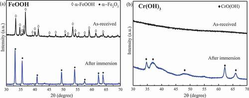
shows the XRD patterns showing phase change in FeOOH and Cr(OH)3 after the autoclave experiments (360 °C for 28 h). The other specimens such as Fe2O3, Cr2O3, ZrO2, and Zr(OH)4 were found to be stable (not shown). The as-received FeOOH was goethite (#81-0464) and totally dehydrated into hematite upon exposure to the autoclave. The as-received Cr2O3 powder was eskolaite (#84-1616) and was stable. The as-received chromium hydroxide powder was amorphous and transformed into CrO(OH) (#89-2696) upon exposure to the autoclave. The as-received ZrO2 was mainly m-ZrO2 (#86-1451) and minor t-ZrO2 (#79-1769). In the autoclaved ZrO2, the intensity of the tetragonal phase relative to that of monoclinic phase became weaker, indicating phase transformation into the monoclinic phase upon autoclaving. The as-received zirconium hydroxide powder was amorphous and transformed into m-ZrO2 (plus minor t-ZrO2).
Figure 1. XRD patterns for (a) FeOOH and (b) Cr(OH)3 before and after autoclave experiments.
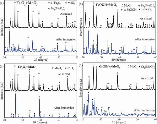
shows the XRD patterns showing phase changes in the compounds under autoclave conditions. It was found that Fe2O3, FeOOH, Cr(OH)3, and Zr(OH)4 reacted with MoO3, producing m-Fe2(MoO4)3, m-Cr2(MoO4)3 (#78-1654), and m-Zr(MoO4)2 (#86-1451), respectively. No obvious reaction products were detected in the other compounds, suggesting that Cr2O3 and ZrO2 would not react with MoO3 in the high-temperature aqueous environment.
Figure 2. XRD patterns for powder mixtures before and after autoclave experiments. (a) Fe2O3 and MoO3; (b) FeOOH and MoO3; (c) Cr2O3 and MoO3; and (d) Cr(OH)3 and MoO3.
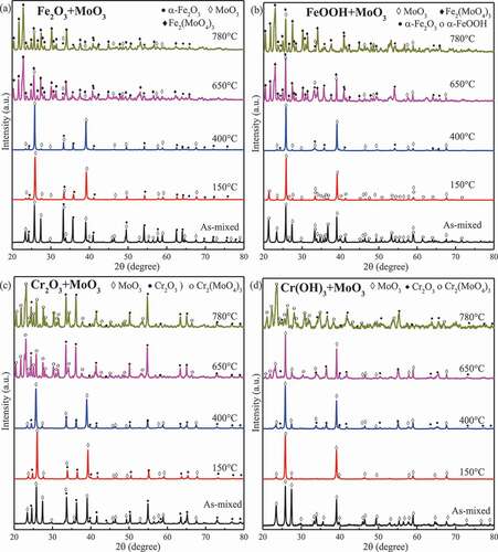
shows the examples of XRD measurement data showing phase changes in FeOOH and Cr(OH)3 upon furnace experiments, namely exposure to air at temperatures ranging from 150 °C to 1000 °C for 24 h. No phase transformations were detected in Fe2O3 and Cr2O3. FeOOH and amorphous Cr(OH)3 transformed into Fe2O3 and α-Cr2O3 (eskolaite) at 400 °C, respectively, and then remained unchanged until 1000 °C. The peaks of t-ZrO2 disappeared above 900 °C. Amorphous Zr(OH)4 was dehydrated and transformed into m- and t-ZrO2 above 650 °C, while the intensity of the peaks of t-ZrO2 became weaker at higher temperature but did not disappear. The XRD data showing phase changes in compounds exposed to air in the furnace experiment are collected in . Fe2O3, Cr2O3, and ZrO2 reacted with MoO3 above 650 °C, producing m-Fe2(MoO4)3, m-Cr2(MoO4)3, and h-Zr(MoO4)2 (#77-1784), respectively. FeOOH, Cr(OH)3, and Zr(OH)4 were firstly dehydrated into the corresponding oxides at 400 °C, 400 °C, and 650 °C, respectively, and then reacted with MoO3 to form the corresponding molybdate compounds at 650 °C.
Figure 3. XRD patterns for (a) FeOOH and (b) Cr(OH)3 exposed to air at different temperatures for 24 h.
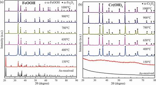
Figure 4. XRD patterns for powder mixtures exposed to air at different temperatures for 24 h. (a) Fe2O3 and MoO3; (b) FeOOH and MoO3; (c) Cr2O3 and MoO3; and (d) Cr(OH)3 and MoO3.
FeOOH, Cr(OH)3, and Zr(OH)4 were unstable and transformed into Fe2O3, Cr2O3, and ZrO2 in the 360 °C aqueous environment while the starting temperatures for dehydration reactions in air were higher than 360 °C. It was reported that high-temperature water can influence reactions through phase behaviors, solute–solvent collisions, diffusion limitations, and cage effects, while may also participate in a reaction as reactants or as catalysts, thereby lowering the activation energy and promoting the chemical reaction [Citation11]. The lower dehydration temperature in the aqueous environment should be ascribed to the influence of the high-temperature water. FeOOH transformed into Fe2O3 at 150–400 °C in the furnace, which agrees with the report [Citation12] that the decomposition of α-FeOOH to α-Fe2O3 occurs at 270–325 °C. For Cr(OH)3 in the aqueous environment, the first dehydration to form CrO(OH) occurs at 55 °C or higher, and grimaldiite (CrO(OH)) is dehydrated to Cr2O3 at about 300–325 °C [Citation13]. Thus, Cr(OH)3 was hydrothermally decomposed into CrO(OH) in the 360 °C aqueous environment. In air, the literature [Citation14] reported that chromium hydroxide firstly loses water to form amorphous CrO(OH) at temperatures ranging from room temperature to 215 °C, followed by complete transformation into Cr2O3 at 409 °C, which agrees with the phenomena that the amorphous form was detected until that Cr(OH)3 transformed into Cr2O3 at 400 °C as shown in ). Picquart et al. [Citation15] reported that the amorphous zirconium hydroxide begins to be gradually dehydrated into tetragonal zirconia at 400 °C, the bulk crystallization occurred at 447 °C, and the mixture of monoclinic and tetragonal phases formed at 600 °C while the monoclinic phase became the dominant form from 900 °C. This report agrees with the observation in this work that the amorphous Zr(OH)4 transformed into ZrO2 and crystalized at 400–600 °C. In addition, the monoclinic phase was dominant from 900 °C according to the increase in the relative intensity of the monoclinic phase.
For ZrO2, three polymorphs can exist at different temperature ranges: monoclinic phase at <1170 °C, tetragonal phase at 1170–2370 °C, and cubic phase above 2370 °C; however, the cubic and tetragonal phases can be partially or fully stabilized at room temperature by several cations such as Y3+, Ca2+, and Mg2+ [Citation16]. It has been reported that m-to-t and t-to-m phase transformations occur at 1127–1207 °C and 977–1052 °C, respectively [Citation17]. But in an aqueous environment, the tetragonal phase could transform into monoclinic phase at 400 °C or even at room temperature due to the changes in the surface energy upon adsorption of water [Citation18]. In this research, it was found that tetragonal phase partially transformed into the monoclinic phase at 360 °C and started to transform at 900 °C in the furnace. Therefore, these results coincide with the literatures [Citation17,Citation18].
In the furnace, solid-state reactions of Fe2O3, Cr2O3, and ZrO2 with MoO3 did not occur at 400 °C but at 650 °C. Therefore, it is reasonable to deduce that the starting temperature for these reactions is 400–650 °C. The starting temperature of Fe2O3–MoO3 reaction reported in the literature is incongruent due to the different starting reactants. Brookes et al. [Citation19] found that the Fe2O3–MoO3 reaction occurred at 500 °C with Fe2O3 and MoO3 as the reactants, while El-Geassy et al. [Citation20] reported that ferric molybdate formed when the compound of ferrous oxalate and ammonium molybdate was heated up to 428 °C. Hence, the solid-state reaction between Fe2O3 and MoO3 could occur at around 500 °C. Cr2(MoO4)3 was synthetized by Oudghiri-Hassani via heating an oxalate precursor in static air at 600 °C [Citation21]. Therefore, this report is consistent with our result that Cr2O3–MoO3 reaction occurred at 400–650 °C. Xie et al. [Citation22] have reported that the ZrO2–MoO3 reaction rate is very slow at 500–600 °C and became faster above 700 °C. The remaining ZrO2 and MoO3 were still detected after 24 h at 650 °C, which should be ascribed to the slow reaction rate below 700 °C. Therefore, it could be concluded according to the literature that the starting temperatures for Fe2O3–MoO3, Cr2O3–MoO3, and ZrO2–MoO3 reactions are 427–500 °C, 600 °C, and 500–600 °C, indicating that activation energy of Fe2O3–MoO3 is lower than that for others.
m-Fe2(MoO4)3, m-Cr2(MoO4)3, and trigonal-Zr(MoO4)2 were detected in the furnace experiments. Many of molybdates are known to be polymorphic [Citation23]. m-Fe2(MoO4)3 reversibly transforms into orthorhombic at 518 °C [Citation24]. Cr2(MoO4)3 exhibits a monoclinic phase as well as a orthorhombic phase, and the transition temperature is 385 °C [Citation25]. Zr(MoO4)2 was reported to undergo a reversible phase transformation at 679 °C from the low-temperature phase (monoclinic structure) to the high-temperature phase (trigonal structure) [Citation26]. Therefore, Fe2(MoO4)3 and Cr2(MoO4)3 are in a monoclinic structure presumably transforming from an orthorhombic structure when cooled down. On the contrary, Zr(MoO4)2 is in a trigonal phase in the air environment. The lower phase transformation rate for Zr(MoO4)2 than that for Fe2(MoO4)3 and Cr2(MoO4)3 may contribute to the existence of trigonal Zr(MoO4)2 at room temperature. Garrido Pedrosa et al. [Citation27] also obtained trigonal Zr(MoO4)2 from the solid-state reaction between ZrO2 and MoO3. Consequently, Fe2(MoO4)3, Cr2(MoO4)3, and Zr(MoO4)2 reversibly transform to the high-temperature forms from low-temperature forms around 500 °C, 400 °C, and 679 °C, respectively.
In light of decomposition, Fe2(MoO4)3, Cr2(MoO4)3, and Zr(MoO4)2 existed below 780 °C, suggesting that they are stable or that the decomposition rate is very low even at 780 °C. Information on the decomposition is limited, and the decomposition temperature of Fe2(MoO4)3 seems inconsistent. Kersen et al. [Citation28] have reported that Fe2(MoO4)3 is highly stable below 850 °C and decomposed completely at 1200 °C. Said [Citation29] found that Fe2(MoO4)3 began to decompose at 800 °C. The accurate decomposition temperature of Cr2(MoO4)3 is unavailable, and it could decompose above 810 °C, accompanied by sublimation of MoO3 [Citation25]. Zr(MoO4)2 decomposes above 800 °C accompanied by the sublimation of MoO3 [Citation30]. Accordingly, under the LWR normal and accident conditions, molybdates that can be formed are Fe2(MoO4)3, Cr2(MoO4)3, and Zr(MoO4)2, all stable below 800 °C.
In the high-temperature aqueous environment, Cr2O3 and ZrO2 did not react with MoO3, but all hydroxides and Fe2O3 reacted with MoO3 and produced monoclinic molybdate compounds. In the high-temperature solution, MoO3 reacts with water according to the following scheme [Citation31]:
Reaction (2) changed the solid–solid reaction to solid–liquid reaction (oxides and hydroxide with H2MoO4), thereby possibly decreasing the activation energy to form the molybdate compounds. Also, the activation energy of Fe2O3–MoO3 is possibly lower than Cr2O3–MoO3 and ZrO2–MoO3 because the starting temperature for the Fe2O3–MoO3 reaction is lower than that for the latter two reactions. Therefore, Fe2O3 reacted with MoO3 in 360 °C water, but others did not. In addition, reactions (2) produced molybdate acid, which prefers to react with hydroxides rather than the oxides. Accordingly, all hydroxides reacted with MoO3 at 360 °C in the aqueous environment, much lower than that in the furnace. It is worth noting that all the resulting molybdate compounds in 360 °C water are in low-temperature forms (monoclinic structure). Up to date, Fe2O3–MoO3, Cr2O3–MoO3, and ZrO2–MoO3 reactions in the aqueous environments have not been reported in the published literature.
3.2. Scheme for a bilayer coating
The results of the preliminary experiments showed that MoO3 reacted with Fe2O3, Cr(OH)3, and Zr(OH)4 under normal condition and can react with Fe2O3, Cr2O3, and ZrO2 in abnormal conditions. Based on the results, a scheme for a bilayer coating with the inner and outer layer could be proposed. As the passive layer, the outer layer is expected to prevent the inner layer and the matrix under normal condition from contacting with the coolant or other oxidative compounds. As the active layer, the inner layer, mainly consisting of MoO3, is expected to react with corrosion products in the coolant, thus healing the coating due to reaction product deposition when a crack occurs.
Under normal condition, the outer layer is not allowed to react with the inner layer (MoO3). Hence, Fe2O3 is not suitable for the outer layer because of the Fe2O3–MoO3 reaction in the aqueous environment. In the air environment, physical stability of the candidate materials is required to avoid the volume change which is the factor leading to the separation of the coating under LOCA condition. From this point of view, Cr2O3 and m-ZrO2 are suitable as the candidate materials for the outer layer since they are physically stable up to 1000 °C. As found in the experiments, Cr2O3 and ZrO2 reacted with MoO3 to produce the corresponding molybdate compounds in the air environment above 650 °C. Accordingly, Cr2O3–MoO3 and ZrO2–MoO3 reactions at high temperature may strengthen the adhesion of the coating in LOCA condition, and the two reactions could be considered as a non-autonomic process because the temperature change is the trigger for the reactions. These molybdate compounds, formed above 650 °C, will start to decompose when the temperature is higher than 800 °C. The decomposition of molybdate compounds and the sublimation of MoO3 are endothermic processes, which would help to slow down the temperature increase under LOCA condition. Therefore, the inner layer of the coating could be made from the compound of MoO3, Cr2O3, and ZrO2.
Considering that the inner layer is made of MoO3, Cr2O3, and ZrO2, the fabrication temperature should be lower than 500 °C to avoid the Cr2O3–MoO3 and ZrO2–MoO3 reactions. A MoO3–Cr2O3 film with a thickness of 300 nm was obtained by atmospheric pressure chemical vapor deposition in oxygen under ambient conditions [Citation32]. In the fabrication process, the precursors were Mo(CO)6 and Cr(CO)6, and the temperatures of the deposition substrate, sublimator, and annealing were 200 °C, 70 °C, and 300–500 °C, respectively. The resulting coating was reasonably smooth, and no Cr2(MoO4)3 was detected in the coating. Plasma spraying was successful for the fabrication of MoO3–Cr2O3 compound coating, and no combination reactions were found [Citation33]. The sol–gel method is also an accessible method for low-temperature fabrication. (NH4)6Mo7O24·H2O, MoO2(OH)(OOH), and Mo(OC3H7)5 can form the MoO3 coating after heating to 160 °C, 275 °C, and 110 °C, respectively [Citation34,Citation35]. The mixture of CrCl3·6H2O and nitric acid [Citation36] or the mixture of Cr(NO3)3·6H2O and (NH2)2·H2O [Citation37] was used as the precursor of Cr2O3 below 500 °C. It is worth noting that Cr(OH)3 would form firstly and be dehydrated to Cr2O3 at 400 °C as discussed above. Zirconium propoxide and zirconium oxychloride were used as the precursor of ZrO2 [Citation38]. Similarly, Zr(OH)4 would be obtained before ZrO2. However, as described above, Zr(OH)4 would be dehydrated to form t- and m-ZrO2 at 400–600 °C. Pure monoclinic phase could not be obtained until 900 °C. Therefore, two phases coexist if the precursor of ZrO2 is heat treated below 500 °C to avoid the ZrO2–MoO3 reactions. It has been described in the previous part that t-ZrO2 could transform into m-ZrO2 in an aqueous environment. Thus, the coexistence of t- and m-ZrO2 in the coating would deteriorate the stability of the coating. Consequently, it is a problem to add ZrO2 into the inner layer of the coating. As a summary, pure Cr2O3 and Cr2O3–MoO3 compounds are feasible as the outer and inner layers of the coating, respectively. The corrosion products of the fuel cladding, Zr(OH)4 and ZrO2, could react with MoO3 in aqueous and air conditions at certain temperatures and could contribute to the self-healing, possibly resulting in adhesion of the coating.
3.3. Feasibility of Fe2O3–MoO3 reaction as a self-healing reaction
As described in the previous part, Fe2O3 is the main component of the corrosion products and reacted with MoO3 under normal condition. Therefore, the Fe2O3–MoO3 reaction was chosen as the candidate self-healing process, and further investigation was required. The XRD patterns for Fe2O3–MoO3 compound powder immersed at 100 °C, 200 °C, 300 °C, and 360 °C for 3 h and at 360 °C for 0.5, 3, 6, 9, and 12 h are shown in . As shown in ), the peaks ascribed to Fe2(MoO4)3 were detected on the Fe2O3–MoO3 powders after immersion at 300 °C, so the critical starting temperature of the Fe2O3–MoO3 reaction is between 200 °C and 300 °C. The relative peak intensity of MoO3 became weaker when the immersion temperature was increased to 360 °C, suggesting that the rate of Fe2O3–MoO3 reactions increased with increasing temperature.
Figure 5. XRD patterns for Fe2O3–MoO3 composite powder immersed at (a) different temperatures for 3 h and (b) at 360 °C for different immersion time.
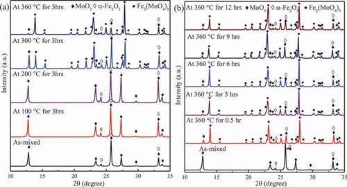
) shows the XRD patterns for the compound of Fe2O3 and MoO3 derived by autoclave experiments (360 °C in pure water). Fe2(MoO4)3 was produced in the 0.5 h test, and the relative intensity of the spectra for Fe2(MoO4)3 almost did not change when the immersion time was lengthened.
The defined RIR values derived from the XRD patterns (not shown here) of the Fe2O3–αAl2O3 powder and MoO3–αAl2O3 powder were 4.88 and 1.9 for MoO3 and Fe2O3, respectively. The RIR value for Fe2(MoO4)3 in ICDD #83-1701 is 1.21. Using these values, the molar ratio of Fe2(MoO4)3/Fe2O3 as a function of immersion temperature and time was estimated and is shown in . The ratio of Fe2(MoO4)3/Fe2O3 started increasing above 200 °C and approached unity at 360 °C. To derive the reaction rate of the Fe2O3–MoO3 reaction, a model was employed to translate the reaction into a rate equation. For solid-state reactions, models have been proposed based on certain assumptions: (1) nucleation models, which consider the formation and growth of nuclei as the rate-limiting step; (2) geometrical contraction models, which consider the progress of the product layer from the surface to the inner crystal as the rate-limiting step; (3) diffusion models, where diffusion of reactant or product is considered to be rate limiting; and (4) reaction-order models, which consider the reaction as a homogeneous kinetic process [Citation39]. In this research, prior to pouring into the autoclave, Fe2O3 powders were thoroughly stirred with MoO3 powders in water. Additionally, the molar ratio of Fe2(MoO4)3/Fe2O3 in Fe2O3–MoO3 powders approached unity. First-order function based on the reaction-order model and Avrami–Erofeyev functions based on the nucleation models show a similar tendency [Citation39]:
Figure 6. The molar ratio of Fe2(MoO4)3/Fe2O3 as a function of the immersion (a) temperature and (b) time.

where C is the concentration fraction, k is the rate constant, and t is the time; n = 1 in first-order function, while n = 2, 3, 4 for Avrami–Erofeyev functions. Thus, the rate of them can be written as a unified form:
where R is the rate of the reaction. Hence, the reaction rates of Avrami–Erofeyev functions increase at first and then decrease, while the rate of first-order function decreases with the reaction progress.
As shown in ), the molar ratio of Fe2(MoO4)3/Fe2O3 increased quickly in the first 2 h and approached completion after 6 h, indicating that the reaction rate was fast initially but decreased subsequently. The curve in ) might follow the first-order function. The fitting equation is
The rate constant was (2.3 ± 0.5) h–1, and the coefficient of determination (R2) was 0.96. However, the fitting curve deviates from the experimental data above 0.5 h and approached to unity much earlier than the experimental result. The reaction process was possibly hindered by the formation of products surrounding the reactants, and so the reaction rate decreased subsequently.
Accordingly, the n in EquationEquation (4)(4)
(4) should be modified and is lower than 1 for Fe2O3–MoO3 reaction and could be derived by refitting the experimental data with EquationEquation (3)
(3)
(3) , thereby deducing EquationEquation (6)
(6)
(6) as following:
As shown in ), the fitting curve of EquationEquation (6)(6)
(6) matches well with the experimental data, and R2 is 0.98. The rate constant is (3.0 ± 1.5) h–1, and m = (0.4 ± 0.1), and the rate of the Fe2O3–MoO3 reaction could be deduced by replacing k and n in EquationEquation (4)
(4)
(4) with the fitted results. The value of R that corresponds to the slope of the curve in ) approaches infinity when t is close to zero, but R drops close to zero in 2 h, indicating that the reaction rate is so fast that the products, which hinder the reaction process, could be formed in a short time.
The temperature of the bulk coolant ranges from 278 °C to 287 °C and from 275 °C to 315 °C in the boiling water reactor (BWR) and the pressurized water reactor (PWR), respectively. The surface temperature of the fuel cladding is about 360 °C. Since the Fe2O3–MoO3 reaction in water takes place above 200 °C, and the reactions exhibited a fast rate at 360 °C, the reaction has the potential ability to produce the molybdate compounds in a short time. As previously described, Fe2O3 (a corrosion product in the coolant) is expected to diffuse into the cracks on the coating and react with MoO3 (inner layer) to produce the insoluble Fe2(MoO4)3. This insoluble compound deposits and repairs the cracks under normal condition, and this healing reaction is an autonomic process because the crack itself is the instigation for the healing reaction. In LOCA condition, the Fe2(MoO4)3 would not decompose until 850 °C. The decomposition reactions produce Fe2O3, which could still fill the cracks and one more product, MoO3, takes heat away by sublimation, helping to cool down the fuel to a certain extent.
With regard to the source of Fe2O3, Fe2O3 is the main corrosion product in the coolant, and it was reported that the crud in LWRs can grow to 10–100 μm thick [Citation40]. Therefore, the corrosion products in the coolant would supply Fe2O3 for the Fe2O3–MoO3 reaction. In addition, external injection of minor Fe2O3 to the coolant is also an alternative method to increase the concentration of Fe2O3 in the coolant. Consequently, this reaction is possible for use as the self-healing process.
4. Summary
In this study, a novel scheme for a self-healing coating was proposed, and the candidate materials for the coating and the potential self-healing reaction were assessed by means of autoclave and furnace experiments. The pure Cr2O3 layer and the compound of Cr2O3 and MoO3 could be used as the outer layer and inner layer, respectively, due to their compatibility under normal condition and fabricability. Fe2O3–MoO3 reactions exhibited a potential ability to self-heal the cracks because of a high reaction rate under normal condition. The self-healing mechanism involves Fe2O3 (a corrosion product in the coolant) diffusion into a crack on the coating and subsequent reaction with MoO3 (inner layer) produces insoluble Fe2(MoO4)3 which deposits and repairs the cracks under normal condition. Further work will involve determining the chemical concentration and the thickness of the coating.
Acknowledgments
This study is supported by the project of ‘The development of self-healing intelligence on nuclear fuel cladding’ carried out under the Center of World Intelligence Project for Nuclear S&T and Human Resource Development by the Ministry of Education, Culture, Sports, Science and Technology of Japan.
Disclosure statement
No potential conflict of interest was reported by the authors.
References
- Northwood DO. The development and applications of zirconium alloys. Mater Des. 1985;6(2):58–70.
- Duan Z, Yang H, Satoh Y, et al. Current status of materials development of nuclear fuel cladding tubes for light water reactors. Nucl Eng Des. 2017;316:131–150.
- Yamamoto Y, Pint B, Terrani K, et al. Development and property evaluation of nuclear grade wrought FeCrAl fuel cladding for light water reactors. J Nucl Mater. 2015;467:703–716.
- Hallstadius L, Johnson S, Lahoda E. Cladding for high performance fuel. Prog Nucl Energy. 2012;57:71–76.
- Park JH, Kim HG, Park J, et al. High temperature steam-oxidation behavior of arc ion plated Cr coatings for accident tolerant fuel claddings. Surf Coat Technol. 2015;280:256–259.
- Maier BR, Garcia-Diaz BL, Hauch B, et al. Cold spray deposition of Ti2AlC coatings for improved nuclear fuel cladding. J Nucl Mater. 2015;466:712–717.
- Duan Z, Yang H, Kano S, et al. Oxidation and electrochemical behaviors of Al2O3 and ZrO2 coatings on Zircaloy-2 cladding by thermal spraying. Surf Coat Technol. 2018;334:319–327.
- Hazelton RF Characteristics of fuel CRUD and its impact on storage, handling, and shipment of spent fuel. Richland (WA): Pacific Northwest Lab. (USA); 1987. (Report no. PNL-6273).
- Daub K, Van Nieuwenhove R, Nordin H. Investigation of the impact of coatings on corrosion and hydrogen uptake of Zircaloy-4. J Nucl Mater. 2015;467:260–270.
- Kim HG, Kim LH, Jung YI, et al. Adhesion property and high-temperature oxidation behavior of Cr-coated Zircaloy-4 cladding tube prepared by 3D laser coating. J Nucl Mater. 2015;465:531–539.
- Akiya N, Savage PE. Roles of water for chemical reactions in high-temperature water. Chem Rev. 2002;102(8):2725–2750.
- Rumyantsev RN, Il’yin AA, Pimenova KR, et al. Conditions of formation of iron molybdate(III) by ceramic and mechanochemical syntheses. Russ J Gen Chem. 2017;87(9):2224–2228.
- Ziemniak S, Jones M, Combs K. Solubility and phase behavior of Cr (III) oxides in alkaline media at elevated temperatures. J Solution Chem. 1998;27(1):33–66.
- Gomes AS, Yaghini N, Martinelli A, et al. A micro-Raman spectroscopic study of Cr(OH)3 and Cr2O3 nanoparticles obtained by the hydrothermal method. J Raman Spectrosc. 2017;48(10):1256–1263.
- Picquart M, López T, Gómez R, et al. Dehydration and crystallization process in sol–gel zirconia. J Therm Anal Calorim. 2004;76(3):755–761.
- Gauna M, Conconi M, Gomez S, et al. Monoclinic-tetragonal zirconia quantification of commercial nanopowder mixtures by XRD and DTA. Ceram Silik. 2015;59(4):318–325.
- Rendtorff N, Garrido L, Aglietti E. Thermal behavior of mullite–zirconia–zircon composites. Influence of zirconia phase transformation. J Therm Anal Calorim. 2011;104(2):569–576.
- Oskarsson M, Ahlberg E, Pettersson K. Phase transformation of stabilised zirconia in water and 1.0 M LiOH. J Nucl Mater. 2001;295(1):126–130.
- Brookes C, Wells P, Cibin G, et al. Molybdenum oxide on Fe2O3 core-shell catalysts: probing the nature of the structural motifs responsible for methanol oxidation catalysis. ACS Catal. 2013;4(1):243–250.
- El-Geassy AA, Seetheraman S. Synthesis and characterization of nano-structured molybdenum-iron intermetallics by gas-solid reaction technique. IOP Conf Ser: Mater Sci Eng. 2016;119(1):1–10.
- Oudghiri Hassani H. Synthesis, characterization and application of chromium molybdate for oxidation of methylene blue dye. J Mater Environ Sci. 2018;9(3):1051–1057.
- Xie S, Chen K, Bell AT, et al. Structural characterization of molybdenum oxide supported on zirconia. J Phys Chem B. 2000;104(43):10059–10068.
- Sleight A, Brixner L. A new ferroelastic transition in some A2(MO4)3 molybdates and tungstates. J Solid State Chem. 1973;7(2):172–174.
- Rapposch M, Anderson J, Kostiner E. Crystal structure of ferric molybdate, Fe2(MoO4)3. Inorg Chem. 1980;19(11):3531–3539.
- Walczak J, Kurzawa M, Filipek E. Studies on chromium(III) molybdate and equilibria in the CrVO4-Cr2(MoO4)3 system. Thermochim Acta. 1989;150(1):133–140.
- Auray M, Quarton M, Tarte P. Crystal data for two molybdates MIV(MoO4)2 with MIV = Zr, Hf. Powder Diffr. 1987;2(1):36–38.
- Garrido Pedrosa AM, Melo DMA, Souza MJB, et al. Synthesis, structure, and morphology of bifunctional catalysts based on zirconia modified by molybdenum oxide. Inorg Mater. 2008;44(3):285–290.
- Kersen U, Keiski R, editors. Phase evolution, microstructure, and gas-sensing properties of the Fe2(MoO4)3 system. Chemical sensors VI: chemical and biological sensors and analytical methods. Honolulu (HI): The Electrochemical Society, Inc; 2004. cited Oct 3–8.
- Said -A-A-A. Role of the structure and electronic properties of Fe2O3-MoO3 catalyst on the dehydration of isopropyl alcohol. Bull Chem Soc Jpn. 1992;65(12):3450–3454.
- Miura E, Shimada T, Ogushi S, et al. Effect of molybdenum oxide(VI) on the synthesis of zircon. Nippon Kagaku Kaishi. 1973;1973(10):1879–1885. in Japanese.
- Dadze TP, Kashirtseva GA, Novikov MP, et al. Solubility of MoO3 in NaClO4 solutions at 573 K. J Chem Eng Data. 2017;62(11):3848–3853.
- Ivanova T, Gesheva K, Hamelmann F. Morphological and structural study of CVD MoO3-Cr2O3 films. ECS Trans. 2009;25(8):221–228.
- Lyo IW, Ahn HS, Lim DS. Microstructure and tribological properties of plasma-sprayed chromium oxide–molybdenum oxide composite coatings. Surf Coat Technol. 2003;163:413–421.
- Liu J, Wu X, Chen S, et al. Low-temperature MoO3 film from a facile synthetic route for an efficient anode interfacial layer in organic optoelectronic devices. J Mater Chem C. 2014;2(1):158–163.
- Dong W, Dunn B. Sol-gel synthesis and characterization of molybdenum oxide gels. J Non-Cryst Solids. 1998;225:135–140.
- Jung YS, Kim KH, Jang TY, et al. Enhancement of photocatalytic properties of Cr2O3-TiO2 mixed oxides prepared by sol–gel method. Curr Appl Phys. 2011;11(3):358–361.
- Balouria V, Singh A, Debnath A, et al., editors. Synthesis and characterization of sol–gel derived Cr2O3 nanoparticles. Proceedings of the 56th DAE solid state physics symposium; [cited 2011 Dec 19–23] Kattankulathur, India: AIP; 2014.
- Tyagi B, Sidhpuria K, Shaik B, et al. Synthesis of nanocrystalline zirconia using sol–gel and precipitation techniques. Ind Eng Chem Res. 2006;45(25):8643–8650.
- Khawam A, Flanagan DR. Solid-state kinetic models: basics and mathematical fundamentals. J Phys Chem B. 2006;110(35):17315–17328.
- Coyle CP Synthesis of CRUD and its effects on pool and subcooled flow boiling [master’s thesis]. Boston (MA): Massachusetts Institute of Technology; 2016.