
 ?Mathematical formulae have been encoded as MathML and are displayed in this HTML version using MathJax in order to improve their display. Uncheck the box to turn MathJax off. This feature requires Javascript. Click on a formula to zoom.
ABSTRACT
Compact time-of-flight (TOF) measurement systems are desirable for easy installation in various facilities. To achieve such compact systems, one of the key considerations is the design of the neutron moderator. Therefore, systematic studies on moderators considering both neutron energy resolution and neutron intensity are important. In this paper, to design an epithermal neutron moderator at ambient temperature for short-distance TOF measurements, the neutron intensity and energy resolution of epithermal neutrons have been studied using the Monte Carlo simulation code PHITS with JENDL-4.0 for various types of moderators. The neutronic characteristics of a moderator comprising several components were evaluated. The relationships between the moderator dimensions and both the energy resolution and intensity of the epithermal neutrons were determined. From the obtained results, the appropriate high-resolution moderator designs for the short-distance TOF measurements were proposed.
1. Introduction
Epithermal neutrons have been applied for measuring the neutron data in the resolved resonance region [Citation1,Citation2], neutron resonance analysis of nuclear materials (NMs) as a non-destructive analysis (NDA) technique [Citation3], and pulsed epithermal neutron imaging [Citation4–6]. For applications that require the use of pulsed neutron sources together with a neutron time-of-flight (TOF) technique [Citation1,Citation3], measurements are typically carried out at TOF facilities. Most of these facilities are relatively large-scale as required for high-resolution neutron TOF measurements [Citation7]. As a result, their non-academic use has been limited by the considerable costs involved. Recently; however, with the scientific and technological developments, compact pulsed neutron sources have been developed [Citation8–11], and the cost of using neutrons has also been decreasing.
One of the applications of the compact neutron sources is neutron resonance transmission analysis (NRTA) [Citation3]. NRTA is a useful method for NDA of NMs for improving the efficiency of probate operations to ensure the peaceful use of NMs. It is an effective technique for measuring highly radioactive NMs because the interrogated NMs and the detector are placed at a distance from each other, and it does not require any special sample preparation [Citation12]. However, since the installation of large-scale TOF measurement systems in many facilities requiring tight control of NMs is practically challenging, the TOF systems need to be compact to use NRTA. For this reason, numerous studies on compact NRTA systems have been conducted in recent years [Citation10–17]. Paradela et al. (2016) [Citation12] studied the requirements for a NRTA system. Paradela group suggested that the neutron energy resolution (∆En/En) of about 0.008 in TOF measurements was sufficient to analyze complex transmission data of NMs, such as debris of melted fuel. From the viewpoint of nuclear nonproliferation, Tsuchiya et al. (2018) [Citation13] studied the concept of a compact NRTA system using a deuterium-tritium (DT) source to identify special NMs, such as Pu isotopes, 235U, etc., in nuclear fuels. In this study, the neutron energy resolution (∆En/En) at 6.67 eV resonance of 238U was calculated about 0.14 for a flight distance 5 m with a pulse width 10 μs. Thus, it is important to achieve the desired energy resolution appropriately according to research purposes.
As a part of our project investigating a compact NRTA system, we have also started studying a short-distance TOF measurement system using a laser-driven neutron source (LDNS) [Citation18–21]. Shortening the neutron flight distance for TOF measurements is important because it reduces the space requirements and shielding costs, while increasing the utilization efficiency of neutrons from the source in the 4 pi direction. On the other hand, when the neutron flight distance becomes shorter, the neutron energy resolution deteriorates. To achieve a high energy resolution even with a short flight distance, the neutron source must have a short pulse width. As a new type of a neutron source, the LDNS provides remarkably short neutron pulses due to the extremely short pulse width of the laser (<ps) and the short generation time width of the accelerated ions [Citation22,Citation23].
However, no matter how short the pulse width of the neutron source is, it is significantly broadened when the fast neutrons emitted from the source are slowed down in the moderator. Therefore, to achieve a high energy resolution even for a short flight distance, it is important to properly design the neutron moderator. For this reason, numerous studies for designing neutron moderators have been conducted in the past [Citation6,Citation24–32]. In addition, various systematic studies, such as the relationships between the neutron intensity and time distribution of the moderated neutrons [Citation33,Citation34] and reflector’s effects for various moderator assemblies [Citation35], have been also carried out by many research groups.
The aim of the present study is to design an epithermal neutron moderator at ambient temperature for NRTA to achieve a high neutron intensity with a good energy resolution at short flight distances not exceeding 5 m. For this purpose, the energy spectra and time distributions of neutrons emitted from hydrogen-based moderators were calculated using the Monte Carlo simulation code PHITS [Citation36] and the evaluated nuclear data library JENDL-4.0 [Citation37] for several designs with varying moderator dimensions and materials. By analyzing the simulation results, we have formulated a guideline on how to choose the moderator dimensions and materials. In addition, the results of the present study will be useful for designing neutron sources or moderators for a wide range of applications using thermal neutrons as well as epithermal neutrons because slowing down process (1/E spectrum) is strongly correlated with thermalized process (Maxwellian spectrum) in a hydrogenous moderator at ambient temperature [Citation38].
2. Materials and methods
2.1 Moderator conceptual design
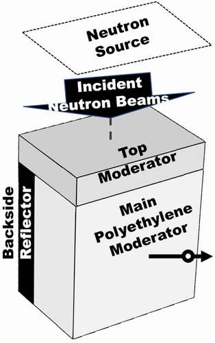
shows a conceptual design of a neutron moderator to slow down effectively fast neutrons (~MeV) generated from a pulsed neutron source to the epithermal neutron energy region. The neutron moderator was configured so that the direction of the incident neutron and neutron detector were at 90 degrees to each other, which intended to prevent directly detecting the strong gamma-flashes generated by the beam–target interaction at a neutron detection system. The moderator consisted of the following three parts: main moderator, top moderator, and reflector.
Figure 1. Conceptual design of neutron moderator.
The purpose of the main moderator was to slow down the fast neutrons (~MeV) to the epithermal energy region (<100 eV). Polyethylene (PE) that contains hydrogen has been typically used as a moderator for slowing down fast neutrons efficiently [Citation8,Citation15,Citation32] because the high moderating efficiency of hydrogen and high hydrogen density of PE are advantageous to make a compact size neutron moderator. Furthermore, PE exists in solidstate and exhibits excellent machinability. For these reasons, in the present study, high-density PE (0.96 g/cm3) was selected as the main moderator material. To investigate how the neutron intensity and energy resolution depend on the moderator dimensions, various areas and thicknesses of the PE moderator were tried.
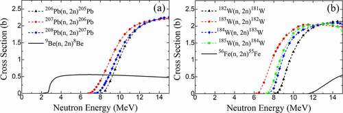
Hydrogen, a common material used in moderators, has a low moderation effect in the high neutron energy region (>MeV), because its neutron cross sections are rapidly reduced in the MeV energy range, as shown in . For this reason, a top moderator was added to slow down the fast neutrons (~MeV) to the keV–MeV energy region more efficiently and to increase the neutron population. The materials selected for the top moderator had large (n, xn) reaction cross sections in the MeV range, which was expected to increase the neutron population by the (n, xn) reactions. The concept of the top moderator system coupled with the main moderator is similar to the premoderator concept studied by Kiyanagi et al. (1994) [Citation29]. The system to use the (n, xn) reactions for increasing the neutron intensity [Citation30] was already applied as the Be reflector system [Citation31] in Japan Spallation Neutron Source (JSNS) of J-PARC/MLF [Citation39,Citation40]. In the present study, lead (Pb), beryllium (Be), and tungsten (W) were adopted, and also iron (Fe) as a reference. shows the (n, xn) reaction cross sections of Pb, Be, W, and Fe, and we can identify thresholds for the (n, xn) reaction cross sections of each top-moderator material from . To estimate the change of the epithermal neutron intensity by the top moderator, various thicknesses of each top-moderator material were evaluated. For comparison, PE was also tried as a material of the top moderator.
Figure 2. Neutron total cross section of hydrogen.
Figure 3. (n, xn) reaction cross sections for 9Be, 206Pb, 207Pb, 208Pb, 182W, 183W, 184W, and 56Fe.
Because the moderated neutrons were emitted from the moderator in the 4 pi direction, a suitable reflector system was crucial to improve the neutron intensity in the desired direction. The widely used neutron reflector materials, carbon (C), Pb, Be, and W, were also considered as the candidates in this study. To estimate the neutronic characteristics of the reflector system, the backside reflectors adopted varying thicknesses of each candidate material. For comparison, PE was again employed, too.
2.2 Calculations
The geometry adopted for the simulations using the PHITS with the JENDL-4.0 is shown in . In the simulations, the JENDL-4.0 thermal scattering law of PE was used for more accurate calculations. As an incident neutron energy, 1, 2.45, and 14 MeV mono-energetic incident neutrons were used considering fission sources or (γ, n) sources (average energy around <2 MeV), DT sources (average energy 2.45 MeV), deuterium-tritium sources (average energy 14 MeV), and also 10 MeV as a reference. An incident neutron source was placed above the moderator, and the beam spot size was set equal to the upper surface area of the moderator, as shown in . From the incident neutron source, the 1, 2.45, 10, or 14 MeV mono-energetic neutron beams were irradiated parallel to the upper surface of the moderator. To obtain the energy spectrum of neutrons escaping from the moderator, an idealized detector-1 (10 cm in diameter) with a 100% detection efficiency was placed 0.5 m away from the side surface of the moderator, as shown in , and the neutrons passing through it were counted. In this paper, the detector-1 position (0.5 m) was determined with consideration of the simulation efficiency, such as computation time, although installing the detector-1 at 5.0 m away from the moderator was more ideal. The obtained energy spectra were integrated between 1 and 100 eV to evaluate the intensity of the epithermal neutrons.
Figure 4. Moderator geometry for design simulations.
To evaluate the time distribution of the moderated neutrons, another idealized detector (detector-2) with a 100% detection efficiency was placed at the side surface of the moderator, as shown in , for recording the time and energy of neutrons escaping from the moderator. The neutron energy of the TOF measurement is expressed as the following equation:
where En and mn are the neutron energy and mass, respectively. L is the distance between the surface of the moderator and the front face of the detector, T is the neutron flight time. From EquationEquation (1)(1)
(1) , the energy resolution (∆En/En) of the TOF measurement can be calculated from the following equation
where ∆L and ∆T are the uncertainties in the distance and time, respectively. Because distance L can be determined by metric measurements with a small uncertainty ∆L (a few mm), the energy resolution (∆En/En) depends practically only on the time resolution (∆T/T) [Citation41]:
The neutron TOF uncertainty, ∆T, mainly depends on two factors. One is the pulse width of the neutrons decelerating in the moderator, and the other is the pulse width of an ion beam [Citation41,Citation42]. In the present study, we only focused on the time distribution of the moderated neutrons in the moderators and defined ΔT as the full width at half maximum (FWHM) of the time distribution.
3. Results
3.1 Main moderator designs and their characteristics
(a) shows examples of the relationship between the time and intensity for each energy of the moderated neutrons, where the peaks were normalized to match with 1.0. In this simulation, the incident neutron energy E0 was 1 MeV, and the moderator consisted of only the PE main moderator (5 × 10 × 10 cm3). The time and energy of neutrons escaping from the moderator were recorded by the detector-2, and the FWHMs of time distributions (1, 10, and 100 eV) were used as ∆T. The neutron flight time T at En = 1, 10, and 100 eV for L = 5 m was calculated by Equationequation (1)(1)
(1) . (b) shows the energy resolutions at L = 5 m adopting these times and uncertainties. As shown in (b), the energy resolutions were found to be almost constant in the epithermal neutron energy range (1–100 eV). These neutronic characteristics for the energy resolution were consistent with previous studies [Citation3,Citation41,Citation42]. In this paper, the energy resolution at En = 10 eV for L = 5 m was used as representative for comparisons and discussions.
Figure 5. (a) Simulated time distributions of neutron intensity originating from deceleration process in moderator. (b) Energy resolutions of moderator for L = 5 m. Moderator made only of PE (5 × 10 × 10 cm3).
A comparison of the epithermal neutron intensities and energy resolutions with changing the area A × A cm2 and thickness B of the PE main moderator without any other parts for E0 = 1 and 2.45 MeV is shown in . In the simulations, when changing the area, the PE thickness B was assumed as either 2 or 5 cm, and when changing the thickness, a constant area of 10 × 10 cm2 was adopted. The moderated neutron fluences of the 2 × 10 × 10 cm3 and 5 × 10 × 10 cm3 moderators are listed in .
Figure 6. Comparison of relative intensities (black) of neutron fluences (1–100 eV) as functions of PE area (a and b) and PE thickness (c). Intensity calculated as neutron fluence multiplied by moderator upper surface area and compared to intensity when using A × A = 10 × 10 cm2 and B = 2 cm. Comparison of energy resolutions (red) at En = 10 eV with L = 5 m for moderators with varying PE area (a and b) and varying PE thickness (c).
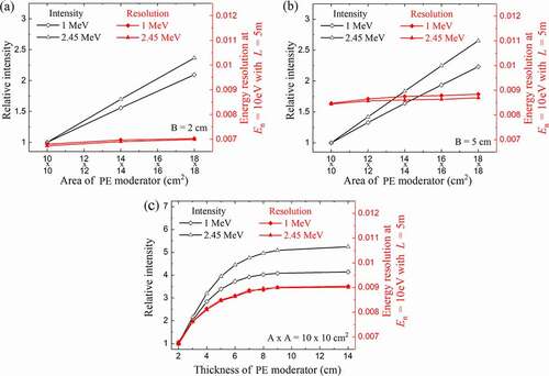
Table 1. Simulated moderator neutron fluences (/cm2/eV/neutron source) 0.5 m away from the moderator surface.
As shown in (a), (b), and (c), the observed changes in neutron intensity and energy resolution demonstrated different trends with changing area and thickness. For the neutron intensity, when the moderator area increased, the neutron intensity also increased proportionally to the moderator area. This was because the neutrons emitted from the moderator were increased gradually with increasing the emission surface of the moderator, and the number of incident neutrons were increased gradually with increasing the incident neutron source size. On the other hand, when the moderator thickness increased, the neutron intensity was maximized with increasing the PE thickness. This was because the moderation length for the epithermal neutrons in polyethylene is of about 1 cm, thus, the thermalized and captured neutrons in the moderator increased with the increase in the PE moderator thickness. Obtained neutronic characteristics for the neutron intensity were consistent with previous systematic study of Kopecky et al. (2016) [Citation16]. Furthermore, our results showed a very similar tendency to the experimental study of Kiyanagi et al. (1982) [Citation26] for the thermal-neutron emission intensity as a function of the moderator area/thickness. This was due to the strong correlation between 1/E and Maxwellian spectra. For the energy resolution, when the thickness of the moderator increased from 2 to 8 cm, the energy resolution largely changed, whereas with the increasing PE thickness above 8 cm, it hardly changed. This was because the energy resolution strongly depended on the moderator dimension. In (a) and (c), where the thickness is below 3 cm, the high energy resolutions (below 0.008) were obtained, which was due to small moderator dimensions. Obtained neutronic characteristics for the energy resolution (time distribution) showed a similar tendency to the experimental results of Kiyanagi (1985) [Citation27] for the FWHM of the time distribution at 29.4 meV neutrons as a function of the moderator thickness.
Note that the neutron source targets were fixed in previous studies [Citation16,Citation26,Citation27], and in the present study, the incident neutron source size was changed in proportion to the upper size of the moderator.
3.2 Top moderator designs and their characteristics
In the simulations described in this section, the moderator consisted of the main moderator and a top moderator, and a constant size of the former (5 × 10 × 10 cm3) was adopted. The relationships between the neutron intensity and top moderator thickness, C = 0–4 cm for E0 = 1, 2.45, 10, and 14 MeV, are shown in , while selected neutron fluences are listed in .
Figure 7. Comparison of relative intensities of neutron fluences (1–100 eV) as function of top moderator thickness. Intensity compared to that without top moderator.
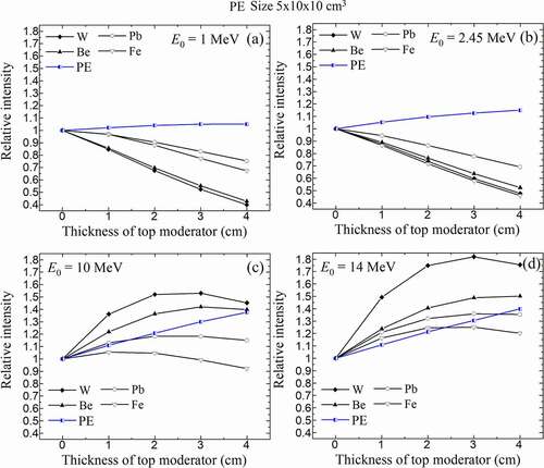
For E0 = 1 and 2.45 MeV, as shown in (a) and (b), the neutron intensity achieved using PE in the top moderator was better than for all the other materials. For E0 = 10 and 14 MeV, the results shown in (c) and (d) indicated that combining the main moderator with a top moderator made of either Be or W increased the intensity of the epithermal neutrons significantly. This was mainly due to the combination of atomic densities and cross sections of (n, xn) reactions for each top moderator material. Be and W had high atomic densities and (n, xn) reaction cross sections and showed good performances as the top moderator at E0 = 10 and 14 MeV.
We also investigated the neutron intensity gains for each 2-cm thick top moderator at each incident neutron energy. shows the comparison of the neutron intensity gains, where the intensity gain was calculated as the ratio of the intensity with the top moderator to that without top moderator at each incident energy. The results showed that using either Be or W as a material for the top moderator was effective for E0 larger than 6.5 MeV or 8.5 MeV, respectively. This was mainly because the (n, xn) threshold reactions of Be and W, as shown in . As a result, the neutron intensity gains of Be and W increased rapidly at above about E0 = 2.5 and 7.5 MeV. On the other hand, the gain of PE increased gradually with the incident neutron energy. This was because the moderation length in the moderator increased with the incident neutron energy, and then the increase (gain) of the moderation efficiency was larger gradually with the incident neutron energy.
Figure 8. Comparison of neutron intensity gains (black and blue) of each top moderator for each incident neutron energy. Intensity gain calculated as ratio of intensity with top moderator to that without top moderator at each incident energy. Comparison of energy resolutions (red) at En = 10 eV with L = 5 m for main moderator combined with a W top moderator (C = 0 and 2 cm).
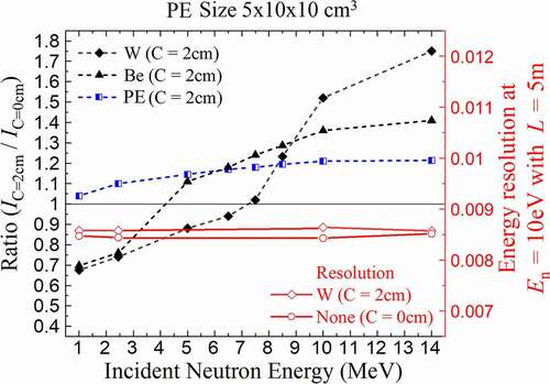
The neutron energy resolutions using a W top moderator with a 2-cm thickness and without a top moderator are also plotted in . The change in the energy resolution caused by adopting the top moderator was small. The energy resolution was hardly correlated with the incident neutron energy, and this result was consistent with a previous systematic study of Kopecky et al. (2016) [Citation16].
In this paper, W of thickness C = 2 cm was selected as the top moderator for E0 = 10 and 14 MeV, while no top moderator was adopted for E0 = 1 and 2.45 MeV. These two designs were adopted for the analyses shown in Sections 3.3 and 3.4.
3.3 Reflector designs and their characteristics
As described in Section 3.1, when the moderator was thickened to a certain degree, the neutron intensity does not increase because the thermalized and absorbed neutrons in the moderator were increased. Therefore, to enhance the utilization efficiency of the moderated neutrons to the detector direction, the backside reflector was added to the moderator. As reflector materials, materials having small capture cross sections as well as large neutron scattering cross sections in the keV–MeV range were considered. In the simulations discussed in this section, the size of the PE main moderator was assumed to be either 2 × 10 × 10 cm3 or 5 × 10 × 10 cm3. The relationships between both neutron intensity and energy resolution and the backside reflector thickness D = 0–4 cm for E0 = 1, 2.45, 10, and 14 MeV are shown in .
Figure 9. Comparison of relative intensity of neutron fluences (1–100 eV) as function of backside reflector thickness. Intensity calculated as neutron fluence multiplied by moderator upper surface area and compared to that without backside reflector.
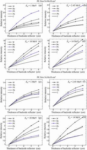
Figure 10. Comparison of energy resolutions at En = 10 eV with L = 5 m for moderator combined with Be, W, and PE backside reflectors (D = 0–4 cm).
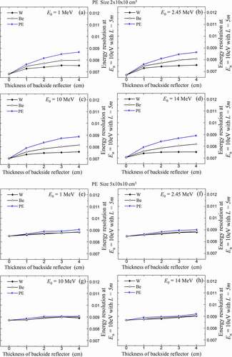
As can be concluded from (e)–(h), when the moderator thickness was 5 cm, both W and Be effectively increased the neutron intensity, especially at high energies. This was mainly because W and Be reflectors had high atomic densities and large scattering cross sections as well as it had (n, xn) reactions. However, as can be seen from (a)–(d), when the moderator thickness was only 2 cm, both Be and W had poorer performances than PE for E0 = 1 and 2.45 MeV because PE had a good performance for the intensity in the PE thickness of 2 to 6 cm as shown in (c). Nevertheless, from the viewpoint of the energy resolution, the Be and W backside reflectors with a thickness of 2 cm delivered significant improvements to the energy resolution, as shown in (a)–(d). The neutrons of about keV–MeV were scattered by the reflector and slowed down in the moderator and then emitted to the detector direction. Because the slowing down process of the neutrons was mainly due to the PE main moderator, the thin PE moderator with the reflector system had been advantageous for the time distribution.
3.4 Figure of merit of moderator
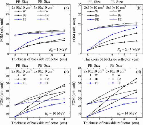
When there are no specific restrictions on the neutron flight distance to achieve the desired energy resolution, it is useful to evaluate the figure of merit (FOM) of the moderator. In the present study, we also investigated the FOMs by using EquationEquation (4)(4)
(4) [Citation27,Citation33].
where I is the neutron intensity emitted from the moderator. shows the FOMs of the moderator assemblies as a function of the moderator and reflector thickness, where the neutron intensity I was compared to that of the 2-thick moderator at each incident energy. For E0 = 1 and 2.45 MeV, as shown in (a) and (b), the 5-cm-thick PE moderator assemblies showed better FOMs than the 2-cm-thick PE moderator assemblies. In this study, the moderator assembly with the highest FOM was the 5-cm-thick PE main moderator with the thick W reflector. Moreover, the 6-cm-thick PE main moderator with the thick W reflector is expected to have the best FOM. The present results showed a similar tendency to the experimental results of Kiyanagi (1985) [Citation27] for the FOM as a function of the moderator thickness. If the neutron flight distance can be adjusted to achieve the desired energy resolution, these designs can be the optimized moderator designs for NRTA. For E0 = 10 and 14 MeV, the moderator assemblies consisting of the W top moderator, thin PE main moderator, and thick W or Be reflector showed high FOMs. This design is useful for a compact NRTA system because it can maintain a high energy resolution at the short neutron flight distance.
Figure 11. Comparison of FOM of moderator as function of moderator and reflector thickness. FOM calculated as intensity/∆T2. Intensity compared to that of 2-cm thick moderator (2 × 10 × 10 cm3) at each incident energy.
4. Conclusions and discussions
The neutron emission spectra and time distributions of the neutrons emitted from several moderators of various designs were predicted via Monte Carlo simulations. Using the simulation results, we calculated and compared the epithermal neutron intensities and energy resolutions for all considered moderator designs. For the PE main moderator, we confirmed that increasing the area of PE with slim dimensions was effective for increasing the neutron intensity while maintaining a good energy resolution. For the top moderator, it was found that Be and W were useful materials for increasing the neutron intensity for E0 larger than 6.5 and 8.5 MeV, respectively. For the backside reflector, Be and W could be effective materials for achieving both good neutron intensity and energy resolution. Furthermore, we also discussed the best designs of the moderator assemblies based on the FOM of the moderator. However, a sufficient long neutron flight distance is required to apply these designs.
The results of the present study provide insights on how to achieve a higher neutron intensity while maintaining a high energy resolution in short-distance TOF measurements by optimizing the moderator design. For example, a hollow cylinder moderator will be placed around the target source as shown in . In , the direction of the incident ion (laser) beam and neutron detector were at 90 degrees. Paradela et al. [Citation12] argued that the total energy resolution (∆En/En) of the measurements considering the detector, data acquisition system, moderator, ion beam pulse width, etc. should be better than 0.008 to analyze confidently complex NMs by NRTA. In order to achieve this resolution with a neutron flight distance of less 5 m, the thickness of the PE moderator cannot be more than about 3 cm. However, by increasing the area of the main moderator with slim dimensions and using a backside reflector and a top moderator depending on the incident neutron energy, the designers of neutron sources (target-moderator-reflector systems) would be able to properly perform designs of moderator assemblies maintaining high energy resolutions even for short-distance TOF measurement systems.
Figure 12. Conceptual design example for neutron source.
In the LDNS, the generation efficiency of the fast neutrons increases with the laser energy, and the energy of the fast neutrons emitted from the LDNS also increases with the laser energy [Citation43–45]. With the development of ultra-intense lasers [Citation46], it is expected that the LDNS will have a very high neutron energy spectrum [Citation19]. The top moderator and reflector system could be effective for high energy neutron sources, such as these LDNSs or DT sources [Citation17].
Finally, because this paper focused on the neutronic characteristics of the moderators at ambient temperature, backgrounds, such as the 2.2 MeV gamma-rays emitted by the hydrogen neutron capture reaction in the moderator, have not been studied. However, in the TOF measurements with a short flight distance, because the gamma background events increase exponentially with decreasing flight distance, it is important to evaluate the moderated neutron beams including the backgrounds. For this reason, we will investigate the time-dependent backgrounds of moderated neutron beams and estimate the ratios of the gamma-ray to neutron emission intensity depending on the moderator geometries and neutron flight distances in future research.
Acknowledgments
This research was implemented under the subsidy for “promotion of strengthening nuclear security and the like” of the MEXT (the Ministry of Education, Culture, Sports, Science, and Technology of the Japanese government). Then, this research was conducted using the supercomputer HPE SGI8600 in the Japan Atomic Energy Agency.
Disclosure statement
No potential conflict of interest was reported by the author(s).
References
- Schillebeeckx P, Becker B, Danon Y, et al. Determination of resonance parameters and their covariances from neutron induced reaction cross section data. Nucl Data Sheets. 2012;113(12):3054–3100.
- Lee J, Nishiyama J, Hori J, et al. Neutron total cross section measurements of polyethylene using time-of-flight method at KURNS-LINAC. J Nucl Sci Technol. 2020;1(1):1–8.
- Schillebeeckx P, Becker B, Harada H, et al. Neutron resonance spectroscopy for the characterization of materials and objects. J Instrum. 2012;7(3):C03009.
- Kiyanagi Y. Neutron Imaging at Compact Accelerator-Driven Neutron Sources in Japan. J Imaging. 2018;4(4):55.
- Kamiyama T, Sato H, Miyamoto N, et al. Energy sliced neutron tomography using neutron resonance absorption spectrometer. Nucl Instr Meth Phys Res A. 2009;600(1):107–110.
- Takahashi Y, Kiyanagi Y, Watanabe K, et al. Development of a neutron source for imaging at the electron linac facility in Kyoto University research reactor institute. Phys B Condens Matter. 2018;551:488–491.
- Mondelaers W, Schillebeeckx P. GELINA, a neutron time-of-flight facility for high-resolution neutron data measurements. Notiziario. 2006;11:19–25.
- Anderson IS, Andreani C, Carpenter JM, et al. Research opportunities with compact accelerator-driven neutron sources. Phys Reports. 2016;654:1–58.
- Kobayashi T, Ikeda S, Otake Y, et al. Completion of a new accelerator-driven compact neutron source prototype RANS-II for on-site use. Nucl Instr Meth Phys Res A. 2021;994:165091.
- Sato H, Kamiyama T, Kiyanagi Y. Pulsed neutron imaging using resonance transmission spectroscopy. Nucl Instr Meth Phys Res A. 2009;605(1–2):36–39.
- Ito D, Takahashi Y, Sano T, et al. Identification and quantification of nuclear nuclides using a pulsed neutron imaging technique. JPS Conf Proc. 2019;24:011018.
- Paradela C, Alaerts G, Heyse J, et al. Neutron Resonance Analysis System Requirements. Publications Office of the European Union; 2016. (Report no. EUR 28239 EN).
- Tsuchiya H, Kitatani F, Maeda M, et al. Development of neutron resonance transmission analysis as a non-destructive assay technique for nuclear nonproliferation. Plasma Fusion Res. 2018;13:2406004.
- Kusumawati Y, Ozawa I, Mitsuya Y, et al. X-band electron LINAC-based compact neutron source for nuclear debris on-site screening using short-distance neutron resonance transmission analysis. E-J Adv Maint. 2019;11:46–64.
- Engel EM, Klein EA, Danagoulian A. Feasibility study of a compact neutron resonance transmission analysis instrument. AIP Adva. 2020;10:1015051.
- Kopecky S, Heyse J, Paradela C, et al. Study of a compact NRA system. publications office of the European union; 2016. (Report no. EUR 28245 EN).
- Klein EA, Naqvi F, Bickus JE, et al. Neutron-resonance transmission analysis with a compact deuterium-tritium neutron generator. Phys Rev Applied. 2021;15(5):054026.
- Bang W, Dyer G, Quevedo HJ, et al. Optimization of the neutron yield in fusion plasmas produced by Coulomb explosions of deuterium clusters irradiated by a petawatt laser. Phys Rev E. 2013;87(2):023106.
- Petrov GM, Higginson DP, Davis J, et al. Generation of high-energy (>15 MeV) neutrons using short pulse high intensity lasers. Phys Plasmas. 2012;19(9):093106.
- Mirfayzi SR, Alejo A, Ahmed H, et al. Experimental demonstration of a compact epithermal neutron source based on a high power laser. Appl Phys Lett. 2017;111(4):04410.
- Mirfayzi SR, Yogo A, Lan Z, et al. Proof-of-principle experiment for laser-driven cold neutron source. Sci Rep. 2020;10(1):20157.
- Macchi A, Borghesi M, Passoni M. Ion acceleration by superintense laser-plasma interaction. Rev Mod Phys. 2013;85(2):751–793.
- Tanaka H, Kurosawa S, Yamaji A, et al. Evaluation of neutron pulse width in laser-driven neutron source using organic scintillator; Proc. 2019 IEEE NSS/MIC, 2019 Oct 26 - Nov 2; Manchester, UK; 2020.
- Day DH, Sinclair RN. Neutron moderator assemblies for pulsed thermal neutron time-of-flight experiments. Nucl Instr Meth. 1969;72(3):237–253.
- Mildner DFR, Boland BC, Sinclair RN, et al. A cooled polyethylene moderator on a pulsed neutron source. Nucl Instr Meth. 1978;152(2–3):437–446.
- Kiyanagi Y, Iwasa H. Pulsed Neutron intensity from rectangular shaped light water moderator with fast-neutron reflector. J Nucl Sci Technol. 1982;19(5):352–358.
- Kiyanagi Y. Neutronics of polyethylene thermal moderator of wing and slab geometries on pulsed neutron source. J Nucl Sci Technol. 1985;22(11):934–938.
- Robinson RA, Carpenter JM. On the use of switch functions in describing pulsed neutron moderators. Nucl Instr Meth Phys Res A. 1991;307(2–3):359–365.
- Kiyanagi Y, Watanabe N, Iwasa H. Premoderator studies for a coupled liquid-hydrogen moderator in pulsed spallation neutron sources. Nucl Instr Meth Phys Res A. 1994;343(2–3):558–562.
- Sordo F, Fernandez-Alonso F, Terron S, et al. Baseline design of a low energy neutron source at ESS-Bilbao. Phys Procedia. 2014;60:125–137.
- Maekawa F, Harada M, Oikawa K, et al. First neutron production utilizing J-PARC pulsed spallation neutron source JSNS and neutronic performance demonstrated. Nucl Instr Meth Phys Res A. 2010;620(2–3):159–165.
- Iked Y, Taketani A, Takamura M, et al. Prospect for application of compact accelerator-based neutron source to neutron engineering diffraction. Nucl Instr Meth Phys Res A. 2016;833:61–67.
- Michaudon A. The production of moderated neutron beams from pulsed accelerators. Reactor Sic Technol. 1963;17:165–186.
- Kai T, Teshigawara M, Watanabe N, et al. Optimization of coupled hydrogen moderator for a short pulse spallation source. J Nucl Sci Technol. 2002;39(2):120–128.
- Kiyanagi Y. Effects of reflector on intensity of thermal neutrons emitted from moderator for pulsed neutron source. J Nucl Sci Technol. 1987;24(6):490–497.
- Sato T, Iwamoto Y, Hashimoto S, et al. Features of particle and heavy ion transport code system (PHITS) version 3.02. J Nucl Sci Technol. 2018;55(6):684–690.
- Shibata K, Iwamoto O, Nakagawa T, et al. JENDL4.0: a new library for nuclear science and engineering. J Nucl Sci Technol. 2011;48(1):1–30.
- Beckurts KH, Wirtz K. Neutron Physics. Berlin: Springer; 1964.
- Iked Y. Current status of 1 MW pulse spallation neutron source (JSNS) of J-PARC. J Nucl Mater. 2005;343(1–3):7–13.
- Iked Y. J-PARC status update. Nucl Instr Meth Phys Res A. 2009;600(1):1–4.
- Kino K, Furusaka M, Hiraga F, et al. Energy resolution of pulsed neutron beam provided by the ANNRI beamline at the J-PARC/MLF. Nucl Instr Meth Phys Res A. 2014;736:66–74.
- Sano T, Hori J, Takahashi Y, et al. Analysis of energy resolution in the KURRI-LINAC pulsed neutron facility. Plompen A, Hambsch FJ, Schellebeecks P, et al. editors. Proc. ND 2016. 2016 Sep 11-16 Bruges Belgium Les Ulis Cedex:EDP sciences. 2017 Vol. 146. 03031.
- Fuchs J, Antici P, d’Humières E, et al. Laser-driven proton scaling laws and new paths towards energy increase. Nature Phys. 2006;2(1):48–54.
- Anderson IS, Andreani C, Carpenter JM, et al. Research opportunities with compact accelerator-driven neutron sources. Phys Rep. 2016;654:1–58.
- Takagi Y, Iwata N, Humieres E, et al. Multivariate scaling of maximum proton energy in intense laser driven ion acceleration. Phys Review Res. 2021;3(4):043140.
- Morrison JT, Feister S, Frische KD, et al. MeV proton acceleration at kHz repetition rate from ultra-intense laser liquid interaction. New J Phys. 2018;20(2):022001.