Abstract
This paper describes the procedure of changing from 2D to 3D treatment planning guidelines for post-mastectomy radiotherapy in Denmark. The aim of introducing 3D planning for post-mastectomy radiotherapy was to optimize the target coverage and minimize the dose to the normal tissues. Initially, it was investigated whether it was possible to find a treatment technique alternative to the one recommended by the Danish Breast Cancer Cooperative Group (DBCG). A dosimetric comparison of a combined photon/electron 3-field technique (3F) and a partial wide tangent technique (PWT) was carried out on individual planning CT-scans from seven patients selected to represent a wide range of sizes and shapes of chest walls. The heart dose was lower for PWT than for 3F, however, for both techniques the dose was within the accepted constraints. The lung dose was higher but acceptable for six of the seven patients with PWT. The dose to the internal mammary nodes (IMN) was not satisfactory for five of the seven patients for 3F, whereas only two of the seven patients had a minimum dose lower than 95% of the prescribed dose with PWT. Finally, the dose to the contralateral breast was increased when using PWT compared to 3F. It was concluded that PWT was an appropriate choice of technique for future radiation treatment of post-mastectomy patients. A working group was formed and guidelines for 3D planning were developed during a series of workshops where radiation oncologists and physicists from all radiotherapy centres participated. This work also included a definition of the tissue structures needed to be outlined on the planning CT-scan. The work was initiated in 2003 and the guidelines were approved by the DBCG Radiotherapy Committee in 2006. The first of January 2007 the 3D guidelines had been fully implemented in five of the seven radiotherapy centres.
The first national guidelines for adjuvant radiotherapy of breast cancer in Denmark were made by the Danish Breast Cancer Cooperative Group (DBCG) in 1977. Since then, the majority of patients referred to post-mastectomy radiotherapy in Denmark have been treated with a combined photon/electron 3-field technique (3F) Citation[1], Citation[2]. Patients treated with this technique after mastectomy have an improved survival compared to non-irradiated patients Citation[3], Citation[4] and no excess cardiac morbidity has been observed for the irradiated patients Citation[5]. However, 3F is best suited for planning on a simulator. In recent years, there has been a general change in treatment planning from 2D planning on a simulator to 3D planning based on a CT scan and it has been shown that virtual simulation of breast cancer patients may be more time effective Citation[6]. The technological development of accelerators with multi-leaf collimators has also offered some new possibilities for more time effective treatment techniques compared to techniques with field matching between photon and electron fields Citation[7]. In a study using 3D treatment planning to compare seven common techniques for post-mastectomy radiotherapy, Pierce et al. Citation[8] concluded that none of the techniques were uniformly superior for each of the end points: target coverage and potential lung and cardiac toxicity. However, the analysis showed that the partial wide tangent technique (PWT) was the most appropriate compromise. Based on this, the DBCG Radiotherapy Committee in 2003 decided to initiate a revision of the guidelines for post-mastectomy radiotherapy to include CT-based treatment planning. A working group was formed and the guidelines were developed during a series of workshops up to the final approval in 2006 (). This paper describes the process in changing from a clinically well established 2D based technique to a 3D based treatment technique.
Table I. Timeline for the development of DBCG CT-based radiotherapy guidelines.
Methods
A detailed dosimetric comparison of 3F Citation[2] and PWT Citation[8] was performed on CT scans from seven patients. Six of the patients were selected from a large group of post-lumpectomy patients previously studied Citation[9] to obtain patients with a very wide range of sizes and shapes of the chest wall. The group consisted of three patients with left-sided and three patients with right-sided cancer. For this study; their body outline was corrected to exclude the breast virtually when introduced into the dose planning system. The seventh patient was a post-mastectomy patient with right-sided cancer. All seven patients had been immobilised in an individually formed VacFix cushion (PAR Scientific, Denmark) with both arms above their head. They were CT-scanned in treatment position with a slice distance of 1 cm.
Delineation of regional lymph nodes (LN) was performed according to the guidelines of Dijkema et al. Citation[10]. One radiation oncologist carried out the delineation of the internal mammary LN's (IMN) in the first four intercostal (IC) spaces on all patients. The axilla level I-III LN, the heart and the contralateral breast were also contoured by this radiation oncologist. Lung contours were defined by automatic density tracking by a radiographer. Dose planning was carried out by the same physicist for all seven patients. Helax TMS version 6.1B (Nucletron, The Netherlands) with the pencil beam algorithm was used for the dose planning. The prescription dose and fractionation was 48 Gy in 24 fractions, 5 fractions/week. The dose constraints for the treated volumes were minimum 90% and maximum 110% of the prescribed dose. The two techniques planned for each patient were:
3F (a): The periclavicular-axillary region and the lateral part of the chest wall were planned with an anterior 6 MV photon field angled 12° from vertical to the contralateral side. Shielding blocks were applied for the humeral head, the larynx/trachea and the chest wall. The dose for the field was normalized to a point positioned in the prescription depth according to the 2D guidelines. If the maximum dose for the anterior 6 MV photon field exceeded 110% in the dose plan, the field was supplemented with an anterior 18 MV photon field with the same beam parameters and blocks as the 6 MV field to obtain a sufficient target dose in the deepest part of the target. A bolus of 5 mm was placed over the scar in the photon field. The IMN and chest wall were planned with two electron fields angled at 0°. The width of the IMN field was 6 cm at the cranial border right below the sterno-clavicular junction and 5 cm right above the fifth rib, which defined the caudal border of the field. The energies of the electron fields were determined by the depth from the skin to the pleura. The depth of the minimum of the prescribed dose for the IMN field was determined as the depth to the pleura plus 5 mm to include the IMN, whereas the depth of the chest wall field was determined as the depth to the pleura minus 10 mm to exclude the ribs. The thickness of the chest wall was eventually adjusted with a bolus to obtain a match between the depth and the 85% isodose curve. Apart from the standard 3F plan, a modified 3F plan (3F CT) was also created. This plan was identical to 3F except that the border between the two abutting electron fields was defined to include the complete IMN target as delineated on the CT-scan in the IMN field.
PWT (b): The chest wall including the IMN was planned with medial and lateral 6 MV tangential fields. The dose was normalized to a point at the central axis of the fields. If the tangential fields included a part of the heart, it was shielded from the tangential photon fields by the MLC and a medial anterior electron field was added (not shown in b). A divergence free cranial match line was planned for the match between the tangential fields and the periclavicular-axillary photon field which was angled 12° from vertical to the contralateral side. MLC shielding was created for the humeral head and the larynx/trachea. The dose for this field was normalized in the same way as the photon field of the 3F technique. In some patients (the same patients as for 3F) the 6 MV periclavicular-axillary photon field was mixed with an anterior 18 MV field to avoid underdosing in the deepest part of the target.
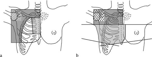
Figure 1. The two treatment techniques with the field borders shown in black. a. 3F: The dark grey area shows the photon field, the light grey area the IMN electron field and the white area the chest wall electron field. b. PWT: The dark grey area shows the periclavicular-axillary photon field whereas the light grey area shows the tangential photon fields.
Dose volume histograms (DVHs) were calculated for the heart, ipsilateral lung, IMN and the contralateral breast and the comparison of the two techniques was based on the DVHs. For the ipsilateral lung, the percentage of the volume that received more than 20 Gy (V20) and the mean lung dose (Dmean) were chosen for comparison. The dose constraints used for the lung were V20 < 35% and Dmean <18 Gy Citation[11], Citation[12] For the heart, the percentages of the volume receiving more than 20 Gy and 40 Gy (V20 and V40, respectively) were used. The dose constraints for the heart were V20 < 10% and V40 < 5%. These limits were derived from Gagliardi et al. Citation[13] when accepting a risk of late cardiac mortality of 1.5%. The dose to the contralateral breast was evaluated on basis of the mean and the maximum dose whereas the minimum and mean doses were chosen as parameters for the IMN.
For the axillary LN the depths of level II and III were measured and compared to the depths used for standard dose calculation after a simulation. According to the simulation based DBCG guidelines the depth for dose calculation for patients with less than 6 positive LN is 4 cm whereas the ½AP distance at the humeral head is used for patients with more than 6 positive LN. Finally, the field borders in the periclavicular-axillary region as defined in the simulation based guidelines were compared with the axillary lymph node levels to obtain a translation from 2D to 3D which is in accordance with earlier clinical practice.
A number of workshops were arranged to obtain a nationwide agreement about how the future post-mastectomy radiation therapy should be carried out. The participants in these workshops were physicists and radiation oncologists from each radiotherapy centre. Prior to each workshop the participants performed target delineation and dose planning on the same case patient (patient no. 1).
Results
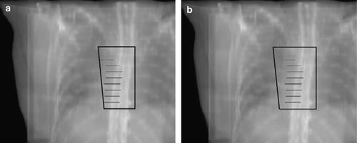
shows an example of the DVHs for the IMN, heart, ipsilateral lung and contralateral breast for one of the right-sided cancer patients while presents an example of the standard IMN field and the corresponding CT based field.
Figure 2. Dose volume histograms for patient no. 1. a. Internal mammary nodes, b. Ipsilateral lung, c. Heart, d. Contralateral breast (note scale on x-axis). Dashed line: Partial wide tangent technique, dotted line: The DBCG combined photon/electron 3-field technique, solid line: A plan identical to the combined photon/electron 3-field technique except that the border between the two abutting electron fields is defined to include the IMN in the medial field.
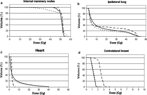
Figure 3. The IMN electron field. a. The standard field size defined on basis of the DBCG guidelines. b. The field defined from the information about the localisation of the IMN from the CT-scanning with a lateral margin of 10 mm.
The minimum and mean doses to IMN for PWT and 3F () demonstrate that the standard 2D field size for the IMN field of the 3F technique did not adequately cover the delineated IMN volume in six of the seven patients. The mean dose was lower for 3F CT compared to PWT. However, a higher mean dose to the IMN is expected for a technique with tangential photon fields including lung when a pencil beam algorithm is used for dose calculation. Two of the patients with a left-sided lesion (no. 4 and 6) had some of the heart included in the standard wide tangent photon fields and the PWT plan for these patients also included a medial electron field. The low mean IMN dose for PWT for patient no. 6 was due to the fact that the distance from the skin to the IMN target was about 5 cm in a part of the medial electron field due to a large body mass index of the patient.
Table II. The internal mammary node minimum and mean dose in percent of the prescribed dose for the partial wide tangent technique (PWT) and the DBCG combined photon/electron 3-field technique (3F). Also included is data for a dose plan 3F CT.
shows the Dmean and V20 values for the ipsilateral lung. The lung V20 values were in the range 28.2–43.6% and Dmean in the range 14.4–21.3 Gy for PWT whereas the ranges for 3F and 3F CT were V20: 15.4–24.8%, Dmean: 9.2–12.6 Gy and V20: 17.1–26.3%, Dmean: 10.1–14.7 Gy, respectively. The lung dose parameters for 3F CT were higher than those for 3F with standard IMN field size. This is due to the fact that a larger area of the lung is irradiated with the high electron energy in most of the patients when the IMN field is defined on basis of the IMN structure delineated on the CT-scan. V20 and Dmean were higher for PTW than for 3F but within the limits of the DBCG guidelines for all patients except one. This patient had a chest wall shape which resulted in inclusion of a considerable part of the lung in the tangential fields.
Table III. The percentage of the ipsilateral lung volume that receives more than 20 Gy (V20) and the mean lung dose (Dmean) for the partial wide tangent technique (PWT) and the DBCG combined photon/electron 3-field technique (3F). Also included is data for a dose plan 3F CT.
The V20 and V40 values for the heart are shown in . For all the patients the lowest heart dose was obtained with PWT except for patient no. 5 where the V20 value was almost identical for the two techniques whereas the V40 value was slightly higher for PWT. The heart doses for both techniques were within the limits (V20 < 10% and V40 < 5%).
Table IV. The percentage of the heart volume that receives more than 20 Gy and 40 Gy (V20 and V40, respectively) for the partial wide tangent technique (PWT) and the DBCG combined photon/electron 3-field technique (3F). Also included are data for a dose plan 3F CT.
The mean dose to the contralateral breast is presented in . PWT resulted in an increase of the mean dose to the contralateral breast from a median value of 1.6% for 3F to 4.7% for PWT. The contralateral breast dose was largest for PWT but the increase in the absolute median dose to the contralateral breast for a prescribed dose of 48 Gy was from 0.8 Gy for 3F to 2.3 Gy for PWT.
Table V. The mean dose to the contralateral breast in percent of the prescribed dose.
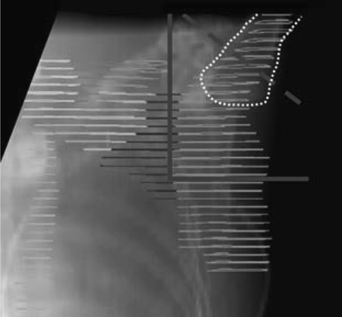
The depths from the ventral skin surface to the dorsal limit of axilla level II and III measured on the CT scans are shown in . The mean depth of level II and III for the seven patients was 6.0 and 4.6 cm, respectively. The figure also includes the depths measured according to the depth of dose calculation given in the 2D guidelines. The depth of the axillary level III LN exceeded 4 cm for all patients except one whereas both level II and III LN were shallower than the ½AP at the humeral head. The latter depth was therefore more than sufficient to obtain the prescribed dose to the LN in the field. A comparison of the simulation based field borders and the extension of level 2 and 3 is presented schematically in . This shows that the field border of the 2D guidelines corresponded to the junction between level II and I.
Figure 4. Depths in the axilla. The bars show the range of the depth of level II (solid lines) and level III (dotted lines). The open circle represents the ½AP at humeral head whereas the solid circle shows the depth 4 cm.
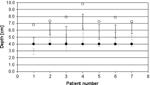
Figure 5. The lateral field borders according to the 2D guidelines are shown with solid (>10 LN removed and <6 LN positive) and dashed (<10 LN removed or >6 LN positive) grey lines. The humeral head is shown with a dotted white line.
Discussion
The seven patients in this study were carefully selected from a larger group of patients in order to exemplify patients with a wide range of different chest wall sizes and shapes. Therefore the results obtained in this comparison of the two techniques can be considered to be representative for patients with a wide variation in anatomy.
It was found that the heart V20 and V40 values were smaller for PWT than for 3F. In the work of Pierce et al. Citation[8] PWT included a medial electron field and shielding of the heart if some of the heart was included in the standard tangential photon fields. For two of the left-sided patients in this study such an electron field was applied. However, if standard wide tangent photon fields were planned for these patients, the IMN minimum and mean dose increased to 94.6% and 102.4% (pt. no. 4) and 94.5% and 103.3% (pt. no. 6). For this plan, the heart values increased to V20 = 8.4%, V40 = 4.6% (pt. no. 4) and V20 = 7.3% and V40 = 4.6% (pt. no. 6) but did not exceed the dose constraints of 10% and 5%, respectively. The V40 limit of 5% is in agreement with the probability of complication for a 6% of heart volume irradiated to a dose of 40 Gy given by Gagliardi et al. Citation[14], whereas no excess risk of cardiac mortality was found for a 12% heart volume irradiated to a dose of 20 Gy. Krueger et al. Citation[15] studied the dose to various cardiac structures for five different postmastectomy radiotherapy techniques including PWT and one called the reverse hockey stick (RHS) which is similar but not exactly identical to 3F. They found that cardiac substructures receive the least radiation exposure with PWT. The doses for the RHS technique were comparable to PWT for most substructures except for the left anterior descending artery where the dose for the RHS technique was higher. It has been shown Citation[16] that further dose sparing to cardiac structures may be obtained by using breathing adapted radiotherapy for tangential irradiation after lumpectomy. Identical dose sparing can be obtained for mastectomy patients (personal communication, A.N. Pedersen). Also the lung dose can be decreased by using such techniques Citation[16], Citation[17]. The PWT plan for one of the patients had a mean lung dose of more than 18 Gy and a V20 > 35%. A physical mean dose of 18 Gy corresponds to a risk of radiation induced pneumonitis of 5% Citation[11], whereas moderate pulmonary complications were found among 11% of the breast patients treated with loco-regional radiotherapy with a V20≈35% Citation[18]. Thus, the problem of higher lung doses for some patients with PWT may be reduced by using respiratory gating during treatment. This is a feasible solution, as it has been shown Citation[19] that gating can be used without an increase in the slot time for treatment.
It was found that the 2D standard IMN field did not include the total IMN volume delineated on the CT scans in six of the seven patients. The localisation of the IMN varies considerably Citation[20]. According to a study of the internal mammary chain by scintigraphy in 320 female breast cancer patients Citation[21], a fixed field size of 5 cm across the midline, which is similar to the standard DBCG field size, appeared to be optimal (i.e. not too small and not more than 10 mm too large) in 39% of all cases. Sarnak et al. Citation[22] compared the accuracy of IMN localisation using lymphoscintigraphy and CT and they found that the methods have accuracies of 5 mm and 7 mm, respectively, which are acceptable for radiotherapy.
For several years it has been discussed whether the IMN should be included in the radiation field for postoperative radiotherapy of the breast/chest wall Citation[23] especially for left breast lesions due to the increased heart toxicity associated with IMN irradiation. There is considerable international variation in the attitudes regarding treatment of the IMN Citation[24]. Since 2003, the DBCG guidelines have recommended irradiation of the IMN's for right-sided patients only, thus avoiding the problem of a higher lung dose with PTW when including the IMN in the chest wall fields. When a right-sided patient is treated according to the DBCG guidelines the IMNs in IC1-4 are included in the locoregional lymph node target. It has been found Citation[25] that the metastatic internal mammary lymph nodes are predominantly located in IC1-3. Therefore it may be discussed if it is necessary to include IC4 in the target. If the IMN target is limited to IC1-3, the lung dose may decrease, thereby reducing the risk of radiation induced complications of this organ. Blom-Goldman et al. Citation[26] have shown that a reduction of the V20-value resulted in a lower incidence of clinically significant symptomatic pneumonitis.
Another goal of this work was to transform the 2D based field definition and dose calculation method of the periclavicular-axillary region to 3D without the introduction of several structures to be delineated. Goodman et al. Citation[27] have performed a study where they found that the mean depth and range of depths for the supraclavicular LN were comparable to the mean depth and range for the level III LN. Thus, if a sufficient dose to level III is obtained the dose to the supraclavicular LN will also be sufficient. This study showed that Level II is positioned on average 1.4 cm deeper in the patients than level III, and a sufficient dose to level II implies that the dose to the supraclavicular LN will be sufficient. In the 2D guidelines, the field border was placed close to the junction between level I and II and the inclusion of the entire level II would only be a minor change of the field (). Based on this, it was decided to use the lateral border of level II delineation as lateral field border of the periclavicular-axillary field. The dosimetric requirement for this field is that level II is covered by at least the 90% isodose line. Level II is quite easy to identify on a CT scan because the nodes are defined as lying beneath the pectoralis minor muscle. By requiring only level II to be delineated prior to dose planning the workload will be reduced.
There are different opinions on whether an additional posterior field is necessary as a supplement to the anterior periclavicular-axillary field Citation[27], Citation[28] and there are several possible treatment techniques Citation[29]. Apart from using a supplementary posterior field it is also possible to mix the 6 MV field with an anterior field with the high energy of the accelerator as the depth of both axillary and supraclavicular LN depends on the size of the patient Citation[28]. However, for both methods it is important to note that if only level II is delineated, the dose in the field must be checked by eye to secure a sufficient dose for more superficially placed lymph nodes.
Conclusions
The PWT technique is an appropriate choice of technique for future radiation treatment of post-mastectomy patients. A central part in the development and implementation of the guidelines for 3D radiotherapy planning of post-mastectomy patients has been workshops where radiation oncologists and physicists from all radiotherapy centres participated and discussed the various topics to be handled when changing from 2D to 3D planning. It was beneficial for the process that the same case patient was used repeatedly in the workshops.
By January 2007, the 3D guidelines have been implemented in five of the seven radiotherapy centres. One centre has implemented the 3D technique for a selected group of post-mastectomy patients whereas the last centre is still using the simulation based technique. The time horizon for a fully implementation of the guidelines in these two centres is expected to be less than one year.
References
- Overgaard M, Christensen JJ, Johansen H, Nybo-Rasmussen A, Brincher H, van der Kooy P, et al. Postmastectomy irradiation in high-risk breast cancer patients. Present status of the Danish Breast Cancer Cooperatice Group trials. Acta Oncol 1988; 27: 707–14
- Nielsen HM, Overgaard J, Grau C, Christensen JJ, Overgaard M. Audit of the radiotherapy in the DBCG 82 b&c trials – A validation study of the 1538 patients randomised to postmastectomy radiotherapy. Radiother Oncol 2005; 76: 285–92
- Overgaard M, Hansen PS, Overgaard J, Rose C, Andersson M, Bach F, et al. Postoperative radiotherapy in high-risk premenopausal women with breast cancer who recieve adjuvant chemotherapy. N Engl J Med 1997; 337: 949–55
- Overgaard M, Jensen M-B, Overgaard J, Hansen PS, Rose C, Andersson M, et al. Postoperative radiotherapy in high-risk postmenopausal breast-cancer patients given adjuvant tamoxifen: Danish Breast Cancer Cooperative Group DBCG 82c randomised trial. Lancet 1999; 353: 1641–8
- Højris I, Overgaard M, Christensen JJ, Overgaard J. Morbidity and mortality of ischaemic heart disease in high-risk breast-cancer patients after adjuvant postmastectomy systemic treatment with or without radiotherapy: Analysis of DBCG 82b and 82c randomised trials. Radiotherapy Committee of the Danish Breast Cancer Cooperative Group. Lancet 1999; 354: 1425–30
- Buchali A, Geismar D, Hinkelbein M, Schlenger L, Zinner K, Budach V. Virtual simulation in patients with breast cancer. Radiother Oncol 2001; 59: 267–72
- Sonnik D, Selvaraj RN, Faul C, Gerszten K, Heron DE, King GC. Treatment techniques for 3D conformal radiation to breast and chest wall including the internal mammary chain. Med Dosim 2007; 32: 7–12
- Pierce LJ, Butler JB, Martel MK, Normolle DP, Koelling T, Marsh RB, et al. Postmastectomy radiotherapy of the chest wall: Dosimetric comparison of common techniques. Int J Radiat Oncol Biol Phys 2002; 52: 1220–30
- Thomsen MS, Nielsen HM, Christensen JJ, Overgaard M, Grau C. Irradiation of breast and regional lymph nodes including the internal mammary area: A comparison of two techniques. Radiother Oncol 2002; 64: S138
- Dijkema IM, Hofman P, Raaijmakers, Lagendijk JJ, Battermann JJ, Hillen B. Loco-regional conformal radiotherapy of the breast: Delineation of the regional lymph node clinical target volumes in treatment position. Radiother Oncol 2004; 71: 287–95
- Kwa SLS, Lebesque JV, Theuws JCM, Marks LB, Munley MT, Bentel G, et al. Radiation pneumonitis as a function of mean lung dose: An analysis of pooled data of 540 patients. Int J Radiat Oncol Biol Phys 1998; 42: 1–9
- Das IJ, Cheng EC, Freedman G, Fowble B. Lung and heart dose volume analysis with CT simulator in radiation treatment of breast cancer. Int J Radiat Oncol Biol Phys 1998; 42: 11–9
- Gagliardi G, Lax I, Ottolenghi A, Rutqvist LE. Long term cardiac mortality after radiotherapy of breast cancer: Application of the relative seriality model. Br J Radiol 1996; 69: 839–46
- Gagliardi G, Lax I, Söderström, Gyenes G, Rutqvist LE. Prediction of excess risk of long-term cardiac mortality after radiotherapy of stage I breast cancer. Radiother Oncol 1998; 46: 63–71
- Krueger EA, Schipper MJ, Koelling T, Marsh RB, Butler JB, Pierce LJ. Caridac chamber and coronary artery doses associated with postmastectomy radiotherapy techniques to the chest wall and regional nodes. Int J Radiat Oncol Biol Phys 2004; 60: 1195–203
- Pedersen AN, Korreman SS, Nyström H, Specht L. Breathing adapted radiotherapy for breast cancer: Reduction of cardiac and pulmonary doses using voluntary inspiration breath-hold. Radiother Oncol 2004; 72: 53–60
- Korreman SS, Pedersen AN, Nøttrup TJ, Specht L, Nyström H. Breathing adapted radiotherapy for breast cancer: Comparison of free breathing gating with the breath hold technique. Radiother Oncol 2005; 76: 311–8
- Lind PA, Wennberg B, Gagliardi G, Fornander T. Pulmonary complications following different radiotherapy techniques for breast cancer, and the association to irradiated lung volume and dose. Breast Cancer Res Treat 2001; 68: 199–210
- Korreman SS, Pedersen AN, Josipovic, Aarup LR, Juhler-Nøttrup T, Specht L. Cardiac and pulmonary complication probabilities for breast cancer patients after routine end-inspiration gated radiotherapy. Radiother Oncol 2006; 80: 257–62
- Poortmans P, Kouloulias V, van Tienhoven G, Colette L, Struikmans H, Venselaar JLM, et al. Quality Assurance in the EORTC Randomized Trial 22922/10925 Investigating the Role of Irradiation of the Internal Mammary and Medial Supraclavicular Lymph Node Chain Works. Strahlenther Onkol 2006; 182: 576–82
- Struikmans H, Rijk PP. Optimizing radiotherapy of the internal mammary chain in breast carcinoma by scintigraphy. Radiother Oncol 1996; 41: 15–20
- Saanak AE, Hurkmans CW, Pieters BR, Olmos RAV, Kool LJS, Hart AAM, et al. Accuracy of internal mammary lymph node localisation using lymphoscintigraphy, sonography and CT. Radiother Oncol 2002; 65: 79–88
- Marks LB, Hebert ME, Bentel G, Spencer DP, Sherouse GW, Prosnitz LR. To treat or not to treat the internal mammary nodes: A possible compromise. Int J Radiat Oncol Biol Phys 1994; 29: 903–9
- Taghian A, Jagsi R, Makris A, Goldberg S, Ceilley E, Grignon L, et al. Results of a survey regarding irradiation of internal mammary chain in patients with breast cancer: Practice is culture driven rather than evidence based. Int J Radiat Oncol Biol Phys 2004; 60: 706–14
- Yu J, Li G, Li J, Wang Y. The pattern of lymphatic metastasis of breast cancer and its influence on the delineation of radiation fields. Int J Radiat Oncol Biol Phys 2005; 61: 874–78
- Blom-Goldman U, Svane G, Wennberg B, Lideståhl A, Lind PA. Quantitative assessment of lung density changes after 3-D radiotherapy. Acta Oncol 2007; 46: 187–93
- Goodman RL, Grann A, Saracco P, Needham MF. The relationship between radiation fields and regional lymph nodes in carcinoma of the breast. Int J Radiat Oncol Biol Phys 2001; 50: 99–105
- Bentel GC, Marks LB, Hardenbergh PH, Prosnitz LR. Variability of the depth of the supraclavicular and axillary lymph nodes in patients with breast cancer: Is a posterior axillary boost necessary?. Int J Radiat Oncol Biol Phys 2001; 47: 755–8
- Jephcott CR, Tyldesley S, Swift CL. Regional radiotherapy to axilla and supraclavicular fossa for adjuvant breast treatment: A comparison of four techniques. Int J Radiat Oncol Biol Phys 2004; 60: 103–10