
 ?Mathematical formulae have been encoded as MathML and are displayed in this HTML version using MathJax in order to improve their display. Uncheck the box to turn MathJax off. This feature requires Javascript. Click on a formula to zoom.
Abstract
Syngas fermentation to biofuels and chemicals is an emerging technology in the biobased economy. Mass transfer is usually limiting the syngas fermentation rate, due to the low aqueous solubilities of the gaseous substrates. Membrane bioreactors, as efficient gas–liquid contactors, are a promising configuration for overcoming this gas-to-liquid mass transfer limitation, so that sufficient productivity can be achieved. We summarize the published performances of these reactors. Moreover, we highlight numerous parameters settings that need to be used for the enhancement of membrane bioreactor performance. To facilitate this enhancement, we relate mass transfer and other performance indicators to the type of membrane material, module, and flow configuration. Hollow fiber modules with dense or asymmetric membranes on which biofilm might form seem suitable. A model-based approach is advocated to optimize their performance.
Introduction
Microbial conversion of syngas
Syngas fermentation is a process in which acetogenic microorganisms anaerobically convert mixtures of CO, H2, and CO2 into organic products. When consuming CO, these fermentations co-produce CO2. Acetogens use the acetyl-CoA pathway, also referred to as the Wood–Ljungdahl pathway, for the reductive synthesis of acetyl-CoA from CO2, CO, and H2, energy conservation for growth, and assimilation of carbon from CO and CO2 into biomass [Citation1] – . Acetyl-CoA is converted to different metabolic end products (carboxylic acids and respective alcohols), depending on the microbial metabolism.
Figure 1. Schematic representation of the simplified Wood–Ljungdahl pathway of acetogens and their (native) metabolic end products [Citation1,Citation2]. Acetogenic microorganisms are able to produce different combinations of the depicted organic products, depending on their metabolism.
![Figure 1. Schematic representation of the simplified Wood–Ljungdahl pathway of acetogens and their (native) metabolic end products [Citation1,Citation2]. Acetogenic microorganisms are able to produce different combinations of the depicted organic products, depending on their metabolism.](/cms/asset/05de97bd-8d76-487e-b137-640e81b054e8/ibty_a_1965952_f0001_c.jpg)
Syngas is obtained from several industrial processes that convert fossil carbon sources, by gasification of biomass or organic waste material, and by electrolysis of water and CO2 to H2 and CO. If the used syngas is renewable, syngas fermentation may contribute to sustainable chemical production in a circular, biobased economy.
Mixtures of CO, CO2, and H2 are useful as a substrate for gas fermentation due to the Gibbs energy content of CO and H2. Using solely CO2 as a substrate is less straightforward because its activation would require another source of energy such as light or electricity [Citation3].
Several companies have operated pilot and demonstration plants for the fermentative conversion of syngas to ethanol. LanzaTech is operating the production of bioethanol from syngas on a commercial scale [Citation4]. Other alcohols (2,3-butanediol, 1-butanol, and 1-hexanol) and carboxylic acids (acetate, butyrate, and hexanoate) are examples of potential products [Citation5–7]. For a general overview and description of syngas fermentation technology, we refer to the aforementioned papers.
As compared to carbohydrate fermentation [Citation8], the main bottlenecks currently restricting syngas fermentation to valuable products are low extent and rate of substrate conversion (CO and H2), and limited product titers and range. Metabolic and microbial engineering can be applied to improve microbial performance while process engineering can improve reaction conditions and provide smart product recovery strategies.
Mass transfer
The gas–liquid mass transfer rate is usually limiting the overall syngas fermentation rate, particularly in the case of a high cell density process [Citation9]. Therefore, understanding this mass transfer is essential. The syngas mass transfer rate (KLa⋅ΔC) includes a small driving force because of the low aqueous solubility of the gaseous substrates CO and H2, relatively low absolute pressures, and low partial pressures due to the presence of CO2 and sometimes N2. This needs to be compensated by the high efficiency of contacting with the liquid medium [Citation6], hence a high value of the volumetric mass transfer coefficient, KLa. Thus, mass transfer limitations can be addressed by a selection of the bioreactor and operational conditions to achieve a higher concentration gradient ΔC, mass transfer coefficient KL, and/or interfacial area a [Citation10,Citation11].
Membrane bioreactors as options for syngas conversion
Several bioreactor types have been studied for syngas fermentation. Mechanically mixed reactors such as stirred tank reactors (STRs) can achieve high volumetric power inputs by agitation, which even at low superficial gas velocities can provide reasonable gas–liquid mass transfer rates besides good liquid mixing. In STRs, higher impeller energy reduces the size of gas bubbles and thereby increases the interfacial area for mass transfer. However, costs associated with the excessive power input for very large reactors restrict economic feasibility for commercial syngas fermentation processes [Citation12]. Additionally, locally high energy dissipation rates near the agitators and/or bursting gas bubbles at the surface can potentially damage sensitive microorganisms [Citation13].
Non-agitated reactor systems have also been investigated as suitable configurations for syngas fermentation, using much less energy than STRs [Citation14]. In trickle bed reactors, the liquid film contacting the gas phase is very thin and therefore the liquid resistance to mass transfer is diminished [Citation11]. Monolithic biofilm reactors may achieve very high mass transfer but could be prone to clogging by biofilms [Citation15]. Bubble columns and gas-lift reactors can achieve high mass transfer rates at low operational and maintenance costs at the industrial scale, but undesirable bubble coalescence may occur, especially in tall reactors.
Asimakopoulos et al. [Citation16] recently reviewed different bioreactor configurations suitable for continuous syngas fermentation to added-value products and compared their performance in terms of high productivity rates and high product concentrations. The authors conclude that evolution and research on syngas fermentation platforms are oriented toward packed bed reactor and membrane modules combined with biofilm formation. Thus, membrane-based bioreactors have been reported as promising configurations for syngas conversion. Membranes can fulfill many applications but here we will review gas–liquid contacting applications and biofilm technology. Membrane processes have been claimed to offer several advantages such as low energy consumption, enabling continuous operations, being simple to operate and scale-up, and have inherent properties of high selectivity and high surface-area-per-unit-volume [Citation17,Citation18]. Membrane contactors have the potential of controlling the extent of contact between syngas and fermentation broth without having to cope with flooding or foaming phenomena [Citation19]. These claimed advantages should compensate for the cost of membrane modules. Membrane processes scale up linearly, except the auxiliary equipment (transfer pump, piping, etc.) [Citation20]. Thus, economic comparison with other processes will be scale-dependent, and, besides, require optimization of the processes that are compared.
Syngas fermentation using membrane bioreactor technology has not yet been optimized. This review aims to guide the optimization work required to achieve the full potential of this technology. Therefore, we will review the syngas mass transfer, membrane types, and membrane module and reactor configurations (including biofilm formation) used for syngas fermentation and relate these to process performance indicators.
Membrane (gas–liquid) contactors for syngas permeation: theory and principles
Syngas fermentation using a membrane contactor can be described by different physical and biological mechanisms [Citation21]:
Bulk mixing of the gas entering the membrane module.
Gas boundary layer transport.
Transport through the membrane.
Transfer from the membrane, dissolution, and diffusion into the biofilm (if present).
Diffusion through and consumption within the biofilm (if present).
Boundary layer transport through the liquid phase.
Mixing in the bulk liquid.
Consumption by suspended cells.
The individual mechanisms for mass transfer are explained in Section “Membrane materials types used for syngas permeation,” as they directly depend on the membrane material.
The membrane provides a large and fixed interfacial area between the gas and liquid phase for facilitating the mass transfer. This area is independent of gas and liquid flow rates, and gas to liquid mass transfer can be achieved without spending energy on maintaining one phase dispersed within the other [Citation22,Citation23]. The chemical potential difference between substrate in the gas and liquid phase is the driving force for diffusive transport across the membrane. This may be expressed as concentration difference (ΔC). The transport through the membrane depends on the membrane material.
The microorganisms can be attached as a biofilm on the liquid side of the membrane surface or suspended in the liquid, where minor nutrients are provided such as ammonia, metal trace elements, or vitamins [Citation21]. If the membrane provides physical support for biofilm attachment, it enables cell retention [Citation24].
Although the applied transmembrane pressure difference is limited by the membrane material, using elevated pressures on either side is possible, leading to increased syngas solubility and hence an increase in the achievable mass transfer driving force, that is: the CO, H2, and CO2 concentration gradients (ΔC).
Membrane materials types used for syngas permeation
Different membrane materials have distinct functionalities, performances, and costs. For example, the gas mass transfer depends on the membrane bulk structure. Therefore, selecting an appropriate membrane is essential. Membranes for gas–liquid contacting can be classified with respect to their bulk structure: symmetric (microporous or dense) or asymmetric (integral or composite). The role and properties of different membrane material types are reviewed here. This includes mass transfer models such as summarized in and .
Table 1. Expression of local mass transfer coefficients.
Table 2. Expression of overall mass transfer coefficients (based on the liquid side), for gas–liquid membrane contacting applications [Citation25].
Microporous membranes
A microporous membrane consists of a polymer matrix (e.g. polypropylene, PP, and polyvinylidene fluoride, PVDF) with a rigid, highly voided structure and with randomly distributed and interconnected pores [Citation26]. Before extensive research had been conducted, “microporous” was used for membranes with pore diameters between 0.01 and 1 µm [Citation27]. Nowadays, the use of such terminology in the literature can create confusion, because the current IUPAC definition classifies materials according to their pore size as microporous (<2 nm), mesoporous (2–50 nm), or macroporous (>50 nm). Microporous membranes are frequently used in gas transfer applications because of their high gas permeability. The membrane pores are intentionally filled with gas since gas diffusivity is much larger than liquid diffusivity. The substrates, therefore, diffuse through the membrane by gaseous diffusion. A drawback of microporous membranes is their low operational transmembrane pressure (TMP). Above a certain maximum critical pressure difference between feed (gas stream) and permeate (liquid side), called the bubble point pressure, bubbles are formed at the liquid side. This critical pressure difference depends on the gas–liquid interfacial tension, the contact angle between the liquid and polymer surface, and the diameter of the pore. On the other hand, pressures below a minimum critical difference cause water to fill the membrane pores [Citation22], which significantly increases the mass transfer resistance through the membrane. To ensure that the gas–liquid interface is immobilized at the liquid side membrane interface, microporous membranes must be operated under a carefully controlled pressure difference between feed and permeate. High pressures of gaseous substrates can still be used when the liquid on the permeate side of the fibers is also pressurized [Citation26].
The concentration profile of a gas species through a microporous membrane is shown in .
Figure 2. Concentration profile of compound i when moving from the gas to liquid phase through a: hydrophobic microporous membrane (A), dense membrane (B) and integral asymmetric/composite membrane (C). CiG: concentration of i in the gas phase, Ci L: concentration of i in the liquid phase, CiM: concentration of i in the membrane phase, δg: thickness of gas boundary layer; δl: thickness of liquid boundary layer; δm: thickness of membrane boundary layer, α: gas-membrane interface, β: membrane-liquid interface, γ: microporous-dense layers interface.
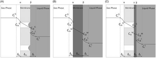
The overall mass transfer resistance based on the liquid phase for a gas-filled microporous membrane is the sum of four resistances in series for gas phase, microporous membrane, biofilm (if applicable), and liquid phase – Equations (11) and (12).
Gas and liquid local mass transfer coefficients depend on the feed flow velocity; on module geometry and dimensions, which determines the thickness of the mass transfer boundary layer; and on the viscosity and the density as these influence the substrate diffusion coefficients. Each local mass transfer coefficient can be estimated using semi-empirical correlations. For and
expressions based on the Sherwood number have been reported – Equations (7) and (8) [Citation28,Citation29].
The gas transport through microporous membranes depends on the pore size range and it can be governed by molecular diffusion or Knudsen (free molecule) diffusion. The effective diffusion coefficient is therefore a function of bulk diffusion and Knudsen diffusion coefficients – EquationEquation (1)(2)
(2) , with the latter depending on the pore diameter of the membrane, molecular mass of the gas, and temperature – EquationEquation (2)
(2)
(2) [Citation30].
(1)
(1)
(2)
(2)
Thus, when the pores are large enough, the interaction with the membrane material can be neglected and the diffusion coefficient in the microporous membrane equals the diffusion coefficient in gas [Citation22].
It has been suggested that the deposition of proteins and cell debris and the presence of surfactants may cause the pore walls to become hydrophilic such that the pores fill with liquid, thereby rendering microporous membranes unsuitable for long-term operation [Citation31].
Dense membranes
Dense or non-porous membranes usually consist of polymers such as silicone, structured by non-continuous passages in the polymer chain matrix [Citation26]. Diffusion occurs in the free volume between the polymer chains [Citation32] and is described by the solution-diffusion model. The concentration profile of a gas species in the case of a dense membrane is shown in .
Like for microporous membranes, for dense membranes the overall mass transfer resistance based on the liquid phase is the sum of each local resistance term – Equations (13) and (14). However, the mass transfer coefficient inside the dense membrane depends on the gas species permeability in the dense membrane and its thickness – Equation (10). The permeability of the gas molecules is controlled by two major parameters: diffusion coefficient and solubility coefficient in the dense membrane (also referred to as gas-membrane partition coefficient).
High gas permeabilities can be achieved in rubbery dense membranes, such as silicones, given their large free volume, due to the flexibility of the siloxane linkages in the polymer [Citation33]. Due to this, syngas compounds (CO, H2, CO2, and N2) are more soluble (two to seven times) in polydimethylsiloxane (PDMS) membrane than in water, although the respective diffusivities are three to four orders of magnitude lower. Dense glassy polymers with high free volume, such as poly(trimethylsilyl)propyne (PTMSP), polymethylpentene (PMP) and Teflon™ AF (a commercial polymer consisting of perfluorinated dioxolane) [Citation34] have intrinsically very high gas permeabilities, showing therefore great potential for the permeation of syngas. Merkel et al. [Citation35] reported extraordinarily high CO, H2, and CO2 permeabilities in a PTMSP dense membrane. Although this is the most permeable polymer known, it is also highly susceptible to fast physical aging, a limitation for long-term operations.
Dense membranes can operate at high transmembrane pressures, up to 3 × 10⁵ Pa in silicone membranes [Citation31]. As a result, a large chemical potential gradient can easily be maintained, causing an increased mass transfer rate [Citation36].
On the other hand, dense membranes, such as silicone membranes, are traditionally thicker (100–400 µm) than microporous membranes [Citation37]. Together with their non-porous nature, this should lead to a higher membrane resistance to mass transfer. Nevertheless, nowadays the manufacturing of PDMS hollow fibers as thin as 20 µm has been reported.
Silicone membranes also offer high resistance to chemical and mechanical stress and, in contrast to microporous membranes, they are not susceptible to pore-clogging (biofouling) or liquid entry in the pores [Citation31].
Asymmetric membranes
Asymmetric membranes consist of an ultra-thin dense layer supported by a porous structure. In integral asymmetric membranes, the dense skin layer and the porous supports are formed from the same material, while composite asymmetric membranes consist of two or more layers from different materials that can be optimized independently [Citation38]. The dense thin top layer selectively permeates compounds while the microporous layer provides mechanical strength. In either case, the liquid is in contact with the dense layer [Citation25]. Gaseous species diffuse through the microporous layer, subsequently solubilize and diffuse through the dense layer, and then enter the liquid at the wetted dense surface [Citation39]. The concentration profile of a gas species in the case of an asymmetric membrane is shown in .
Multi-layer composite membranes contain additional layers of different materials besides a microporous support layer, each with a designated function [Citation39].
Asymmetric membranes combine the advantages of symmetric dense and microporous membranes (cf. microporous membranes), since the porous layer offers support, the ultra-thin dense skin layer provides high permselectivity like dense membranes, but at a lower mass transfer resistance, and neither layer shows high mass transfer resistance. Moreover, they can function at higher pressures than porous membranes without the biofouling and wetting of pores.
For syngas fermentation, where the rate of permeation is more important than permselectivity, the best candidates seem to be asymmetric membranes that offer high permeability for syngas compounds, suitable support for microbial growth (Section “Biofilm formation in HFM bioreactors”) and includes a dense layer with sufficient mechanical stability, such as PDMS or PMP. Further research should focus on novel composite membranes with thin dense non-porous layers able to operate under high transmembrane pressure without a decline in the permeation rates [Citation40].
Membrane module configurations for syngas fermentation
The membrane geometry, flat or tube-shaped, defines the membrane module configuration to be integrated into a bioreactor.
Flat membranes modules are mainly used for laboratory tests because they are easier to build, and sheet replacement is simple and fast. Usually, a single flat sheet is located between two plates that are equipped with the inlets/outlets of both phases. For large interfacial areas, flat membranes are used in plate-and-frame or in spiral-wound modules [Citation25].
In tube-shaped configurations, many membrane tubes or fibers are packed into bundles and potted into tube sheets to form a module. Depending on tube diameter, this can be a tubular (>10 mm), capillary (0.5–10 mm), or hollow fiber (<0.5 mm) module. The membranes divide a module into a lumen-side, which is the space enclosed by the membranes, and a shell-side which is the space between the outer surface of the membranes and the housing [Citation41].
The choice of the module configuration for syngas permeation in a bioreactor should balance several factors such as surface area per unit of liquid volume, membrane manufacturing cost, suitability for high-pressure operation, and fouling control. To guarantee an efficient performance, the module should maximize the mass transfer, reduce and control the fouling, work with low-pressure drops, and have a constant performance over its whole length [Citation25].
For industrial syngas fermentation, the membrane should be packed in an efficient and economical way for maximizing interfacial area per volume unit.
Regarding this aspect, hollow fiber membrane (HFM) modules outcompete other configurations. Furthermore, they entail the lowest membrane manufacturing costs – . This explains why HFM modules are the preferred and most common modules for gas–liquid membrane contacting applications. Consequently, the performance of membrane contactors for syngas fermentation has almost exclusively been studied for HFM modules.
Table 3. Design parameters for membrane module selection. [Citation26].
Hollow fiber membrane bioreactors for syngas fermentation
While the mass transfer coefficient within HFMs depends only on the material, as indicated in Equations (9) and (10), the mass transfer on the shell and lumen sides of an HFM module depends on flow conditions and fiber or module geometries. For this reason, significant efforts have been addressed to the improvement of the HFM material properties, but also to the optimization of packing density, fiber length and diameters, operative flow rates, pressures and concentrations, fluid physical properties, pressure drops, and breakthrough pressure [Citation25].
In HFM modules, non-uniform flow at the shell side of the hollow fiber can occur due to: channeling, bypassing, mixing, entry region phenomena (caused by fiber deformation), non-uniform fiber distribution, the polydispersity of fiber diameters, or presence of stagnant zones [Citation25]. Since this maldistribution of flow leads to a reduction of mass transfer efficiency, much research is dedicated to improving the module design in terms of higher mass transfer coefficients at the shell side. Stanojević et al. [Citation23] reviewed membrane contactor designs and operation, including different innovative types of modules for HFM contactors. One of the main strategies includes: modification of the standard geometry to promote flow perpendicular to the fibers, for example, using woven hollow fiber wound helically around a central core, using woven hollow fiber wound mounted diagonally in a rectangular box, or introduction of baffles in the module [Citation29].
Published lab-scale syngas fermentation studies use commercial membrane modules or custom-built prototypes ( and ). These will be discussed later.
Table 4. Different HFM reactor configurations studied for syngas mass transfer, respective characteristics and the maximum KLa reported.
Table 5. HFM bioreactor configurations for syngas fermentation and respective operational conditions.
Flow configurations and patterns
The distinct flow configurations in HFM reactors and their respective advantages are summarized in .
Table 6. Summary of flow configurations in a hollow fiber membrane reactor and their respective advantages.
For syngas fermentation, the gas feed can enter an HFM module from the shell or lumen side. In lumen/tube-side feed (also known as inside-out) configuration, the gas that is supplied to the lumen of the HFM permeates through the membrane to the fermentation broth or biofilm across the membrane wall. In shell-side feed (outside-in) configuration the fermentation broth circulates inside the lumen of the fibers. Given the small inner diameter of the fibers, typically used for gas–liquid contacting, the outside-in configuration is not advised because biofilm formation in the lumen might block broth flow. Therefore, in the field of syngas fermentation, this configuration has been mainly tested for abiotic gas–liquid mass transfer measurements [Citation13].
In terms of gas supply and depending on their design and fabrication, HFM modules can be operated in a dead-end or open-end configuration. In an open-end configuration, both ends of the fiber bundle tube sheets are open. For lumen-side feeding, this implies that the gas feed is supplied from one end of the bundle, and the retentate exits from the opposite end. If gas is not recycled, inherently this configuration leads to a lower extent of gas conversion since there is loss of syngas substrate with the gaseous retentate. On the other hand, the gas velocity throughout the membrane is usually high. Therefore, the advective mass transport in the lumen is much faster than the diffusive transfer across the membrane, which results in relatively uniform syngas concentrations in the lumen, leading to high average fluxes [Citation56].
In a closed-end configuration, the fiber bundles are sealed at one end [Citation14,Citation44] or are looped back to form a “U” shape in the bundle [Citation53]. All the gas supplied to the membranes is delivered through the membrane fiber, allowing 100% extent of syngas transfer [Citation14]. However closed-end HFM are usually susceptible to gas back-diffusion where produced CO2 diffuses into the membrane lumen, which lowers the transfer rate of CO and H2 [Citation56]. Furthermore, in HFMs for a gas transfer, there is also the risk of water condensation in the HFM lumen. This problem can be caused by the supply of dry feed gas at the temperature of the aqueous fermentation medium [Citation57,Citation58]. Since the gas permeable membranes are also highly permeable to water, the gas inside the hollow fibers becomes saturated by water within a few centimeters from the gas feed entrance. Therefore a closed-end HFM should be designed such that the condensate and lumen gases are vented [Citation57]. Perez-Calleja et al. [Citation56] have stated that periodic venting of the lumen of the HFM has great potential to improve the gas transfer rate and extent, increasing the performance of the HFM module and decreasing the capital and operational costs. Steady-state operation of an open-end system with minimized gas outflow could be an equivalent option.
Depending on the relative flow directions of the two fluid phases, HFM modules can be classified as longitudinal/axial-flow (operated either counter-current or co-current) or as cross-flow. An axial flow pattern is often achieved in parallel hollow fiber bundles. Perez-Calleja et al. [Citation56] reported higher dissolved gas concentrations toward the end of the membrane fiber when operating in co-current mode. Cross-flow is designed to provide a perpendicular flow to the membrane surface, which results in a higher mass transfer coefficient than that achieved with the parallel flow. The radial flow pattern can be imposed by using, for example, an HFM module with a perforated central tube to deliver the liquid feed to the shell-side, a helically wound bundle, or by introducing flow diverters and baffles in the HFM module design – .
Figure 3. HFM modules with (A) tubesheets at both ends; (B) a single tubesheet in a U shaped bundle; (C) one tubesheet and one sealed end; (D, E) gas feed entering the bundle from the perforations on the central tube and exiting from (D) the port on the housing or (E) the perforations toward the other end; (F) Baffles with alternating clearances at top and bottom to force the flow up and down. Based on [Citation41].
![Figure 3. HFM modules with (A) tubesheets at both ends; (B) a single tubesheet in a U shaped bundle; (C) one tubesheet and one sealed end; (D, E) gas feed entering the bundle from the perforations on the central tube and exiting from (D) the port on the housing or (E) the perforations toward the other end; (F) Baffles with alternating clearances at top and bottom to force the flow up and down. Based on [Citation41].](/cms/asset/1a8f6192-e0d0-45ce-a38c-4e4e65be5372/ibty_a_1965952_f0003_b.jpg)
Side-stream and submerged HFMs
In stand-alone HFM modules, the liquid has a plug flow behavior, whereas liquid mixing is required to achieve pH control such as is necessary for most industrial fermentations. Thus, in case high-performance fermentation is desired, the liquid is circulated through a mixed compartment. The HFM module can be submerged in a mixed bioreactor (internal module) or can be coupled with an external mixed tank. In the internal configuration, the HFM bundle is fabricated as an integral part of the fermentation vessel or submerged in the fermentation broth. In these systems, liquid mixing can be achieved by using a microporous membrane as a gas micro-diffuser, designated as a hollow fiber membrane bubble column reactor (HFM-BCR) [Citation43,Citation44]. This is also achieved by the implementation of impellers in the reactor [Citation55], or the addition of a liquid recirculation circuit [Citation10,Citation59].
In the external configuration, the fermentation broth is circulated between the HFM module and a reservoir tank. This configuration is inherently very flexible, allowing the connection of available commercial modules to the external tank, therefore being investigated in several laboratory studies (). The fermentation broth is commonly supplied to the shell side of the membrane module and the liquid velocity entering the module is controlled by a cross-flow pump. If the external vessel is a stirred tank, the rotor can be used for additional mixing of the fermentation broth. The pump settings and tube sizing should be selected to minimize the shear stress induced on the microorganisms. The liquid feed, containing nitrogen source and mineral medium, is supplied to the external tank. Depending on the configuration and simplicity of the external tank, sensors can be installed, and the pH, temperature, and level of the broth can be controlled. Nonvolatile products are collected from the tank effluent. For simplicity, laboratory setups can use an overflow bottle as the external reservoir [Citation59]. Both configurations have been tested in liquid batch, in sequential batch, or continuous configuration mode (). Gas delivery to the reactor is always continuous.
Mass transfer under abiotic conditions
The typical approach to evaluate syngas to liquid mass transfer performance in HFM bioreactors is the design of experiments to measure, directly or indirectly, the dissolved gas concentrations in the liquid, in the absence of cells and biochemical conversion, and determine the mass transfer coefficients of the system from this concentration. The volumetric mass transfer coefficient, KLa, is not only useful to compare mass transfer capacity of different setups and at different operational conditions, but also to provide valuable information for the reactor design or process modeling. Different HFM bioreactor configurations for the permeation of syngas substrates under abiotic conditions have been tested at laboratory scale and the respective KLa values have been reviewed, although not all literature values can be directly compared [Citation14,Citation42]. Therefore, a detailed explanation is discussed here. The approach to calculate KLa is highly dependent on the configuration and characteristics of the reactor (mixed external reservoir vessel, submerged in a reactor or stand-alone) and on the method and experimental design used.
In mass transfer studies with HFM modules including an external liquid recirculation configuration, the following equation applies in case of a liquid concentration gradient over the fiber length with no concentration gradients at the gas side.
(3)
(3)
C*, C0, and CL are, respectively, the saturated concentration, the initial concentration, and actual concentration of dissolved gas in the aqueous phase in the reservoir tank (assuming well-mixed conditions), QL is the liquid recirculation rate through the membrane module, VR is the working volume of the reservoir tank vessel, KL the overall mass transfer coefficient, and according to the derivation of Ahmed and Semmens [Citation37], a is the volume-specific interfacial area of the membrane module (per liquid volume in the membrane module), L is the hollow fiber length, vL is the liquid velocity in the HFM module and t is the sampling time. Then, KLa for gas is determined by a dynamic method. During batch operation, the transient dissolved gas concentration in the well-mixed liquid reservoir is periodically measured and plotted against the sampling time according to EquationEquation (3)
(3)
(3) . KLa is obtained from the slope of this linear relation. EquationEquation (3)
(3)
(3) can be rearranged to the exponential form to reduce errors resulting from linear regression.
Since KLa according to EquationEquation (3)(3)
(3) is calculated per liquid volume in the membrane module solely, it must be recalculated when accounting for the total working volume of the bioreactor, VL, that is, the external reservoir working volume, VR, in addition to the membrane module liquid volume, VM.
If the characteristic time for liquid recirculation (VR/QL) is much shorter than the characteristic time for mass transfer (1/KLa), EquationEquation (3)(3)
(3) simplifies to EquationEquation (4)
(4)
(4) as follows:
(4)
(4)
Consequently, there is no concentration gradient along the fibers. This condition has been achieved at submerged HFM reactor configurations, for which KLa can similarly be determined by a dynamic method according to EquationEquation (5)(5)
(5) [Citation10,Citation43,Citation44].
(5)
(5)
For stand-alone HFM reactors, KLa has been calculated by a steady-state mass transfer analysis (static method) according to EquationEquation (6)(6)
(6) [Citation11,Citation42].
(6)
(6)
This applies to HFM reactors in a steady state in which there are gradients along the gas side as well as the liquid side of the fiber axis, but with no gradients perpendicular to the axis.
KLa is based on membrane module liquid volume, VM, CL,out is the quasi-steady-state concentration of dissolved gas in the liquid outlet, and ΔClm is the logarithmic mean dissolved concentration difference between saturated liquid (at the partial pressure of the gas) and liquid phase (calculated differently depending on co-current or counter-current flow operation).
The KLa values in differ by three orders of magnitude and should be compared with caution given the different methodologies used for their calculation, the different volumes considered (total reactor working volume or solely liquid volume of the membrane module), and the different operational parameters used in distinct experimental setups [Citation11,Citation16]. It is crucial to report these factors in detail, particularly the HFM module volume, total system volume, and volume used to calculate the KLa [Citation42].
Syngas fermentation performance in HFM reactors
Pure cultures
A minority of studies mentioned in investigated HFMs submerged in bubble column reactors [Citation43,Citation44]. Yasin et al. [Citation43] investigated the fermentation of a mixture of CO/CO2 by Eubacterium limosum KIST612, which yielded acetate, and as by-products butyric and isobutyric acids with trace amounts of ethanol and 1-butanol. The liquid phase was operated in batch mode, whereas the syngas was continuously supplied through the hydrophobic microporous hollow fibers (closed-end), resulting in the formation of bubbles on the liquid side. In these types of systems, the HFM is used as a micro-sparger of the syngas substrates, and micro-bubbles delivered by the membrane not only contribute to KLa but also to liquid mixing and to reduced gas retention in the liquid. Jang et al. [Citation44] used an analogous experimental setup to study the effect of electrolyte addition to the medium on CO mass transfer to the liquid and on biomass, ethanol, and acetate production. This study utilized Clostridium autoethanogenum DSM10061 for the fermentation of CO/CO2 (80:20) supplied via submerged microporous HFMs, with recirculation of the headspace gas. Addition of 1% MgSO4 increased ethanol productivity, ethanol concentration, cell concentration and ethanol/acetate ratio. This was explained by a mass transfer increase due to bubble coalescence suppression in the presence of an electrolyte.
Other studies with pure cultures investigated HFM biofilm reactors coupled with an external reservoir. Shen et al. [Citation24] tested an HFM module made of microporous hydrophobic polypropylene coupled with an agitated reservoir vessel for the continuous fermentation of syngas (20% CO, 5% H2, 15%, CO2, and 60% N2) to ethanol and acetate and characterized fermentation performance at different syngas flow, liquid recirculation and dilution rates. A modest ethanol concentration of 23.93 g L−1 and ethanol to the acetic acid molar ratio of 4.79 was achieved for a liquid recirculation of 200 ml min−1, a dilution rate of 0.12 day−1 and for a syngas flow of 300 and 200 ml min−1, respectively. Yet, this is the highest titer achieved for this type of reactor configuration and comparable to published data for reactors employing gas bubbling [Citation24]. The maximum ethanol productivity of 3.44 g L−1 day−1 was reported at a different dilution rate (0.96 day−1). The authors reported the formation of a biofilm on the membrane surface but did not quantify mass or thickness. The formation of the biofilm proved to be beneficial as a cell retention method, as it was possible to grow the microorganism at a dilution rate higher than reported in suspended growth syngas fermentation reactors using the same strain [Citation24].
Anggraini et al. [Citation48] compared the performance of liquid batch syngas fermentation in an STR with and without an HFM integration, concluding that higher ethanol yield, ethanol titer, and ethanol-acetate ratio can be achieved in the former due to an increase in syngas mass transfer rates.
Abubackar et al. [Citation9] reviewed a number of HFM reactor configurations patented for syngas fermentation. Tsai et al. [Citation54], for example, showed the usefulness of an asymmetric HFM module that retained the cells as a biofilm layer in the membrane pores (shell side), of approximately 400 μm. The syngas stream was fed to the shell side while ethanol and other products formed in the membrane pore biofilm were transferred through the membrane (hydration layer) to the liquid medium, which recirculated between the fiber’s lumen and an external stirred reservoir. With this configuration, Clostridium ragsdalei produced 15 g L−1 ethanol after 20 days of continuous operation.
Mixed cultures
also includes studies that coupled HFMs with external reservoirs for the mixed culture fermentation of syngas to carboxylic acids or methane. Operational conditions tested include membrane interfacial area, syngas composition, continuous or batch liquid operation mode, temperature, and pH. Shen et al. [Citation52] investigated the conversion of CO/H2 (40:60) by mixed culture in a closed-end HFM biofilm reactor by varying the: membrane surface area, liquid operation mode, and temperature. The main products obtained for a sequential batch experiment at 35 °C were: acetate, butyrate, hexanoate, and octanoate. The main product at 55 °C was acetate (minimal butyrate detected), at a maximal concentration and productivity of 24.6 g L−1 and 16.4 g L−1 day−1, respectively, for the continuous liquid operation of the reactor. More membrane area per working volume, hence higher available mass transfer area, led to increased production [Citation52]. Clostridium and Thermoanaerobacterium strains played major roles in this at 35 and 55 °C. In mixed culture fermentation of carbon dioxide and hydrogen, again acetate was the major product [Citation49,Citation50,Citation53]. Wang et al. [Citation53] achieved the highest acetate titers (42.0 g L−1) in a mixed culture HFM biofilm reactor, converting CO2 and H2 (40:60) in a liquid batch operation at 55 °C. Continuous liquid flow operation was also tested, reaching lower titers but acetate productivity up to 10.5 g L−1 day−1 at a hydraulic retention time (HRT) of 1 day.
Luo et al. [Citation55] tested biogas production in an HFM reactor for simultaneous continuous sewage sludge treatment and CO biomethanation at 55 °C. Complete consumption of CO was reported, with maximal productivity of methane of 1992 ml L−1 d−1. The microorganisms mainly responsible for CO biomethanation were distributed differently in the liquid and in the biofilm formed on the HFM. The efficiency of microporous membranes used for the CO supply to the liquid was reported to be limited due to its relatively low bubble point pressure [Citation55].
Biofilm formation in HFM bioreactors
As HFM bioreactors can support biofilm formation, this phenomenon needs attention. Biofilms are microbial consortia composed of one or more types of cells adhering to each other or to a surface, enclosed in a matrix of extracellular polymeric substances (EPS). Biofilm formation is linked to quorum sensing, a cell-to-cell communication mechanism via self-produced extracellular chemical signals, which allows microorganisms to monitor the population density and regulate gene expression accordingly [Citation60].
Depending on the hydrodynamic conditions achieved in the HFM, and the propensity of the microbial culture to form biofilms or to attach to the membrane material, a biofilm can form in the outer layer of the membrane and cell retention in the module can be achieved. For a liquid continuous operation, the biofilm attached to the membrane surface continues to grow until the biofilm reaches a thickness equilibrated with the operating conditions [Citation61]. This membrane biofilm reactor is typically known as a counter-diffusional biofilm operation, that is, when the substrate (electron donor or acceptor) diffuses through the membrane toward a biofilm naturally forming on the membrane outer surface, while complementary substrates or nutrients typically diffuse from the bulk liquid into the biofilm [Citation62]. Product usually diffuses to the bulk liquid, but depending on membrane characteristics, the volatile product can also diffuse to the lumen of hollow fibers. In that case, it would be stripped with the gas feed (in an open fiber configuration) or achieve equilibrium in a closed-end fiber.
Biofilm reactors can offer several advantages in comparison with planktonic cell configurations as they can enable higher cell density and stability. This can lead to higher volume-specific productivity, long-term continuous operation at high dilution rates without cell wash-out, and easier downstream processing [Citation63]. Moreover, the biofilm offers a confined microenvironment that might protect cells from inhibitory compounds, substrates, or products [Citation63,Citation64].
An understanding of biofilm formation and composition is essential for the design and optimization of biofilm-based processes [Citation63], although limited knowledge is available for anaerobic syngas-fermenting microorganisms. Philips et al. [Citation65] observed that the addition of NaCl (200 mmol L−1) to their growth medium strongly induced biofilm formation as a stress response of Clostridium ljungdahlii, a well-known syngas fermenting bacterium. The biofilm matrix was composed of extracellular proteins, polysaccharides, and DNA. Several other Clostridium species, including syngas fermenting bacteria, are also known to be capable of biofilm formation [Citation66]. As shown in , biofilms have been formed in HFMs for syngas fermentation by Clostridium carboxidivorans P7, Clostridium ljungdahlii, and Carboxydothermus hydrogenoformans, although biofilm density (usually defined as the biomass concentration in the biofilm), biofilm thickness, molecular composition, or mechanical properties were not fully characterized. Shen et al. [Citation24] concluded that liquid recirculation rates through the membrane module are crucial for the fermentation performance, as it is responsible for maintaining an appropriate thickness of the biofilm in the module. A high recirculation rate corresponds to high shear stress and results in biofilm abrasion, while a low recirculation rate tends to cause membrane biofouling in the HFM reactor. Zhao et al. [Citation47] observed heterogeneous colonization of the membrane and mushroom-shaped micro-colonies in the most populated regions of the fibers, typical of biofilms grown under low laminar flow conditions. The irregular radial biofilm distribution was related to the possibly uneven fiber packing in the module causing an irregular flow of liquid and substrate and nutrient maldistribution. Moreover, EPS accounted for 14% of the total attached biomass.
Syngas transfer to biofilm requires the use of large membrane areas while the membrane modules need to accommodate a desired volume of biofilm. Therefore, the challenge with HFM biofilm reactors is to achieve and control biomass accumulation on properly dimensioned membrane units that contain well-performing membrane materials [Citation57].
Comparison with commercial syngas bioreactors
Membrane bioreactors and the current industrial-scale gas-lift bioreactors should be compared on syngas fermentation potential. However, no full-scale process data or conceptual studies at comparable operational conditions (syngas composition, pH, and temperature), the scale of the reactor, and microbial strain are available, as the only current commercial process is owned and protected by LanzaTech. From industrial data, a maximum mass transfer coefficient (KLa) of 374 h−1 has been estimated for CO in bubble columns for a superficial gas velocity of 0.14 m s−1 [Citation67]. Higher gas flow rates, lower pressure, and non-coalescing media could increase this value. On the other hand, values up to 1096 h−1 are found for lab-scale HFM reactors (), and such KLa values will not be scale-dependent in the case of modular scale-up of HFM reactors. Thus, HFM reactors need a smaller volume for transferring the same amount of syngas.
Exploiting high KLa values requires operation at high biomass concentration. At steady-state operation, HFM reactors with biofilms need little cell growth, whereas gas-lift reactors and bubble columns need either substantial cell growth or cell retention systems, for similar performance. Estimates of costs involved in this are not available.
Per m3, bubble column costs should decrease with increasing size because of decreasing area/volume ratio. HFM reactor costs per m3 are determined by membrane costs and membrane area per volume. Since this will not show many dependencies on the scale, HFM reactors become less likely to be competitive if very large production volumes are needed such as in the case of bulk products like ethanol. Fine chemicals may be a better target for HFM reactors.
Conclusions and future perspectives
The technical feasibility of membrane modules for syngas permeation and fermentation has been demonstrated at the laboratory scale. They can offer cell retention and high syngas mass transfer, potentially leading to high productivities. To achieve this, HFM modules with dense or asymmetric membranes such as PDMS or PMP, respectively, appear suitable. Gas feed configurations (open-/closed-end) and liquid pattern configurations (co-/counter-/cross-current) in these modules have not been systematically studied. Liquid flow operations, though, should prevent biofouling of the module while maximizing mass transfer rates. In the case of external liquid recirculation, external volumes should be minimized to avoid volumetric mass transfer losses. Comparison of published mass transfer performances of HFM reactors for syngas permeation is not straightforward given the variability between the setup, operational conditions, and calculation methodologies.
The economic feasibility of membrane modules for syngas supply in fermentation is not yet clear, because it requires prior process optimization. However, the number of design parameters is large; they are related to:
Mass transfer kinetics (membrane permeabilities, KLa determination, and standardization)
Reaction kinetics and stoichiometry
Biofilm kinetics (cell growth and detachment)
Using mathematical models would allow a more systematic design and optimization of HFM reactors and an understanding of each variable’s contribution to the overall performance.
Disclosure statement
No potential conflict of interest was reported by the author(s).
Additional information
Funding
References
- Phillips JR, Huhnke RL, Atiyeh HK. Syngas fermentation: a microbial conversion process of gaseous substrates to various products. Fermentation. 2017;3(2):28.
- Daniell J, Köpke M, Simpson S. Commercial biomass syngas fermentation. Energies. 2012;5(12):5372–5417.
- Takors R, Kopf M, Mampel J, et al. Using gas mixtures of CO, CO2 and H2 as microbial substrates: the dos and don’ts of successful technology transfer from laboratory to production scale. Microb Biotechnol. 2018;11(4):606–625.
- Köpke M, Simpson SD. Pollution to products: recycling of ‘above ground’ carbon by gas fermentation. Curr Opin Biotechnol. 2020;65:180–189.
- Redl S, Diender M, Jensen TØ, et al. Exploiting the potential of gas fermentation. Ind Crops Prod. 2017;106:21–30.
- Bengelsdorf FR, Beck MH, Erz C, et al. Bacterial anaerobic synthesis gas (syngas) and CO2+H2 fermentation. In: Sariaslani S, Gadd GM, editors. Advances in applied microbiology. Vol. 103. Cambridge (MA): Academic Press; 2018. p. 143–221.
- Liew F, Martin ME, Tappel RC, et al. Gas fermentation-a flexible platform for commercial scale production of low-carbon-fuels and chemicals from waste and renewable feedstocks. Front Microbiol. 2016;7:694.
- Straathof AJJ. Transformation of biomass into commodity chemicals using enzymes or cells. Chem Rev. 2014;114(3):1871–1908.
- Abubackar HN, Veiga MC, Kennes C. Biological conversion of carbon monoxide: rich syngas or waste gases to bioethanol. Biofuels, Bioprod Bioref. 2011;5(1):93–114.
- Munasinghe PC, Khanal SK. Syngas fermentation to biofuel: evaluation of carbon monoxide mass transfer coefficient (kLa) in different reactor configurations. Biotechnol Prog. 2010;26(6):1616–1621.
- Orgill JJ, Atiyeh HK, Devarapalli M, et al. A comparison of mass transfer coefficients between trickle-bed, hollow fiber membrane and stirred tank reactors. Bioresour Technol. 2013;133:340–346.
- Bredwell MD, Srivastava P, Worden RM. Reactor design issues for synthesis-gas fermentations. Biotechnol Prog. 1999;15(5):834–844.
- Munasinghe PC, Khanal SK. Syngas fermentation to biofuel: evaluation of carbon monoxide mass transfer and analytical modeling using a composite hollow fiber (CHF) membrane bioreactor. Bioresour Technol. 2012;122:130–136.
- Yasin M, Jeong Y, Park S, et al. Microbial synthesis gas utilization and ways to resolve kinetic and mass-transfer limitations. Bioresour Technol. 2015;177:361–374.
- Ebrahimi S, Kleerebezem R, Kreutzer MT, et al. Potential application of monolith packed columns as bioreactors, control of biofilm formation. Biotechnol Bioeng. 2006;93(2):238–245.
- Asimakopoulos K, Gavala HN, Skiadas IV. Reactor systems for syngas fermentation processes: a review. Chem Eng J. 2018;348:732–744.
- Ylitervo P, Akinbomi J, Taherzadeh MJ. Membrane bioreactors’ potential for ethanol and biogas production: a review. Environ Technol. 2013;34(13–16):1711–1723.
- Charcosset C. Membrane processes in biotechnology: an overview. Biotechnol Adv. 2006;24(5):482–492.
- Yang M-C, Cussler EL. Designing hollow-fiber contactors. AIChE J. 1986;32(11):1910–1916.
- Kartohardjono S, Chen V. Mass transfer and fluid hydrodynamics in sealed end hydrophobic hollow fiber membrane gas-liquid contactors. J Appl Membr Sci Technol. 2005;2(1):1–12.
- Kumar A, Dewulf J, Van Langenhove H. Membrane-based biological waste gas treatment. Chem Eng J. 2008;136(2–3):82–91.
- Reij MW, Keurentjes JTF, Hartmans S. Membrane bioreactors for waste gas treatment. J Biotechnol. 1998;59(3):155–167. doi:(97)00169-7.
- Stanojević M, Lazarević B, Radić D. Review of membrane contactors designs and applications of different modules in industry. FME Transact. 2003;31(2):91–98.
- Shen Y, Brown R, Wen Z. Syngas fermentation of clostridium carboxidivoran P7 in a hollow fiber membrane biofilm reactor: evaluating the mass transfer coefficient and ethanol production performance. Biochem Eng J. 2014;85:21–29.
- Drioli E, Criscuoli A, Curcio E. Membrane contactors: fundamentals, applications and potentialities. Vol. 11. Amsterdam (The Netherlands): Elsevier; 2006.
- Ismail AF, Khulbe KC, Matsuura T. Gas separation membranes. Vol. 7. New York (NY): Springer; 2015.
- Zhou H, Jin W. Membranes with intrinsic micro-porosity: structure, solubility, and applications. Membranes. 2018;9(1):3.
- Zhao S, Feron PHM, Deng L, et al. Status and progress of membrane contactors in post-combustion carbon capture: a state-of-the-art review of new developments. J Membr Sci. 2016;511:180–206.
- Gabelman A, Hwang S-T. Hollow fiber membrane contactors. J Membr Sci. 1999;159(1–2):61–106.
- Feron PHM, Jansen AE. CO2 separation with polyolefin membrane contactors and dedicated absorption liquids: performances and prospects. Sep Purif Technol. 2002;27(3):231–242.
- Casey E, Glennon B, Hamer G. Review of membrane aerated biofilm reactors. Resour Conserv Recycl. 1999;27(1–2):203–215. doi:(99)00007-5.
- Mallevialle J, Odendaal PE, Wiesner MR, et al. Water treatment membrane processes. New York (NY): McGraw-Hill; 1996.
- Sridhar S, Smitha B, Aminabhavi TM. Separation of carbon dioxide from natural gas mixtures through polymeric membranes—a review. Separat Purific Rev. 2007;36(2):113–174.
- Resnick PR, Buck WH. Teflon® AF: a family of amorphous fluoropolymers with extraordinary properties. In: Hougham G, Cassidy PE, Johns K, editors. Fluoropolymers 2: properties. Boston (MA): Springer US; 1999. p. 25–33.
- Merkel TC, Gupta RP, Turk BS, et al. Mixed-gas permeation of syngas components in poly(dimethylsiloxane) and poly(1-trimethylsilyl-1-propyne) at elevated temperatures. J Membr Sci. 2001;191(1–2):85–94. doi:(01)00452-5.
- Voss MA, Ahmed T, Semmens MJ. Long-term performance of parallel-flow, bubbleless, hollow-fiber-membrane aerators. Water Environ Res. 1999;71(1):23–30.
- Ahmed T, Semmens MJ. Use of sealed end hollow fibers for bubbleless membrane aeration: experimental studies. J Membr Sci. 1992;69(1–2):1–10.
- Wang Z, Dong S, Li N, et al. CO2-selective membranes: how easy is their moving from laboratory to industrial scale? In: Basile A, Favvas EP, editors. Current trends and future developments on (bio-) membranes. Amsterdam (The Netherlands): Elsevier; 2018. p. 75–102.
- Pinnau I. MEMBRANE SEPARATIONS | membrane preparation. In: Wilson ID, editor. Encyclopedia of separation science. Oxford (UK): Academic Press; 2000. p. 1755–1764.
- Bazhenov DS, Bildyukevich VA, Volkov VA. Gas-liquid hollow fiber membrane contactors for different applications. Fibers. 2018;6(4):76.
- Wan CF, Yang T, Lipscomb GG, et al. Design and fabrication of hollow fiber membrane modules. J Membr Sci. 2017;538:96–107.
- Orgill JJ, Abboud MC, Atiyeh HK, et al. Measurement and prediction of mass transfer coefficients for syngas constituents in a hollow fiber reactor. Bioresour Technol. 2019;276:1–7.
- Yasin M, Park S, Jeong Y, et al. Effect of internal pressure and gas/liquid interface area on the CO mass transfer coefficient using hollow fibre membranes as a high mass transfer gas diffusing system for microbial syngas fermentation. Bioresour Technol. 2014;169:637–643.
- Jang N, Yasin M, Kang H, et al. Bubble coalescence suppression driven carbon monoxide (CO)-water mass transfer increase by electrolyte addition in a hollow fiber membrane bioreactor (HFMBR) for microbial CO conversion to ethanol. Bioresour Technol. 2018;263:375–384.
- Ferreira BS, Fernandes HL, Reis A, et al. Microporous hollow fibres for carbon dioxide absorption: mass transfer model fitting and the supplying of carbon dioxide to microalgal cultures. J Chem Technol Biotechnol. 1998;71(1):61–70.
- Lee P-H, Ni S-Q, Chang S-Y, et al. Enhancement of carbon monoxide mass transfer using an innovative external hollow fiber membrane (HFM) diffuser for syngas fermentation: experimental studies and model development. Chem Eng J. 2012;184:268–277.
- Zhao Y, Haddad M, Cimpoia R, et al. Performance of a Carboxydothermus hydrogenoformans-immobilizing membrane reactor for syngas upgrading into hydrogen. Int J Hydrogen Energy. 2013;38(5):2167–2175.
- Anggraini ID, Keryanti M, Purwadi R, et al. Bioethanol production via syngas fermentation of Clostridium ljungdahlii in a hollow fiber membrane supported bioreactor. IJTech. 2019;10(3):481–490.
- Zhang F, Ding J, Zhang Y, et al. Fatty acids production from hydrogen and carbon dioxide by mixed culture in the membrane biofilm reactor. Water Res. 2013;47(16):6122–6129.
- Zhang F, Ding J, Shen N, et al. In situ hydrogen utilization for high fraction acetate production in mixed culture hollow-fiber membrane biofilm reactor. Appl Microbiol Biotechnol. 2013;97(23):10233–10240.
- Wang H-J, Dai K, Xia X-Y, et al. Tunable production of ethanol and acetate from synthesis gas by mesophilic mixed culture fermentation in a hollow fiber membrane biofilm reactor. J Cleaner Prod. 2018;187:165–170.
- Shen N, Dai K, Xia X-Y, et al. Conversion of syngas (CO and H2) to biochemicals by mixed culture fermentation in mesophilic and thermophilic hollow-fiber membrane biofilm reactors. J Cleaner Prod. 2018;202:536–542.
- Wang Y-Q, Yu S-J, Zhang F, et al. Enhancement of acetate productivity in a thermophilic (55 °C) hollow-fiber membrane biofilm reactor with mixed culture syngas (H2/CO2) fermentation. Appl Microbiol Biotechnol. 2017;101(6):2619–2627.
- Tsai S-P, Datta R, Basu R, et al. inventors; Synata Bio Inc., assignee. Syngas conversion system using asymmetric membrane and anaerobic microorganism. US patent 8,329,456 B2. 2012.
- Luo G, Wang W, Angelidaki I. Anaerobic digestion for simultaneous sewage sludge treatment and CO biomethanation: process performance and microbial ecology. Environ Sci Technol. 2013;47(18):10685–10693.
- Perez-Calleja P, Aybar M, Picioreanu C, et al. Periodic venting of MABR lumen allows high removal rates and high gas-transfer efficiencies. Water Res. 2017;121:349–360.
- Semmens MJ. Alternative MBR configurations: using membranes for gas transfer. Desalination. 2008;231(1–3):236–242.
- Fang Y, Novak PJ, Hozalski RM, et al. Condensation studies in gas permeable membranes. J Membr Sci. 2004;231(1–2):47–55.
- Chen H, Zhao L, Hu S, et al. High-rate production of short-chain fatty acids from methane in a mixed-culture membrane biofilm reactor. Environ Sci Technol Lett. 2018;5(11):662–667.
- Whiteley M, Diggle SP, Greenberg EP. Progress in and promise of bacterial quorum sensing research. Nature. 2017;551(7680):313–320.
- Hickey R, Datta R, Tsai S-P, et al. inventors; Synata Bio Inc., assignee. Membrane supported bioreactor for conversion of syngas components to liquid products. US patent 8,828,692. 2014.
- Nerenberg R. The membrane-biofilm reactor (MBfR) as a counter-diffusional biofilm process. Curr Opin Biotechnol. 2016;38:131–136.
- Zetty Arenas AM. Towards enhanced second-generation n-butanol production from sugarcane [doctoral thesis]. Delft (The Netherlands): Delft University of Technology; 2019.
- Wang Z-W, Chen S. Potential of biofilm-based biofuel production [journal article. Appl Microbiol Biotechnol. 2009;83(1):1–18.
- Philips J, Rabaey K, Lovley DR, et al. Biofilm formation by Clostridium ljungdahlii is induced by sodium chloride stress: experimental evaluation and transcriptome analysis. PLoS One. 2017;12(1):e0170406.
- Pantaléon V, Bouttier S, Soavelomandroso AP, et al. Biofilms of clostridium species. Anaerobe. 2014;30:193–198.
- Almeida Benalcázar E, Noorman H, Maciel Filho R, et al. Modeling ethanol production through gas fermentation: a biothermodynamics and mass transfer-based hybrid model for microbial growth in a large-scale bubble column bioreactor. Biotechnol Biofuels. 2020;13(1):59.