
 ?Mathematical formulae have been encoded as MathML and are displayed in this HTML version using MathJax in order to improve their display. Uncheck the box to turn MathJax off. This feature requires Javascript. Click on a formula to zoom.
ABSTRACT
This paper presents assessments performed on a large database of virgin material and irradiated material thermal creep data from uniaxial and pressurised DIN 1.4970 Ti-stabilised austenitic stainless steel i.e. EN X10NiCrMoTiB15–15 or ‘15-15Ti’ cladding tubes. The data base incorporates multi-heat data from uniaxial and bi-axial (internal pressure) creep tests conducted during the fast reactor R&D program of the DeBeNe (Deutschland-Belgium-Netherlands) consortium between the 1960s to the late 1980s together with more recent data, for example, from the European projects MATTER and PATRICIA and the EERA JPNM pilot project TASTE. The data comprises of a virgin material data base and a data base with irradiated creep data. The virgin material data comprises of time-to-rupture and time-to-0.2% creep strain in a temperature range of 600–800°C and covers a large range of stresses. The irradiated data base has less data and does not cover all material heats tested for the virgin material properties. The irradiation conditions are also different depending on the test reactor specifics and the irradiation campaign targets. The attained ‘irradiation damage’ in displacements per atom (DPA) for the irradiated materials range from 0.1 up to 38.1. Un-irradiated ‘reference material’ models for tensile strength and creep strength are constructed from the current-state of the art literature data and more recent results from the Sandvik 24% cold worked 1515–Ti cladding tube currently used as the main material batch studied at SCK CEN. The tensile strength model is used throughout the paper for normalizing creep strengths by the tensile properties, needed when applying the Wilshire (WE) creep model. Time factors (TF), stress factors (SF) and temperature ratio factors (TRF) are calculated for different material states for describing the impact of heat treatments, (virgin and irradiated) and irradiation conditions. This initial study targets to give estimates for the thermal creep properties of cladding tubes with a cold work range of 16–24% in a non-annealed state, as it is the preferred option for future designs according to the state-of-the art knowledge base. However, the main bulk of the available data on irradiated material is on claddings with a cold work range of 0-16% with and without annealing and at various levels of irradiation damage, thus leading to the need for estimation by interpolation and extrapolation assuming that irradiation damage levels and trends, e.g. time reduction factors found on a lower cold worked material can also be applied on materials with higher cold work levels. The results of the assessments clearly show relative strength differences between chosen material heats and heat treatments and has enabled constructing simple multilinear models for estimating the life of irradiated material. The models show that low creep test temperatures (and irradiation temperatures), low stress levels, low levels of cold work and high irradiation doses are increasing the detrimental difference between the specific material condition and the reference material. Also, it was found that the general level of life reduction (time factor TF and stress factor SF) for irradiation damaged material failure, in relation to the reference material failure, roughly coincides the corresponding values of time to 0.2% creep strain for virgin material. The estimated ‘failure creep temperature limits’ for 30 000 hours of service are studied and compared for both virgin and irradiated materials at a reference stress level of 1/3 of the tensile strength (at temperature).
Introduction
The determination of material properties for materials used for nuclear components are in many cases rare to come by, and the determination of the irradiation effect for a new material is extremely costly, especially for thermal creep properties due to the needed long exposure times in research reactors using dedicated test rigs and rigorous safety analysis requirements. The reuse of historical data is therefore of great value when building up a knowledge base for specific applications. Material performance limits in irradiation exposure are essential for design of nuclear installations [Citation1].
In reactor service fuel cladding tubes are subject to thermal creep at high temperatures due to a difference between the external and internal pressures and loads initiated by possible pellet-clad mechanical interactions (PCMI). In addition the material is under constant neutron irradiation altering the material properties. The assessments performed are mainly based on a large database of virgin material and irradiated material thermal creep data from uniaxial and pressurised DIN 1.4970 Ti-stabilised austenitic stainless steel (i.e. EN X10NiCrMoTiB15–15 or ‘15-15Ti’) cladding tubes [Citation2,Citation3]. The virgin material data set has been assessed earlier [Citation4] and is now studied in greater detail together with irradiated material data. Initial results of the irradiation effect in post-irradiation and in-pile has previously been studied in [Citation5]. The updated data base incorporates multi-heat data from uniaxial and bi-axial (internal pressure) creep tests conducted during the fast reactor R&D program of the DeBeNe (Deutschland-Belgium-Netherlands) consortium between the 1960’s to the late 1980’s together with more recent data, e.g. from the European projects MATTER [Citation4], the currently ongoing PATRICIA and the EERA JPNM pilot project TASTE [Citation6,Citation7].
The purpose of this paper is to apply the current state-of-the-art (SOTA) assessment methods successfully used for determining no- and negligible creep temperatures [Citation8,Citation9] (for the use in the standard EN 13,445–3 [Citation10]), to study the detrimental effects of irradiation on the high temperature thermal creep properties of the 1515-Ti austenitic steel.
To simplify the assessment of the irradiated material under creep conditions, the data set comprising a large number of meta-data parameters that can influence the time to failure has been culled to incorporate only data points that have caused failure below the classical rule-of-thumb for heat to heat variability, i.e. 80% of the mean heat specific ‘virgin material’ properties, thus including only data showing ‘significant irradiation’ damage.
The modelling work has four distinct parts;
The definition of a reference material thermal creep model for the target cold work level, i.e. 16-24% CW.
The use of the reference model for acquiring time factors, stress factors and limit temperatures for different sub-classes of material, e.g. different levels of cold work, heat treatments and irradiation exposure.
Fitting and assessing the irradiation data with new multilinear models.
Discussion on how the models can be used for estimating temperature and irradiation level design limits.
Materials and methods
The steel studied is the 15-15Ti (X10CrNiMoTiB15–15 or 1.4970) stabilised heat resistant stainless steel designed for fuel element claddings. The classical chemical composition of steel 1.4790 is given in together with the reference material (Sandvik batch).
The creep resistance of cold worked 15-15Ti steel shows an order of magnitude better in time for the same temperature-stress conditions than a typical 316 grade [Citation4,Citation11–13]. Also, it is more resistant to irradiation swelling [Citation14–16]. The higher creep resistance is attribute to the pinning action of secondary titanium carbide (TiC) precipitates that grow on dislocations, preventing them from climbing. When Ti is added to the steel as stabiliser, its forms TiC precipitates and thus effectively binds the free carbon. The absence of dissolved carbon eliminates the formation of chromium carbides that also reduces the corrosion sensitisation of grain boundaries. In addition, under appropriate annealing conditions, fine, nm-sized TiC precipitates form which, besides improving creep properties, also act as defect recombination centres during irradiation and, together with other minor alloying elements, such as Si, proved to be beneficial against irradiation-induced effects, in particular void swelling.
Finding the right thermal-mechanical treatments to achieve an optimal nano-sized MX precipitate population for improved creep resistance has been the focus of several studies [Citation17–21]. The last critical fabrication steps consists of performing first a high temperature (>1100°C) solution annealing that brings titanium and carbon in solution that may otherwise have been bound in large (diameter >50 nm) ‘primary’ TiC or M23C6 precipitates. The quenching rate must be fast enough to avoid carbides precipitating back. The dislocation-free, precipitate-free solution-annealed material has, unsurprisingly, poor creep resistance properties. Ageing the solution-annealed material does not bring much improvements as precipitation of ‘secondary’ nano-sized TiC does not occur in the absence of intragranular nucleation sites. It may lead to large-sized carbide precipitation thereby removing some Ti and carbon from solution. Instead, material must be submitted to a cold-working step (e.g. cold-drawing for tube) after solution annealing to introduce a dense network of dislocations. Then, by ageing the material above 550 °C, fine ‘secondary’ TiC precipitates (diameter ≤20 nm) on defects introduced during the final cold working [Citation22–24]. The higher the cold-work level the more nucleation sites it offers. The fine TiC precipitates are particularly resistant to temperature-driven coarsening and, by pinning dislocation motion, are critical in improving creep properties. However, if ageing is performed at too high temperature and for too long it can be accompanied by partial recovery/annealing of the dislocation structure, which may somewhat degrade creep resistance. Since TiC precipitation in a cold-worked microstructure occurs at creep-relevant temperature (≥550 °C), prior ageing is in fact not necessary as nucleation can take place in-service. This however is not the case for service at lower service temperatures where prior ageing or annealing needs to be performed. It is worthwhile noting that at in-reactor conditions the minimum temperature for TiC nucleation is slightly lowered (≥∼500 °C) [Citation14].
Given that a part of the dataset employed here is comprised of pre-irradiated samples, it is worth to briefly introduce the effect of neutron irradiation on this class of steels and its possible relation with post-irradiation creep response. Depending on temperature and fluence, neutron irradiation would have four most prominent impacts on the microstructural state, namely: (i) radiation induced segregation (RIS) causing redistribution of chemical elements near irradiation defect sinks (i.e. grain boundaries, dislocation lines, etc.) and re-dissolution of precipitates (see e.g [Citation25] and [Citation26]); (ii) formation of secondary phases such as γ’ and G types as a result of the RIS. Experimental works observed the formation of G-phase under irradiation in the range 400–650 °C (for neutrons) and 500–750 °C (for Ni ions) in DIN1.4970 alloy [Citation27,Citation28]; (iii) the formation of Frank loops is observed to strongly depend on the irradiation temperature having the maximum density of the loops around 300–350 °C. The loop density logarithmically decreases from 350 to 600 °C, as higher irradiation temperature facilitates unfaulting of the loops converting them into dislocation network [Citation29]; and finally (iv) the formation of voids and swelling is prominent around 0.4Tm (Tm is the melting point [Citation30]. Usually, the void swelling and RIS precipitation occur simultaneously, since both originate from the non-equilibrium vacancy generation and diffusion.
Material batches
The here assessed data comprises of 1146 virgin material data points and 331 irradiated data points covering 69 heats made out of 29 melts and fabricated by four different fabricators. The heats are heat treated, pilgered or cold drawn to different cold work levels and cladding dimensions (diameter and wall thickness). The different ‘material state’ combinations are given in . The virgin material data comprises of time-to-rupture and time-to-0.2% creep strain in a temperature range of 600–800°C and covers a large range of stresses. The creep test temperature range is generally covering the corresponding irradiation temperatures Tirr~ Ttest.
Table 2. Material melts, heats, cold work and heat treatments represented in both the virgin material and irradiated material data bases in the order of apparent thermal creep strength (lowest to highest).
As stated the irradiated data base has less data and does not cover all material heats tested for the virgin material properties. The irradiation conditions are also different depending on the test reactor specifics and the irradiation campaign targets. The attained ‘irradiation damage’ in displacements per atom (DPA) for the tested materials range from 0.1 up to 38.1 with irradiation temperatures ranging from 400 to 720°C.
Creep model description
The creep modelling of the data sets were conducted by the Wilshire model [Citation31] that was chosen as preferred model due to the flexibility of rearranging the model for analytical expressions for time, stress and temperature (e.g. Eq.2 solved for time to failure and Eq.3 for stress). The applied creep stress R0 is in this model normalised by the tensile strength (Eq.1) at the specific test temperature, Rm(T). The here used tensile properties are based on historical and European project test results [Citation6,Citation32].
The scatter factor Z as defined by the European Creep Collaborative Committee (ECCC) [Citation33] used throughout this paper for showing ‘goodness’ of fit is defined in Eq 4 and 5.
Modelling results on virgin material batches
The initial creep modelling, was performed on the on the material state sub-sets given above in . The data sub-sets comprise of 100 cw data points, 78 a+cw points and 178 cw+a tests. The sa and sa+a data were not assessed further than the initial modelling (see ) since they were not considered relevant for the target of establishing models for the 16–24% cold work range. The longest virgin material test is a 18,600 h test recorded for a cw+a heat with 13% cold work. As can be seen in , the data scatter factor (Z) as defined by the European Creep Collaborative Committee (ECCC) [Citation33] (here with 2 standard deviations, 95% confidence limits) are large. For comparison, the scatter factor of multi-heat 316 steel with classical uniaxial tests only can exceed a value of Z = 7, but a value of Z = 11, as was calculated for the cw+a data set, can be considered excessive. It is however to be taken into account that these initial assessments were containing data from internal pressure creep tests, uniaxial tests on both full tubes and tube sections, and most importantly different cold work levels, all potential contributors to this scatter. In the nominal (best fit) time factors (TF, tu-reference/tu-data) and stress factors (SF, σ-data/σ-reference) over the whole data range have been calculated in relation to a reference material model. This reference model was established by fitting the available sub-set of 16–24% CW data and extended by ‘synthetic’ data for the very high temperatures (>750°C) from [Citation34]. For example, a TF value of 10 indicates that the studied material sub-set, in average, has a 10 times shorter life expectancy than the reference material and a SF = 0.8 is in average 20% weaker than the reference in stress. The calculated T30kh is the temperature at which a life of 30 000 hours can be attained for the specific sub-set at a stress level of 1/3 of the tensile strength at temperature. The Wilshire (WE) plots are shown in for the a+cw, cw+a and cw subsets.
Figure 1. Wilshire data plots of the a+CW data presented in . The creep stresses are normalized by the Sandvik 24%CW tensile strength at temperature.
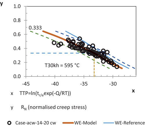
Figure 2. Wilshire data plots of the CW+a data presented in . The creep stresses are normalized by the Sandvik 24%CW tensile strength at temperature.
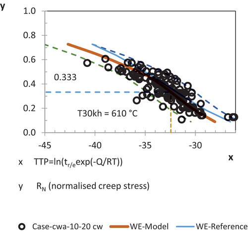
Figure 3. Wilshire data plots of the CW data presented in . The creep stresses are normalized by the Sandvik 24%CW tensile strength at temperature.
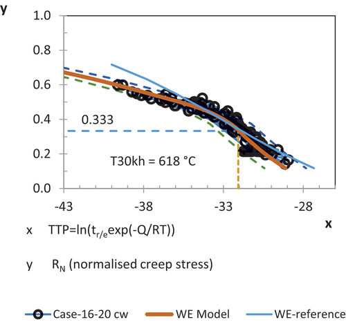
Table 3. Comparison of calculated TF, SF and T30kh against the reference creep model regardless of the level of cold work, specific to indicated material states in the sub-set. Note that the solution annealed heats, 210 min at 1150°C, were shown to be very detrimental in creep. The detrimental heat treatment was present mainly in the a+cw data sets.
The tests (with cold work) that also included information of 0.2% ‘nominal’ creep strain rate values were also assessed. For this study only tests that also had failure times reported were included in the assessment to be able to establish time factors between failure and 0.2% creep strain. The results of these assessments are given in .
Table 4. Comparison of calculated TF, SF and T30kh for virgin material time to 0.2% creep strain in relation to the reference creep failure model, regardless of the level of cold work and specific to the tabulated material states.
From these model results it is important to remember that the data sets include different cold work levels as was given in and do therefore only give a ‘generalized’ behaviour of the material state.
Now, to further determine the effect of cold work a multilinear correction of the Larson-Miller time-temperature parameter for the level of cold-work was solved. The multi-linear model finally chosen for the correction has the form given in Eq. 6. The regression statistics () show that a satisfactory multiple R2 can be achieved and that the statistical p values indicate that the CW parameter (and an additional temperature correction) are highly statistically significant. The choice of using the Larson-Miller model as base (instead of the WE model) was done due to better performance in regression statistics.
Table 5. Multilinear regression statistical output for estimating the larson-miller time to creep failure parameter of cold worked material and the impact (prolonging ↑/decreasing ↓ creep life) of the relevant input variables.
With the acquired correction model it is now possible to generate corrected time to failure estimates for any cold work level. As an example the generated ‘general’ model applied on the 16–20% CW data showed very promising results as can be seen in .
Table 6. Comparison of estimated T30 kh and scatter factors Z for best fit model for the limited data (only 16–20%CW represented) and the CW corrected model based on the full data.
Modelling results on irradiated material batches
The assessment on irradiated material was performed on a sub-data set of the original data base [Citation2]. The data set was put together by removing all tests with error codes. It was also culled to only include data points that were below the ‘rule of thumb’ creep strength of 80% of the specific virgin material batch strength. This was done to only include tests with ‘significant’ irradiation damage. This procedure naturally will make the outcome of the models conservative in nature. Also, to avoid very large scatter in the very short test duration end tests with failures below 10 hours were omitted. The results of the assessments are shown in .
Table 7. Comparison of calculated TF, SF and T30kh for irradiated material (all levels of DPA and cold work) against the reference material model. It is to be noted that the irradiation model correlation was performed on the cw+a irradiation data with the largest range of DPA and then applied on the other data sets.
As for the virgin material data sets the impact of cold work and the detrimental effect of the irradiation damage was approached through multilinear regression as described below.
Multi-linear regression model for irradiated material behaviour
The multilinear model for taking cold work and irradiation into account was attained from the cw+a data subset that consisted of 114 tests, having the largest range of DPA. The relatively small sets of 15 a+cw tests and 17 cw tests that are also studied here were both in-pile (MOL2) tests and could therefore behave differently than the post-irradiation creep data. This difference has been studied in [Citation5] on small data sets. It is to be noted that the in-pile data also ‘only’ has a maximum irradiation damage of 2.3 DPA, an order of magnitude less than the cw+a data set.
The data base report [Citation2] indicates that the uncertainty of the levels of DPA reported have an uncertainty of approximately 10%. The maximum failure time of the assessed irradiation exposed data is 8730 h, just a bit short for an estimation of the 30kh strength when applying the ECCC recommended rule of extrapolation of max. 3 times the longest test duration [39].
The multilinear correction for CW, DPA and irradiation temperature as given in Eq. 7 is resembling the one used for un-irradiated material. Also in this case, as shown in , the multiple R2 is quite satisfactory and the variable statistical p values indicate that both the CW level and the PDPA (DPA-temperature-parameter) and two additional temperature variables are statistically significant. The predicted versus measured PLM plot is shown in .
Figure 4. Predicted versus measured time-temperature parameter (PLM, normalized) for the multilinear model (Eq.7).
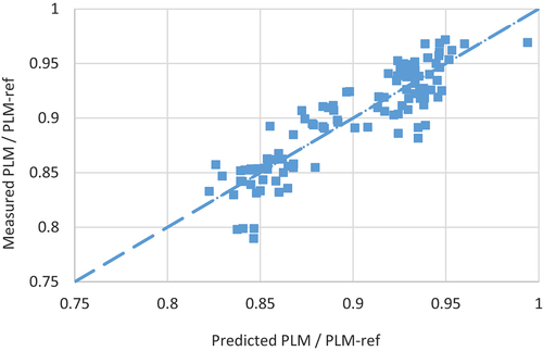
Table 8. Multilinear regression statistical output for estimating the Larson-Miller time to creep failure parameter of irradiated material and the impact (prolonging ↑/decreasing ↓ creep life) of the relevant input variables.
The multilinear correction for the PLM parameter lead to a significant improvement in the scatter factor from Z = 19.6 (note PLM based) to Zcorr = 10.7 for the cw+a data (see for WE based scatter factor), reaching a similar Z factor as was acquired for the virgin material assessment. This implies that the model indeed works satisfactorily.
With the acquired correction model it is now possible to generate corrected time to failure estimates for any cold work and irradiation level. As an example the generated ‘general’ model is applied to estimate the behaviour of 16% CW irradiated data in the range 0.05–1, 1–3, 3–10 and 10–30 DPA. The estimates are presented in . Note that the PDPA cannot be set to zero due to the logarithmic parameter description used.
Table 9. Reduction of T30 kh, as a function of DPA, i.e. ΔT30kh = T30kh(DPA1)- T30kh(DPA2). The ΔT30 kh can be added over the ranges, e.g. The reduction of temperature for 30kh of life between a ‘virgin’ state and 30 DPA is 30 + 10 + 11 + 10 = 61°C.
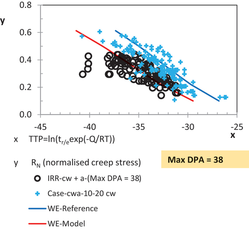
An additional fitting parameter describing a numerical variable representative of the material state, e.g. a Hollomon-Jaffe heat treatment parameter, could potentially further improve the predictions. The Wilshire data plot of the cw+a irradiated data in comparison to the virgin material is shown in . The tools for prediction of creep life and failure limit temperatures as a function of cold work and irradiation DPA have now been attained.
Figure 5. Wilshire data plots of the CW+a irradiated data in comparison to the virgin material to visualize the data scatter, overlap and creep strength differences.
A similar assessment can also be done for the time to 0.2% creep strain of irradiated material. As presented earlier the decrease of ductility caused by irradiation is expected to narrow the difference between the failure and time to 0.2% creep strain as many of the failed samples showed rather low failure strains. The preliminary assessment results for the cw+a are shown in in relation to the irradiated failure assessment.
Table 10. Comparison of calculated TF, SF and T30kh for irradiated material time to 0.2% creep strain against the time to failure of irradiated material (regardless of the level of cold work) note: the TF and SF values are here calculated against the irradiated material failure model. The irradiated failure temperature (30kh) for comparison is 558°C.
As can be seen the difference between irradiated failure and irradiated time to 0.2% creep strain seem to be negligible, especially when taking the scatter into account. Thus, if negligible thermal creep conditions are to be estimated the time to 0.2% strain cannot be used as base for defining the limits without applying additional safety factors in time or stress. The models defined in this work can thus be further used to support specific design conditions and in estimation of temperature limits.
Another reflection can be provided on the impact of pre-irradiation on the creep life according to the assessment provided in . As one can see, increasing DPA level reduces creep lifetime, while raising the irradiation temperature enhances it. Given the range of the irradiation temperatures assessed here, the main origin of the modification of the creep damage after the irradiation should come from the voids and possibly secondary phase formation/precipitate dissolution. One may speculate that prolonged irradiation indeed would contribute to the dissolution of TiC precipitates (coupled with RIS) as was observed in [Citation27]. On the other hand, high irradiation temperature (above ≥700 °C) does no longer cause intensive swelling and/or secondary irradiation induced phase formation, the generated irradiation defects are incorporated into the dislocation network. This could explain the lack of the creep life reduction with increasing irradiation temperature. Note that the above discussed trends are not linked with the in-pile irradiation creep, but are relevant for the creep measured in pre-irradiated samples.
Conclusion
The assessment of very challenging data sets have been studied in this paper. The impact of cold work on both the virgin material and the irradiated material can be estimated using an additional correction variables on the Larson-Miller parameter. For the irradiated material modelling additional variables, e.g. the PDPA and the irradiation temperature (if not the same as the creep test temperature) have to be applied to improve the creep life predictions and reduce the inherent scatter. The here applied multilinear models clearly reduce the scatter factors in the predictions.
The assessment outcomes of this work are summarised below.
Models for creep rupture life of ‘virgin’ 1515-Ti steel have been established for specific target material states using a large data set comprising of multi-heat, multi-material heats and multi test type (uniaxial and internal pressure) data.
Models for creep life of irradiated 1515-Ti cladding tubes with irradiation damage have been established for specific material states, cold work level and levels of irradiation damage.
The models can be applied for establishing failure temperature limits for specific design conditions of interest.
Establishing limits for ‘negligible creep’ for irradiated material cannot be performed for time to 0.2% creep strain due to low failure strains encountered for irradiated material without applying additional safety factors.
Abbreviations
| = | Ultimate tensile strength (MPa) at specified temperature T | |
| = | Yield/proof stress 0,2% (MPa) at specified temperature T | |
| = | Creep stress, engineering | |
| (MPa) | = | applied force divided by the original cross-section area or hoop stress for internally pressurized tubes |
| = | Mean rupture strength values (MPa) at specified time t and temperature T | |
| = | Mean Strength (MPa) for reaching 0,2% strain at specified time t and temperature T | |
| = | Normalized test stress, | |
| = | Time (h) | |
| = | Time to rupture (h) for a sample at specified T and initial stress | |
| = | Creep extension time to obtain 0,2% creep extension at specified T and | |
| = | Temperature of creep rupture, | |
| = | Temperature at which 30 000 h creep life is obtained (strain or life time) at 1/3 Rm(T) | |
| = | Larson-Miller Time-temperature parameter | |
| = | 0.2 percentage creep extension | |
| WE | = | Wilshire TTP parameter |
| k, u | = | Wilshire model parameters |
| Q | = | Wilshire activation energy for creep (J/mol) |
| R | = | The gas constant 8.314 J/mol/K |
| TF | = | Time Factor, tu-ref/tu-case |
| SF | = | Stress Factor, R0-case/R0-ref |
| Z | = | Time Scatter Factor, calculated scatter/confidence bounds |
Acknowledgments
This project has received funding from the Euratom research and training programme 2019-2020 under grant agreement No 945077.
Disclosure statement
No potential conflict of interest was reported by the author(s).
Additional information
Funding
References
- RCC-MRx. Design and construction rules for mechanical components of nuclear installations: high temperature, research and fusion, reactors, Afcen RCC-MRx code 2018. ed ed. Courbevoie, France: Afcen; 2018.
- Bergmann HJ, Zusammenstellung von Bestrahlungskriechdaten der Werkstoffe 1.4970 KV; 1.4970 KV, A und 1.4981 KV (Materialdatenreferenzliste). Interatom - Belgonucléaire, Report Nr.: ITB 403.31113_4, 1983.
- Bergmann HJ, Dietz W, Ehrlich K, et al., Entwicklung des Werkstoffs X10CrNiMiTiB 15 15 als Strukturmaterial für Brennelemente. Institution: FZK and Interatom/Siemens-KWU, Report Nr.: FZKA 6864, 2003.
- Cautaerts N, Delville R, Dietz W, et al. Thermal creep properties of Ti-stabilized DIN 1.4970 (15-15Ti) austenitic stainless steel pressurized cladding tubes. J Nucl Mater. 2017;493:154–167. doi:10.1016/j.jnucmat.2017.06.013
- Wassilew C, Schneider W, Ehrlich K. Creep and creep-rupture properties of type-1.4970 stainless-steel during and after irradiation, radiation effects and defects in solids 1986. Rad Eff. 1986;101(1–4):201–219. doi: 10.1080/00337578708224749
- Holmström S Determination of high temperature material properties of 15-15Ti steel by small specimen techniques, EUR 28746 EN. Luxembourg: Publications Office of the European Union; 2017. ISBN 978-92-79-72278-3. doi:10.2760/259065.
- Holmström SEA. Test methodologies for determining high temperature material properties of thin walled tubes, EUR 28642 EN. Luxembourg: Publications Office of the European Union; 2017. ISBN 978-92-79-69515-5. doi:10.2760/702821.
- CEN Technical Report, New approaches to determine negligible creep of steels for EN 13445, CEN/TC 54 WG59, Currently under review by CEN. Nov-2022.
- Holmström S. Defining a negligible creep temperature curve for Gr. 91 steel. Int J Pres Ves Pip. 2016;146:198–202. ISSN 0308-0161. doi: 10.1016/j.ijpvp.2016.07.004
- EN 13445-3:2014+A4 2018, Unfired pressure vessels - design
- Egnell L. An austenitic steel for high-temperature service applications. Metal Progress. 1970;98(3):102–107.
- Jung P, Sagués AA, Schroeder H, et al. Creep and creep rupture of thin stainless steel specimens. J Nucl Mater. 1978;74(2):348–350. 1994. doi: 10.1016/0022-3115(78)90373-2
- Latha S, Mathew MD, Parameswaran P, et al. Thermal creep properties of alloy D9 stainless steel and 316 stainless steel fuel clad tubes. Int J Pres Ves Pip. 2008;85(12):866–870. doi: 10.1016/j.ijpvp.2008.07.002
- Ehrlich K. Irradiation creep and interrelation with swelling in austenitic stainless steels. Journal of Nuclear Materials. 1981;100(1-3):149–166. doi:10.1016/0022-3115(81)90531-6
- Maillard A, Touron H, Seran JL, et al. (1994). Swelling and irradiation creep of neutron-irradiated 316ti and 15-15ti steels. Effects of Radiation on Materials: 16th International Symposium 1175, 20-25 Jun 1992, Denver, CO, United States, 824–837.
- Maziasz PJ, BUSBY JT. Properties of austenitic stainless steels for nuclear reactor applications. United States: Elsevier; 2012.
- Kesternich W, Meertens D. Microstructural Evolution of a Titanium-Stabilized 15Cr-15Ni Steel. Acta Metall. 1986;34(6):1071–1082. doi: 10.1016/0001-6160(86)90217-8
- Latha S, Mathew MD, Parameswaran P, et al. Effect of titanium on the creep deformation behaviour of 14Cr-15Ni-ti stainless steel. J Nucl Mater. 2011;409(3):214–220. doi: 10.1016/j.jnucmat.2010.12.240
- Mateus Freire L. Evolutions microstructurales et comportement en fluage à haute température d’un acier inoxydable austénitique, Ecole doctorale n°432. Microstructural evolutions and creep behaviour at high temperature of an austenitic stainless steel. PSL Research University; 2018.
- Nandedkar RV, Kesternich W. Effect of boron on high-temperature creep-behavior of austenitic stainless-steel DIN-1.4970. Metall Mater Trans A. 1990;21(12):3033–3038. doi: 10.1007/BF02647301
- Vijayanand VD, Parameswaran P, Nandagopal M, et al. Effect of prior cold work on creep properties of a titanium modified austenitic stainless steel. J Nucl Mater. 2013;438(1–3):51–57. doi: 10.1016/j.jnucmat.2013.03.014
- Cautaerts N, Delville R, Stergar E, et al. The role of Ti and TiC nanoprecipitates in radiation resistant austenitic steel: a nanoscale study. Acta Mater. 2020;197:184–197. doi: 10.1016/j.actamat.2020.07.022
- Cautaerts N, Delville R, Stergar E, et al. Tailoring the Ti-C nanoprecipitate population and microstructure of titanium stabilized austenitic steels. J Nucl Mater. 2018;507:177–187. doi: 10.1016/j.jnucmat.2018.04.041
- Cautaerts N, Delville R, Stergar E, et al. Characterization of (Ti,mo,cr)c nanoprecipitates in an austenitic stainless steel on the atomic scale. Acta Mater. 2019;164:90–98. doi: 10.1016/j.actamat.2018.10.018
- Bruemmer S, Simonen EP, Scott PM, et al. Radiation-induced material changes and susceptibility to intergranular failure of light-water-reactor core internals. J Nucl Mater. 1999;274(3):299–314. doi: 10.1016/S0022-3115(99)00075-6
- Kenik EA, Hojou K. Radiation-induced segregation in FFTF irradiated austenitic stainless steels. J Nucl Mater. 1992;191-194:1331–1335. doi: 10.1016/0022-3115(92)90691-D
- Maziasz P. J. Formation and stability of radiation-induced phases in neutron-irradiated austenitic and ferritic steels. J Nucl Mater. 1989;169(C):95–115. doi: 10.1016/0022-3115(89)90525-4
- Lee E, Maziasz P, Rowcliffe A, The structure and composition of phases occurring in austenitic stainless steels in thermal and irradiation environments. Tech. rep. Oak Ridge National Lab, 1980. URL: https://tinyurl.com/y4ukccah
- Zinkle S, Maziasz P, Stoller R. Dose dependence of the microstructural evolution in neutron-irradiated austenitic stainless steel. J Nucl Mater. 1993;206(2–3):266–286. doi: 10.1016/0022-3115(93)90128-L
- Garner FA. Comparison of swelling and irradiation creep behavior of fcc-austenitic and bcc-ferritic/martensitic alloys at high neutron exposure. ISSN 0022-3115. J Nucl Mater. 2000;276(1–3):123–142. doi: 10.1016/S0022-3115(99)00225-1
- Wilshire B, Scharning PJ, Hurst R. A new approach to creep data assessment. Mater Sci Eng A. 2009;510–511:3–6. ISSN 0921-5093. doi: 10.1016/j.msea.2008.04.125
- Rantala J, Moilanen P, Ehrnsten U, et al., Results of creep tests of pressurized cladding tubes, materials testing and rules (MATTER), Deliverable D3.7, 2015.
- ECCC Recommendations Volumes 5 Part 1a. Generic recommendations and guidance for the assessment of full size creep rupture datasets, issue 6. Holdsworth, S.R., ed. Italy: publ. Centro Sviluppo Materiali; 2014.
- Mateus Freire L, Evolution microstructurales et comportement en fluage a haute temperature d’un acier inoxydable austenitique. PhD Thesis, Ecole doctorale n°432, 2018
- Final report summary - MATTER (MATerials TEsting and Rules), CORDIS data base on EU-Funded projects, https://cordis.europa.eu/project/id/269706/reporting/fr