
 ?Mathematical formulae have been encoded as MathML and are displayed in this HTML version using MathJax in order to improve their display. Uncheck the box to turn MathJax off. This feature requires Javascript. Click on a formula to zoom.
Abstract
The Brenner Base Tunnel (BBT), a 64 km long railway tunnel between Austria and Italy, is under construction at the time of writing. The complete tunnel system of the BBT will comprise railway tunnels as well as exploration, emergency, ventilation and access tunnels. The latter are tunnels with generally lower requirements on the serviceability, watertightness, durability, surface quality or availability. In some cases, a single permanent shotcrete lining can fulfill the reduced requirements and offers a very economic tunnel design. Realistic assessment of the load-bearing capacity of shotcrete linings is particularly required for early and large deformations in deep tunnels. This is the motivation for a more sophisticated approach to the back-analysis of a permanent shotcrete lining of a single lined rescue tunnel of the BBT. Thus, a detailed finite element model is developed for analyzing the bearing capacity of the permanent shotcrete lining on the basis of an advanced constitutive model considering the time-dependent and nonlinear material behavior of shotcrete. The material model represents the time-dependent evolution of material properties due to hydration of shotcrete, hardening and softening material behavior, the latter resulting in cracking or crushing of shotcrete, creep and shrinkage. In the finite element model, the time-dependent construction process of the drill-and-blast method for tunnels driven by partial face excavation is considered. The material parameters for the shotcrete model were calibrated based on an experimental program, performed with specimens sampled directly on the construction site of the BBT.
Introduction
The Brenner Base Tunnel (BBT) is a priority European infrastructure project on the Scandinavian–Mediterranean Corridor from Helsinki (Finland) to La Valletta (Malta). The corridor connects the economic centers and ports in Italy with those in Germany and Scandinavia and will be used especially for freight traffic. One main part of this corridor is the BBT. The two 64 km long, parallel, single-lane railway tunnels of the BBT enable a flat railway crossing of the Alps between Austria and Italy.Citation1 In the future, freight and passenger trains will cross the Alps more ecologically on this route, with higher loading capacities and shorter connection times, without having to cross the Brenner Pass at an altitude of 1371 m. The total tunnel system of the BBT will comprise a total length of 230 km. Half of the tunnel length comprises railway tunnels, the other half being exploration, emergency, ventilation and access tunnels. The latter are tunnels with, in general, fewer requirements on the serviceability, such as watertightness, surface quality and availability. In some cases, a single permanent shotcrete lining is fulfilling these requirements, and offers a very economic tunnel design. To ensure the structural safety of permanent shotcrete linings of deep tunnels, special attention should be paid to determining reliably the rock loads.
Design of Shotcrete Linings at the BBT
For shotcrete linings, two concepts are distinguished at the BBT:Citation2
Temporary shotcrete linings: These are built for a service life of at least 10 years for the construction phase and are designed on the basis of the semi-probabilistic approach, characterized by partial safety factors for the external actions and resistances, for a service life of 50 years.
Single shell permanent shotcrete linings: These consist of one monolithic shotcrete lining, and are designed based on an increased reliability index. The requirements, acting loads and load-bearing capacities of the linings must be evaluated precisely. For this purpose, the shotcrete lining thickness, shotcrete properties and deformations of the lining are monitored to evaluate the loading and resistance and to ensure the structural safety and serviceability.
In addition, securing measures such as rock bolts are employed, with a service life of 10 years.
Today, for the design of a shotcrete lining, the temporal development of convergences, of the shotcrete properties and of the relaxation of the shotcrete stress are taken into account only in a crude approximation. Usually, a softer, linear-elastic material behavior with a hypothetical modulus of elasticity of 30–50% of the nominal stiffness according to Ref. [Citation3] is considered for capturing those effects. This hypothetical modulus of elasticity replaces consideration of the development of stiffness of the shotcrete and creep effects. This widely used simple approach allows for a rough estimate of the load-bearing capacity of usual tunnel advances, but slow and long-lasting convergences or fast-curing shotcrete types are generally not covered by this approach.Citation4 For this reason, it is insufficient for the simulation of shotcrete linings under early high loads in deep tunnels or for determining the limit state of deep single-shell permanent shotcrete linings by back-analyses.
Hence, in the present contribution, for such back-analyses a sophisticated numerical model of tunnel advance is developed and calibrated such that the model results fit the displacements measured at the tunnel site. Supported by advanced material models, a calibrated model of deep tunneling then allows assessment of the stresses arising in the tunnel support structure, e.g. the shotcrete lining.
For deep tunnels, temporary shotcrete linings may be heavily loaded from the beginning, resulting in large strains and high stresses in the lining, with a potential for crack development. The solidification of the shotcrete and the development of the shotcrete properties (e.g. Young's modulus, compressive and tensile strength, ductility, shrinkage and creep behavior) are of importance for these linings. Of particular importance are the creep effects of very early loaded shotcrete. In addition, stress redistributions from nearby tunnel advances on existing shotcrete linings have to be taken into account, as highly loaded shotcrete linings of deep tunnels often withstand only minor deformations imposed later on before the onset of damage.
The design of a single permanent shotcrete lining requires a detailed analysis of the load-bearing capacity of the loaded tunnel structure. Considering the time dependence of the material behavior and the construction process leads to a realistic assessment of the load-bearing capacity.Citation4
Aim of the Paper
In the present paper, the back-analysis of a single permanent shotcrete lining of an emergency tunnel at the BBT is presented, using the time-dependent nonlinear material model for shotcreteCitation5 within a finite element model considering the actual tunnel construction process.
The presented back-analysis aims at an accurate prediction of the stress state arising in the shotcrete lining during the construction process by means of an advanced yet computationally efficient numerical model based on nonlinear constitutive laws for rock mass, shotcrete and additional securing measures. While the main focus is on the analysis of the shotcrete lining during and immediately after the construction process, the presented numerical model can also be used for evaluating the long-term structural response of the tunnel.
It will be shown that such a back-analysis, calibrated by geodetic measurements and accounting for the construction process, facilitates important insights into the degree of utilization of permanent shotcrete linings, even for complex cross-sectional geometries and tunnels driven by partial excavation.
The remainder of the paper is organized as follows. Subsequent to the description of the considered tunnel section, the finite element model is presented together with the time-dependent nonlinear material model for shotcrete. The required material parameters for the new shotcrete model are identified by an experimental program, which is described in brief. Then, the numerical results are presented and discussed. The paper concludes with a summary and prospects for future research efforts.
Permanent Shotcrete Lining of an Emergency Tunnel at the BBT
Parallel to the bypass tunnel of Innsbruck, which was built in 1994, an emergency tunnel was built as part of the BBT project to upgrade the bypass tunnel to current safety standards. The emergency tunnel, characterized by a 47 m2 excavation profile ( ) and a length of 9.1 km, is connected every 333 m by cross passages to the bypass tunnel. The tunnels are located at a distance of 30 m from each other. In most sections the cross-section was built without an invert. The investigated section is characterized by an approximate overburden of 320 m.
Fig. 1: Longitudinal view and cross-section of the investigated tunnel section, together with the dimensions, tunnel support structure and partial excavation scheme
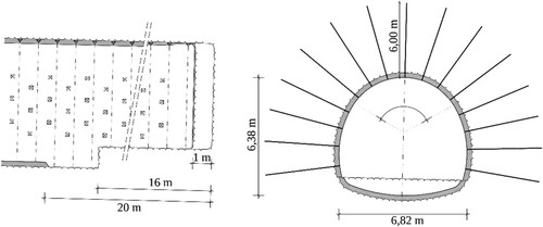
The requirements for emergency tunnels are less demanding compared to those for railway tunnels. Hence, a single-shell permanent shotcrete lining meets the serviceability requirements according to Ref. [Citation6]. The durability requirements are met using an increased concrete cover of 55 mm, monitoring class 3 (ÜK3) and a maximum crack opening of 0.3 mm in the homogeneous geological sections. The planning design assumed a single-shell permanent shotcrete lining with a thickness of 250 mm and two layers of reinforcement to fulfill the structural safety requirements. For fault zones and sections of higher convergences, the space for a secondary lining is kept within the standard cross-section. To determine the load-bearing capacity by back-analysis, the convergence monitoring was carried out with five monitoring points per cross-section, taking an initial measurement as soon as possible after construction of the first shotcrete layer. In addition, three-dimensional laser scanning at two construction stages was carried out to check the excavation profile and the shotcrete profile. The built lining thickness was measured at this section with an average thickness of about 450 mm at the crown to 500 mm at the sidewalls.Citation7 The structural behavior of a lining with irregular distributions of the thickness is strongly influenced by the regions of lower thickness and stiffness. Hence, for the simulation a uniform thickness of 400 mm is assumed for both the crown and sidewalls.
Geology
The emergency tunnel is driven in Innsbruck quartz phyllite with intercalations of limestone, dolomitic marble and green schists. The eastern section (up to Tunnel Meter 4600) is located in the Silurian carbonate–sericite phyllite series and the western section in the Ordovician quartz phyllite–green schist series. The series are separated by the steeply incident Hasental fault. Brittle tectonic faults are common and the main fault system is the almost axis-parallel Lavierental fault system. At the Tulfes portal there are quaternary loose sediments and further granular soil sections, for a total of 200 m, of ground moraine, which were cut through during the tunnel excavation. In the predominant phyllite zones, the schists breaks up easily into thin layers which consist of layered silicates and quartz. However, it is a dense rock due to its high proportion of mica, which results in low water conductivity and low water inflows to the tunnel. The geology is illustrated in .
Fig. 2: Illustration of the geology in the investigated section
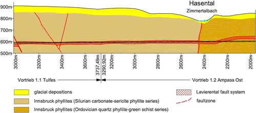
During the construction of the bypass tunnel (1989–1993), 30 m from the emergency tunnel, a total water flow of 10 L/s was documented. In the past 4 years, an average rate of 5.1 L/s (minimum 3.0 L/s to maximum 10.2 L/s) was measured in the bypass tunnel. For the construction of the emergency tunnel running parallel to it over the complete length, it was assumed that the total amount of water due to the drainage of the existing bypass tunnel would be small and no major water ingress was to be expected. In case of dripping water ingress, the water is drawn off before shotcreting. In this area, the chemical analyses of the water samples show very low sulfate ion concentrations (e.g. sulfate 41.0 mg/L). Due to the existing calcite saturation in the mountain water, deterioration of the concrete can be excluded.
Finite Element Simulation of Tunnel Advance
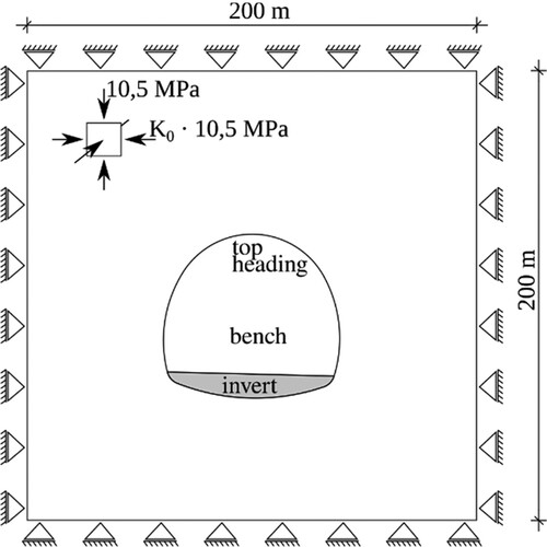
The back-analysis of the permanent shotcrete lining of the emergency tunnel is performed by means of a two-dimensional (2D) finite element model using the finite element software ABAQUS.Citation8 A domain of 200 m × 200 m is considered in the model, assuming plane strain conditions (
). Regarding boundary and initial conditions, displacements perpendicular to the model boundary are prescribed, and an initial geostatic stress state, characterized by the vertical compressive stress component of 10.5 MPa and a lateral stress coefficient of = 0.55, is assumed. In the present analysis, the bypass tunnel near the emergency tunnel is neglected.
Fig. 3: 2D plane strain model of the emergency tunnel, with the boundary and initial conditions and the excavation profile: top heading and bench (excavated simultaneously) and invert
For the surrounding rock mass, a linear-elastic perfectly plastic material model, based on the Mohr–Coulomb yield criterion and a non-associated flow rule, is used, with a Young's modulus of 500 MPa, Poisson's ratio of 0.12, cohesion stress of 0.4 MPa, friction angle of 25° and dilation angle of 0°. A higher Young's modulus of 1500 MPa and a higher cohesion stress of 1 MPa are assumed in the region beneath the tunnel.
To represent the material behavior of shotcrete, the time-dependent damage plasticity modelCitation5 is employed. The model, the calibration procedure based on a comprehensive experimental program and the employed material parameters are described in the next section.
In addition to the shotcrete lining, 15 rock bolts with a cross-sectional area of 654.5 mm2 and a length of 6 m each ( ) are modeled with truss elements. For the rock bolts, linear-elastic perfectly plastic material behavior is assumed, characterized by a Young's modulus of 210 000 MPa and a yield stress of 550 MPa.
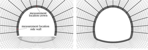
Because of the time-dependent material behavior of shotcrete, the construction process, consisting of a partial excavation sequence, must be represented properly in the simulation. At the construction site, the top heading and the bench were excavated simultaneously, whereas the invert was excavated approximately 108 h, i.e. 4.5 days, later. The shotcrete lining with an average thickness of 400 mm (top heading and bench) and 300 mm (invert) is discretized by fully integrated eight-node quadrilateral elements with eight elements across the thickness. The finite element mesh used is shown in . From the geometry, the initial conditions and the boundary conditions follow symmetry with respect to the vertical axis passing through the tunnel crown.
Fig. 4: Finite element mesh after excavation of the top heading and the bench (left) and after excavation of the invert and placement of the complete shotcrete lining (right)
To consider the sequential partial excavation procedure, the simulation is performed according to the commonly employed stress release method,Citation9,Citation10 by a sequence of three simulation steps:
Excavation of the top heading and the bench: the initial stress acting on the excavation boundary of the top heading and the bench, corresponding to the initial geostatic stress, is released according to the initial stress release ratio of 80%.
The part of the shotcrete lining for securing the excavation of the top heading and the bench and the rock bolts are installed in a stress-free state, and the remaining 20% of the geostatic stress is released according to the stress release layout.
108 h after excavation of the top heading and the bench, the invert is excavated and the lower part of the shotcrete lining is placed simultaneously.
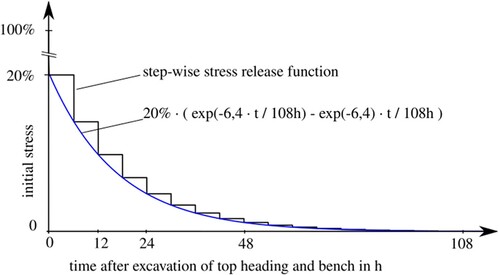
For simulation step 2, the employed step-by-step stress release layout for excavation of the top heading and the bench follows an exponential decline, assuming 18 excavation steps in the longitudinal direction and assuming that the geostatic stress will be completely released after 108 h. Accordingly, idle periods of 6 h between two subsequent excavation steps are considered for operations between the excavation steps. The stress release layout is illustrated in .
In contrast to simulation step 2, in simulation step 3 the excavation of the invert, 108 h after excavation of the top heading and the bench, is performed by a single excavation step within 2 h, and no stress release prior to placement of the lower part of the lining is considered.
To assess the influence of the time-dependent material behavior of shotcrete on the structural response, the temporal evolution of displacements and stresses is evaluated at two characteristic locations of the shotcrete lining, i.e. at the crown and at the side wall. Both locations are indicated in .
The finite element model is calibrated to measurement data as follows. The initial geostatic stress state and the material parameters for the surrounding rock mass are chosen within the proposed bandwidth according to the geological survey, aiming at a good fit with the geodetically measured long-term displacements at the crown and the side wall of the tunnel. In addition, the time-dependent stress release function ( ) is fitted by the time-dependent evolution of the displacements measured at the crown and the side wall.
Fig. 5: Assumed time-dependent stress release layout after excavation of the top heading and the bench in the 2D finite element model
Time-Dependent Nonlinear Material Model for Shotcrete
The shotcrete damage plasticity (SCDP) model representing the nonlinear, time-dependent material behavior of shotcrete was presented in Ref. [Citation5] and extended in Ref. [Citation11]. It was derived from three advanced material models for normal concrete, i.e. the model for concreteCitation12 to represent inelastic material behavior and stiffness degradation due to damage based on a damage plasticity framework, the approach according to the American Concrete Institute (ACI) committee 209 recommendationCitation13 to model shrinkage of shotcrete based on an empirical time function which attains an asymptotic ultimate shrinkage strain in infinite time, and the viscoelastic solidification theoryCitation14 to represent hydration-dependent stiffness and nonlinear creep. In addition, to describe the evolution of material strength and ductility due to hydration, empirical time functions are employed. The stress–strain relation in the total form is expressed as
where
denotes the nominal stress (force per total area),
is the isotropic scalar damage parameter for modeling degradation of stiffness and reduction of material strength, and
is the constant fourth order instantaneous elastic stiffness tensor. The total strain
is decomposed into the instantaneous elastic strain
, the plastic strain
, the viscoelastic short-term creep strain
, the viscous long-term creep strain
and the shrinkage strain
.
The model is characterized by a single yield surface for delimiting the viscoelastic domain. The evolution of the damage parameter is directly linked to the accumulation of the plastic strain
once the material strength is attained, and it evolves depending on the magnitude of the confining stress. Accordingly, ductile material behavior in multiaxial compression and brittle behavior in tension can be represented properly. The rate laws describing the evolution of the individual strain components
and
and the damage parameter
are described in detail in Refs. [Citation5] and [Citation11]. Hence, they are omitted here for the sake of brevity.
For the subsequently presented finite element simulations, the material model was implemented as a user subroutine in ABAQUS exploiting the UMAT interface. In principle, implementations in other finite element codes providing such user-defined material interfaces (e.g. PLAXISCitation15) are possible and have been tested successfully. A comparison of the SCDP model with other shotcrete models available in the literature, e.g. the model in Ref. [Citation16], which is also available in PLAXIS, can be found in Ref. [Citation9]. Therein, the models were compared and assessed based on a finite element model of deep tunnel advance.
Calibration of the Shotcrete Model
Since only a few and rather old experimental series on shotcrete are available in the literature, most of them determined for outdated dry-mix shotcrete compositions, an experimental program was designed to determine the material parameters of the shotcrete model. For this purpose, the required shotcrete specimens were sampled at the BBT during tunnel construction.Citation17
The time-dependent hydration process of shotcrete is influenced by many parameters, for instance the quantity and type of cement and its grinding fineness, the chemical accelerator used, the ambient temperature and the type of aggregates. The choice of binders and additives enables the setting behavior to be adjusted locally, depending on necessary requirements.
Basically, two requirements for shotcrete in deep tunnels are identified:
a safe overhead application of shotcrete under all project conditions, which is achieved by means of a strongly accelerated start of solidification
a damage-free lining for regular conditions.
Considering the early strength classes J1, J2 and J3 of the Guideline for Shotcrete of the Austrian Concrete Society,Citation18 the shotcrete on site was a wet mix SpC25/30/(56)/ÜK3/J2/XC4/XF3/GK8. The contractor applied the shotcrete recipe according to and clearly complied with the requirements.
Table 1: Shotcrete composition used for the permanent shotcrete lining in the emergency tunnel
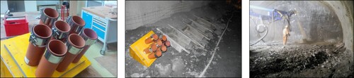
For the laboratory tests, cylindrical specimens were used, which were sampled using two different techniques: for tests on shotcrete younger than 24 h, a novel technique was employed, using specimens directly sprayed into tubular molds, whereas for tests on shotcrete older than 24 h, both sprayed specimens and standard drill cores, sampled from spray boxes, were used. Sprayed specimens could be unmolded 6 h after casting, and laboratory tests were started immediately afterwards. For the sprayed specimens, special care was taken in terms of the spraying direction, which must be aligned with the axis of the tubular molds to minimize the number of faulty specimens due to shotcrete rebound and air pockets. The tubular molds and spray boxes used for drill cores, as well as the production of sprayed specimens at the tunnel face, are depicted in .
Fig. 6: Molds for spraying directly cylindrical specimens (left), molds and spray boxes placed at the tunnel site (center), and spraying of cylindrical specimens at the tunnel face (right)
The experimental program comprised the determination of the evolution of Young's modulus, from the material age of 24 h to 28 days, and of the uniaxial compressive strength from 6 h to 28 days, as well as shrinkage and creep tests on specimens, with the last two tested on sealed specimens to exclude drying effects.
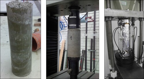
Shrinkage and creep tests were started simultaneously for three different maturities of shotcrete, i.e. at 8, 24 and 27 h, and lasted for 56 days each. During the shrinkage and creep tests, the time-dependent strain was determined at the center of the specimens by measuring the time-dependent length changes related to a measuring length of 200 mm, using three displacement transducers which were arranged at equal distances along the perimeter of each specimen. Creep tests were conducted using a hydraulic creep test bench, and the magnitude of the applied compressive load was chosen to ensure linear viscoelastic material behavior. The creep specimens were loaded at shotcrete ages of 8, 24 and 27 h with compressive stresses of 1.9, 2.9 and 2.7 MPa, respectively, and the applied load was held constant throughout the complete testing period. shows an unmolded sprayed cylindrical specimen 6 h after casting, an unsealed specimen during a laboratory test for determining the uniaxial compressive strength, and a sealed specimen during a creep test in the hydraulic test bench.
Fig. 7: Sprayed shotcrete specimen, unmolded 6 h after spraying (left), unsealed specimen for determining the uniaxial compressive strength (center), and sealed specimen mounted in a hydraulic creep test bench (right)
Based on the experimental results, the material parameters of the SCDP model were calibrated, as reported in detail in Ref. [Citation17], and the identified parameters are summarized in . To represent softening material behavior properly in finite element simulations, the model is regularized by means of the specific mode I fracture energy, determined at the age of 28 days, and the characteristic length of a finite element. The specific mode I fracture energy was determined by means of wedge splitting tests, as reported in Ref. [Citation19].
Table 2: Calibrated material parameters for the shotcrete damage plasticity (SCDP) model
The experimental results on the evolution of the Young's modulus and the uniaxial compressive strength, determined in 2017,Citation17 and the additional data, determined in 2018,Citation19 are shown together with the respective predictions by the calibrated SCDP model in .
Fig. 8: Predicted evolution of the uniaxial compressive strength (left) and the Young's modulus (right): experimentally determined values from Ref. [Citation17] and additional experimental data from 2018,Citation19 and predictions by the calibrated shotcrete damage plasticity (SCDP) model
![Fig. 8: Predicted evolution of the uniaxial compressive strength (left) and the Young's modulus (right): experimentally determined values from Ref. [Citation17] and additional experimental data from 2018,Citation19 and predictions by the calibrated shotcrete damage plasticity (SCDP) model](/cms/asset/65c7449e-13ca-4699-abc2-6747f48af15f/tsei_a_1735979_f0008_c.jpg)
Results
Deformations of the Shotcrete Lining
First, the predicted vertical displacement of the crown and the horizontal displacement of the tunnel side wall are compared with the available geodetic measurement data. To this end, the computed horizontal displacement of the side wall is compared with the mean value of the respective displacements of both side walls, and the computed vertical displacement at the crown is compared with the geodetically measured displacement at the crown. In addition, the mean value and standard deviation of the measured side wall displacements and of the measured vertical displacement at the crown are computed for a tunnel length of 100 m, comprising 13 geodetic measurement cross-sections in total.
shows the predicted evolution of the vertical displacement of the shotcrete lining determined at the crown and the horizontal displacement at the side wall, both after placement of the shotcrete lining, as well as the mean values and standard deviation of the geodetic values. Furthermore, it can be seen in that the largest displacement increments are accumulated during the first excavation steps within a period of 54 h. The displacements increase slightly during the idle periods between the excavation steps due to creep and shrinkage.
Fig. 9: Predicted evolution of the vertical displacement at the crown and horizontal displacement at the side wall, and statistical bandwidth according to geodetic measurements
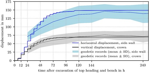
Subsequent to the excavation of the invert, i.e. 108 h after placement of the upper part of the shotcrete lining, the lining is completed by placing the lower part. However, it can be seen in that the excavation of the invert has virtually no influence on the displacement at the crown, while a minor increase in the side wall displacement is predicted.
Comparison of the computed results with the geodetic measurements shows satisfactory agreement of the results, computed by the calibrated model, with the observed behavior. In particular, the long-term behavior at the crown is predicted very well by the model, while the side-wall displacements are overestimated slightly between 48 and 72 h after excavation of the top heading and the bench.
Stress State in the Shotcrete Lining
For the shotcrete lining, the three principal stress directions coincide approximately with the circumferential, longitudinal and radial directions. Based on the 2D plane strain model, the circumferential stress and radial stress are obtained as in-plane components, whereas the longitudinal stress is given as the out-of-plane component. Since the radial stress is negligibly low compared to the circumferential stress and the longitudinal stress, the stress state in the shotcrete lining is classified as biaxial.
shows the temporal evolution of the circumferential stress acting in the lining predicted at the rock–shotcrete interface and the free surface at the crown and the side wall. A high compressive stress compared to the evolving shotcrete strength in uniaxial compression is predicted at the free surface at the crown, with the maximum value attained after the ninth excavation step, i.e. 54 h after placement of the upper part of the lining. This stress state at the crown is a result of the large vertical displacements at the crown in combination with a late placement of the lower part of the shotcrete lining.
Fig. 10: Predicted evolution of the circumferential stress at the rock–shotcrete interface and the free surface at the crown and the side wall
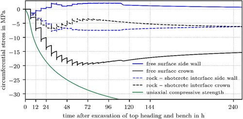
In contrast, a negligibly low compressive stress is predicted at the free surface at the side wall during the first excavation steps, which changes to a tensile stress after 18 h. The kinks at 108 h indicate the excavation of the invert.
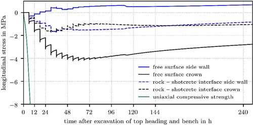
depicts the corresponding longitudinal stress predicted at the crown and the side wall. At the crown, again a higher compressive stress is present at the free surface compared to the rock–shotcrete interface. In contrast, at the side wall a low compressive stress is predicted at the free surface compared to the rock–shotcrete interface, which again changes to tension after 24 h. Beginning from 24 h after placement of the shotcrete lining, at the rock–shotcrete interface at the side wall the compressive longitudinal stress is decreasing, whereas the tensile stress at the free surface at the side wall is slightly increasing due to stress redistribution within the lining. This stress redistribution demonstrates the influence of creep and shrinkage on the structural response of the shotcrete lining.
Fig. 11: Predicted evolution of the longitudinal stress at the rock–shotcrete interface and the free surface at the crown and the side wall
The distributions of the circumferential and longitudinal stress along the shotcrete lining are illustrated in for material ages of 54 and 108 h, respectively. Here, the kinks in the stress distributions indicate the influence of the rock bolts on the stress state in the shotcrete lining. It can be seen that the circumferential compressive stress at the free surface attains a magnitude of approximately 27 MPa with a local maximum of 29 MPa at a rock bolt, while the respective longitudinal compressive stress does not exceed 7 MPa. A comparison of the circumferential stress with the uniaxial compressive strength of 26 MPa at the shotcrete age of 54 h reveals that the uniaxial compressive strength is exceeded slightly at this location. However, given the fact that the material can sustain higher stresses under compressive biaxial stress states, the arising stress state must be rated in terms of the biaxial strength envelope of shotcrete: for the prevailing ratio of circumferential compressive stress to longitudinal compressive stress of approximately 4:1, shotcrete can sustain the higher compressive circumferential stress of 33 MPa compared to the uniaxial compressive strength of 26 MPa. Hence, the biaxial material strength is not attained, but the shotcrete lining is just loaded to a considerable extent. The comparison is slightly conservative since the imposed deformations of the shotcrete lining in the finite element model slightly exceed the geodetically observed ones 54 h after placing the shotcrete lining ( ).
Fig. 12: Predicted circumferential stress (left) and longitudinal stress (right) along the shotcrete lining at the rock–shotcrete interface and the free surface for t = 54 h and t = 108 h
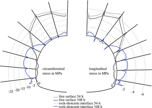
According to , , both the compressive circumferential and compressive longitudinal stresses decrease with time due to stress relaxation and shrinkage, while the uniaxial compressive strength increases due to ongoing hydration. Hence, the utilization of the shotcrete lining decreases as time progresses.
Subsequent to excavation of the invert, 108 h after excavation of the top heading and the bench, the lower part of the lining is placed in a stress-free state and the remaining stress acting on the excavation boundary is released within 2 h. shows the resulting contour plot of the circumferential stress and the longitudinal stress acting in the completed lining 132 h after placement of the upper part, i.e. 24 h after placement of the lower part.
Fig. 13: Contour plot of the circumferential stress (left) and the longitudinal stress
(right) acting in the shotcrete lining 132 h after excavation of the top heading and the bench, i.e. 24 h after placement of the lower part of the lining
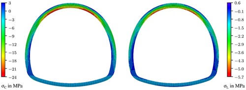
In the upper part of the shotcrete lining, a comparatively high compressive stress, up to 24 MPa in the circumferential direction and 5.7 MPa in the longitudinal direction, prevails at the free surface at the top heading. In contrast, minor tensile and compressive stresses in the circumferential and longitudinal directions are obtained at the side walls.
Compared to the upper part of the lining, in the lower part of the shotcrete lining a considerably lower circumferential compressive stress prevails. Furthermore, minor tensile stresses in the longitudinal direction act in some areas of the lower part as a consequence of shrinkage in combination with a low compressive stress due to excavation.
After 132 h, the stresses in the shotcrete lining have been reduced by creep, and accordingly the degree of utilization has already decreased. Hence, for the present case the maximum value of the utilization of the lining occurs during the construction process.
Conclusions
A back-analysis of the deformations and the stress state of a single, permanent shotcrete lining, installed in an emergency tunnel of the BBT, was presented. To this end, a 2D finite element model was developed, accounting for the individual steps of the construction process and the nonlinear, time-dependent material behavior of shotcrete. To describe the latter, the SCDP model was employed. Material phenomena such as hydration-dependent material properties, creep and shrinkage can be represented in the simulation by means of the SCDP model, and their influence on the structural response can be captured realistically. The material parameters were identified from a comprehensive experimental program conducted on shotcrete specimens sampled at the construction site.
The finite element model was calibrated based on geodetic measurements of the tunnel convergence, such that the deformations computed by the numerical model coincide with the measured ones. Accordingly, the stress state prevailing in the shotcrete lining was computed and the degree of utilization was assessed. Considering the predicted high degrees of utilization, the need for such an advanced shotcrete model was demonstrated.
Such back-analyses allow a detailed insight into the load-bearing capacity of a shotcrete lining. For early and highly loaded single permanent linings of deep tunnels in particular, these insights help to avoid overloading and damage of the linings. Moreover, based on those insights, similar projects could be designed more economically. The presented back-analysis method can be applied to other examples of tunnel advance, provided that the model can be calibrated by means of measurement data on deformations.
For the present analysis, local failure of rock mass was not considered. Capturing such phenomena requires more advanced material models. For back-analyses of tunnel sections for which such local failure zones are observed, a more advanced constitutive model should be used for the surrounding rock mass.
Although the present back-analysis concentrated on the construction process, the method can be also employed for investigating the long-term response. In particular, for such long-term investigations the influence of rock bolts or other securing measures can be investigated. However, for long-term studies the time-dependent and orthotropic material behavior of the surrounding rock mass should also be taken into account, which again requires more advanced material models.
A follow-up experimental program on young shotcrete is currently being performed, investigating the hydration-dependent evolution of temperature, porosity and mechanical properties, such as stiffness, uniaxial compressive and uniaxial tensile strength, and the specific mode I fracture energy. In addition, shrinkage and linear and nonlinear creep behavior are investigated under sealed and unsealed conditions. This follow-up experimental program will allow researchers to gain more insight into the complex nonlinear time-dependent material behavior of shotcrete.
Disclosure statement
No potential conflict of interest was reported by the authors.
References
- Bergmeister K. Brenner Basistunnel - Brenner Base Tunnel - Galleria di Base del Brennero, Tappeiner Verlag, 2011.
- Cordes T, Hofmann M, Murr R, Bergmeister K. Aktuelle Entwicklungen der Spritzbeton-technologie und Spritzbetonbauweise am Brenner Basistunnel. In 12. Spritzbeton-Tagung, Alpach, Tirol, 2018.
- Pöttler R. Time-dependent rock–shotcrete interaction a numerical shortcut. Comput. Geotech. 1990; 9: 149–169. doi: 10.1016/0266-352X(90)90011-J
- Cordes T, Schneider-Muntau B, Bergmeister K. Inverse analysis of the loading state of a single permanent shotcrete lining at the BBT. In ECCOMAS EURO:TUN, Innsbruck, 2017.
- Neuner M, Gamnitzer P, Hofstetter G. An extended damage plasticity model for shotcrete: formulation and comparison with other shotcrete models. Materials 2017; 10: 1.
- European Committee for Standardization. EN 1992-1-1: Design of Concrete Structures. CEN: Brussels, 2015.
- SKAVA consulting ZT-GmbH. Design of the permanent rescue tunnel - BBT H33. BBT Internal, Innsbruck, 2018.
- Abaqus. ABAQUS v6.14 Documentation. Simulia, Dassault Systèmes, Providence, Rhode Island, 2015.
- Neuner M, Schreter M, Unteregger D, Hofstetter G. Influence of the constitutive model for shotcrete on the predicted structural behavior of the shotcrete shell of a deep tunnel. Materials 2017; 10: 6.
- Schreter M, Neuner M, Unteregger D, Hofstetter G. On the importance of advanced constitutive models in finite element simulations of deep tunnel advance. Tunnelling and Underground Space Technology 2018; 80: 103–113. doi: 10.1016/j.tust.2018.06.008
- Neuner M, Schreter M, Hofstetter G. Comparative investigation of constitutive models for shotcrete based on numerical simulations of deep tunnel advance. In Numerical Methods in Geotechnical Engineering: 9th European Conference on Numerical Methods in Geotechnical Engineering, CRC Press Taylor & Francis Group, 2018, pp. 103–108.
- Grassl P, Jirásek M. Damage-plastic model for concrete failure. Int. J. Solids Struct. 2006; 43: 7166–7196. doi: 10.1016/j.ijsolstr.2006.06.032
- ACI Committee, 209. 209R-92: Prediction of Creep, Shrinkage, and Temperature Effects in Concrete Structures, 1992.
- Bažant ZP, Prasannan S. Solidification theory for concrete creep. I: Formulation. J. Eng. Mech. 1989; 115: 1691–1703. doi: 10.1061/(ASCE)0733-9399(1989)115:8(1691)
- Brinkgreve R, Swolfs W, Engin E, Waterman S, Chesaru A, Bonnier P, Galavi V. PLAXIS 2D 2010, 2010.
- Schädlich B, Schweiger HF. A new constitutive model for shotcrete. In Numerical Methods in Geotechnical Engineering: 8th European Conference on Numerical Methods in Geotechnical Engineering, CRC Press, Taylor & Francis Group, 2014, pp. 103–108.
- Neuner M, Cordes T, Drexel M, Hofstetter G. Time-dependent material properties of shotcrete: experimental and numerical study. Materials 2017; 10(9), 1067. doi: 10.3390/ma10091067
- ÖVBB - Österreichische Vereinigung für Beton und Bautechnik. Richtlinie Spritzbeton - 2009, 2009.
- Dummer A. Numerische Modellierung und experimentelle Untersuchung des Materialverhaltens von jungem Spritzbeton mit Anwendung für den Brenner Basistunnel (Master Thesis, in German). Universität Innsbruck, 2019.