
 ?Mathematical formulae have been encoded as MathML and are displayed in this HTML version using MathJax in order to improve their display. Uncheck the box to turn MathJax off. This feature requires Javascript. Click on a formula to zoom.
Abstract
Steam is a common medium in thermal engineering. When it flows through a throttling element, the aerodynamic noise may occur due to the disturbance. In this investigation, superheated steam flowing through a Venturi tube, one of the main parts in a temperature and pressure regulation valve, at different thermal conditions is studied to analyze to effects of heat transfer on the acoustic power. With a high temperature and a low pressure, the superheated steam is treated as ideal gas. The flow velocity is high, so the k-epsilon turbulent model is used, with the compressible steam. The results show that under the adiabatic condition, the acoustic power mainly influenced by the turbulent characteristics, such as the dissipation rate and the turbulent kinetic energy. Comparing the acoustic power levels at different thermal conditions, it is found that a lower temperature results to a lower acoustic power.
1. Introduction
Steam is an important medium and used in a lot of engineering fields, such as power plants [Citation1, Citation2], food processing [Citation3] and medical industries [Citation4].
The superheated steam produced in boilers is of high temperature and high pressure. To meet the process requirement, pressure-reducing and temperature-reducing devices are adopted. The split type pressure-reducing and temperature-reducing device is one of the common forms. Previously, many investigations in pressure reducing valves have been performed [Citation5]. However, the temperature of the superheated steam leaving the pressure reducing valve should be reduced. In order to augment the heat transfer efficiency, scholars have proposed many novel high-efficiency heat transfer devices like spirally corrugated tube [Citation6–8], dimpled surfaces [Citation9–11], and inserted tubes/microtubes [Citation12, Citation13]. Furthermore, many investigators aimed at conducting research on the cooling of superheated steam. Wang et al. [Citation14] conducted a transient experiment to investigate the condensation of steam by direct contact with cooling water. The condensation performance increased when the mass flow rate of the cooling water increased appropriately, while the temperature of the cooling water did not play an important role. Heinz et al. [Citation15] developed a numerical model for a heat pump condenser and desuperheater integrated into a storage tank to enable design calculations of the condenser and the superheater and annual simulations of the system integrated into a whole heating system. The results simulated by the model agreed with the experimental results. Vahid and Mofid [Citation16] and Kouhikamali et al. [Citation17] conducted two-dimensional numerical simulations to investigate the heat transfer of water droplets and superheated steam. It was found that the droplet diameter and inject velocity of water, as well the pressure and flow velocity of superheated steam have remarkable effects on the cooling of superheated steam. Rahimi et al. [Citation18] used the discrete phase model and the Eulerian-Lagrangian approach to investigate a counter-current desuperheater by a numerical simulation method. They found that the flow characteristics of the steam flow and the characteristics of the cold water influenced the performance of the desuperheaters.
The operating conditions of industry processes are diverse, which may cause noise. The noise of process devices has been investigated by many scholars [Citation5, Citation19]. When the superheated steam flows through the pressure-reducing and temperature-reducing device, it will be disturbed. The pressure changes drastically, and whirlpools might be generated, and accordingly, aerodynamic noise may occur due to the unsteady flow of the superheated steam. A great amount of investigations about process device noise have been conducted by many researchers. Rodrigues and Marta [Citation20] presented an optimized design of wind turbines by attaching add-ons to the blades. The novel framework can reduce the noise efficiently without compromising the aerodynamic performance. Xu et al. [Citation21] developed an off-body-based method to control the unsteady flow separation by fixing porous materials downstream of bluff bodies. They studied the flow past a circular cylinder at a subcritical Reynolds number. It was found that the flow in the wake was changed by the application of the downstream porous material, and the wall pressure fluctuation was also reduced. Thus the aerodynamic noise is reduced significantly. Qian et al. [Citation22, Citation23] investigated the Tesla valves, and analyzed the Mach number when the multi-stage Tesla valves were used for the flowing of hydrogen. It is found that the Mach number decreases with the increase of the Tesla valve stages. Li et al. [Citation24] conducted experiments to reveal the mechanism of noise reduction, which was based on the helical-cable technique. It was found that the three-dimensional flow was promoted by the helical cables into the cylinder near wake, which suppressed the two-dimensional vortex shedding process flow fluctuations. Inspired by the down coat of the night owl, a kind of airfoil geometry was presented, and Bodling et al. [Citation25] conducted numerical investigations to analyze the mechanisms of airfoil trailing edge noise reduction. Romani and Casalino [Citation26] used the Lattice-Boltzmann simulation method to investigate the prediction of noise generated by the rotorcraft blade-vortex interaction. It was found that modeling the blade elastic deformation leads to more accurate predictions of the control settings, unsteady air-loads and noise footprint. Qian et al. [Citation27] analyzed the flow resistance and aerodynamic noise of superheated steam flow through multi-stage perforated plates. It is found that the flow resistance decreases and the Mach number increases when the diameter of holes increases. Additionally, the critical stage distance has been proposed, larger than which the aerodynamic noise is not affected. Talay and Altinisik [Citation28] investigated the noise induced by the sealing gap between the door and the sealing. The aerodynamic forces were simulated by numerical methods, the door deformations caused by aerodynamic forces were calculated, and meanwhile the physical door deformations were measured to digitize the perceived interior noise. Finally, a correlation of the sealing gap and the perceived interior noise was expressed. Ayton and Chaitanya [Citation29] proposed an analytic solution for gust-airfoil interaction noise, which was suitable for calculation of the far-field noise generated by any edge with a single-valued piecewise linear periodic spanwise geometry. A Large Eddy Simulation of a scale-model of a turbofan for fan noise source diagnostics was conducted by Carlos et al. [Citation30]. The acoustics were investigated using both Ffowcs Williams & Hawkings’ and Goldstein’s analogies from the recorded LES noise source on the stator vanes. It was found that the results obtained by Goldstein’s analogy were closer to the measurements. Aiming at obtaining better design schemes for aircraft, Zhang [Citation31] and Frendi [Citation32] both discussed the relationship between the flow structures and the aerodynamic noise characteristics by a numerical method. The former found that the leading edge waviness of the airfoil broke up the large coherent structures and made the airfoil at least 4 dB quieter than the airfoil without leading edge waviness. On the other hand, the latter identified the noise source in the process of a supersonic jet impinging on a flat plate to be in the stagnation region on the plate as well as in the various shear layers and found that the noise produced in the surface layer of the jet affected the flow structures in the core of the jet.
In this article, superheated steam leaving a temperature and pressure regulation valve, which is of high temperature and low pressure, is investigated by numerical simulations. The superheated steam flows through a Venturi tube channel, one of the main parts in a temperature and pressure regulation valve, at different thermal conditions. Due to the disturbance of the Venturi tube, aerodynamic noise is generated. The effects of temperature on the acoustic power are analyzed.
2. Geometry model and grid
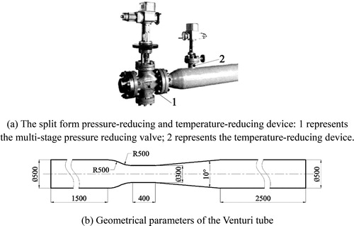
To meet the process requirement, temperature and pressure regulation valves are widely used to regulate the pressure and temperature of superheated steam. The split form is one of the common types of pressure-reducing and temperature-reducing devices, as shown in . Firstly, superheated steam at high pressure and high temperature flows through a multi-stage pressure reducing valve, which is marked as 1 in . Influenced by the throttling element, the pressure of the superheated steam is reduced drastically. In some situations, a Venturi tube is adopted after the multi-stage pressure reducing valve to achieve further pressure reduction. In addition, the temperature-reducing device, which is marked as 2 in , is located in the Venturi tube section. When the superheated steam flows through the Venturi tube, aerodynamic noise might be generated due to the complex turbulent flow, thus the effects of temperature reduction on the aerodynamic noise is attractive. In this investigation, superheated steam at high temperature flows through a Venturi tube. The Venturi tube flow channel is symmetrical, so the geometry model is taken as half of the flow channel, and the geometrical parameters are shown in . The Venturi tube is placed in a straight circular tube flow channel with a radius of 500 mm. The projection picture of the confluent section of the Venturi tube consists of two circular arcs with a radii of 500 mm. The throat diameter and length are 300 mm and 400 mm, respectively. The angle of the Venturi tube divergent section is 10°.
Figure 1. Structure model.
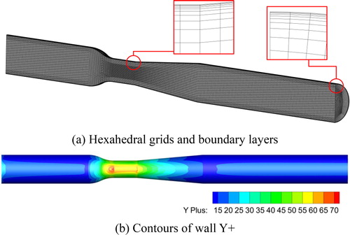
The Venturi tube flow channel geometry model is discretized by hexahedral grids. As depicted in , the area near the tube wall has 5 layers of boundary layer grids to ensure that the wall Y + is in a proper range. When the height of the first layer of the boundary layer grid is 0.2 mm, the value of Y + ranges from 15 to 70 as shown in , and this is acceptable.
Figure 2. Discretization of the geometry model.
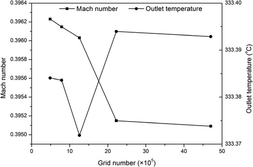
The grid number affects the accuracy of numerical simulation significantly, so a grid independence test was conducted. The average outlet temperature and the average Mach number at the middle cross section of the Venturi tube throat were extracted to assess the independence of grid number and the numerical simulation accuracy. depicts that there is only a small influence of the grid number on the average outlet temperature and the average Mach number at the middle cross section of the Venturi tube throat, when the grid number is larger than 2.2 × 10⁵. In this investigation, the geometry model has 2.3 × 10⁵ grids, which can ensure reasonable accuracy of the numerical simulations.
Figure 3. Grid independence test.
3. Numerical methods and boundary conditions
The superheated steam flows through the Venturi tube at a high speed, and the maximum Mach number is larger than 0.3. The superheated steam should be treated as compressible gas and the numerical simulations are solved by a density-based steady solver. First of all, the governing equations must be solved. In this study, there is no phase transition, and it is a steady state numerical simulation, thus the mass conservation equation is expressed as EquationEq. (1)(1)
(1) :
(1)
(1)
where, ρ is the fluid density, and
is the velocity vector.
The momentum conservation equation reflects the relationship between the forces and momentum increment of the fluid. It is expressed as EquationEq. (2)(2)
(2) [Citation33]:
(2)
(2)
where, p is the static pressure, μ is the molecular viscosity, I is the unit tensor,
and
are the gravitational body force and external body forces, respectively.
In the simulations, the flow channel wall was set to different thermal conditions. The heat was transferred between the superheated steam and the flow channel wall, due to the temperature difference. Thus the energy equation is solved:
(3)
(3)
where, k is the fluid thermal conductivity, and cp is the specific heat of the fluid.
The flow in the Venturi tube is turbulent as the Reynolds number is larger than 107, and the standard k-epsilon turbulence model is selected. The broadband noise source model, derived by Proudman [Citation34] and re-derived by Lilley [Citation35], is used to analyze the acoustic power in the flow channel. In this model, the acoustic power due to the unit volume of isotropic turbulence is expressed by the following equation:
(4)
(4)
where, PA is the acoustic power, α is the model constant, u and l are the turbulence velocity and the turbulence length scale, respectively, and c is the speed of sound. In terms of the k-epsilon model, EquationEq. (4)
(4)
(4) can be rewritten as:
(5)
(5)
where αε is set as 0.1 based on the calibration of Sarkar and Hussaini [Citation36], k is the turbulent kinetic energy, and ε is the turbulent dissipation rate.
The acoustic power can also be expressed in acoustic power level, which is computed from the following equation:
(6)
(6)
where Pref is the reference acoustic power, which is 10−12 W/m3 by default.
Concerning the boundary conditions, the inlet is set as a mass-flow-inlet, where the mass flow is 5.5 kg/s and the temperature is 623 K. The outlet is set as a pressure outlet with the pressure 105 Pa. It is emphasized that the operating pressure is 105 Pa. The symmetry boundary condition is selected for the symmetry surface. Other surfaces are set as walls. The straight tube wall is adiabatic. Two thermal conditions of the Venturi tube wall are considered. In one thermal condition, the Venturi tube wall is adiabatic, while in the other condition the Venturi tube wall temperature changes from 403 K to 583 K.
The superheated steam in this investigation has high temperature and low pressure, and the interaction between the gas molecules can be ignored, so the ideal gas model is adopted. The density of the superheated steam is calculated by the following equation, which is derived from the ideal gas state equation.
(7)
(7)
where, ρ0 is the density, p is the pressure, Me is the relative molecular mass of the gas, R is the molar gas constant, and T is the temperature.
4. Results and discussion
4.1. Adiabatic Venturi tube wall
shows the average pressures (absolute pressure) and temperatures at various cross sections of the flow channel, in which the starting point of the throat is located at the origin of the coordinate z. The pressure and temperature of the superheated steam decrease at the Venturi tube.
Figure 4. Average pressures and temperatures at various cross sections of the flow channel.
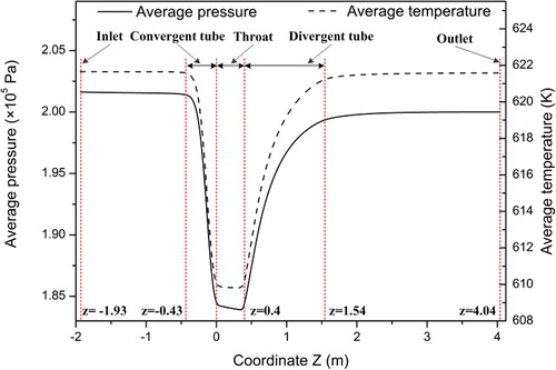
The cross section area of the flow channel decreases sharply at the Venturi tube, so that the flow velocity of the superheated steam increases, and the kinetic energy increases as well. The total energy of the superheated steam decreases, as a result of the local flow resistance of the Venturi tube. As is well known, the total energy of a gas includes internal energy, mechanical energy and potential energy. The change in total energy can be expressed as follows:
(8)
(8)
where Δ represents the change in each parameter, e is the total energy, u is the internal energy, ek is the kinetic energy, and ep is the potential energy. The flow channel is horizontal, so the change in potential energy can be ignored. Then the change in internal energy is expressed as:
(9)
(9)
Because the total energy decreases while the kinetic energy increases, the internal energy decreases. For an ideal gas, the internal energy represents the internal kinetic energy of the thermal motion of the gas molecules, which is indicated by temperature. This is the reason why the temperature of the superheated steam decreases at the Venturi tube.
For the average pressure, the relative difference between the maximum and minimum values is 8.05%, and for the average temperature, the relative difference between the maximum and minimum values is 1.91%, which can be found from . At adiabatic condition, there is a marginal change in temperature, so the parameters related to temperature change slightly.
The Mach number is an index used to describe the characteristics of a gas flow. It is the ratio of the gas flow velocity to the local sound speed, as EquationEq. (10)(10)
(10) shows.
(10)
(10)
where, cf is the gas flow velocity. The sound traveling in gases is approximately an adiabatic process, and the local sound speed, which can be determined by EquationEq. (11)
(11)
(11) , is related to the gas properties.
(11)
(11)
where κ is the isentropic exponent, which may depend on temperature. EquationEquation (10)
(10)
(10) can be rewritten as:
(12)
(12)
EquationEquation (12)(12)
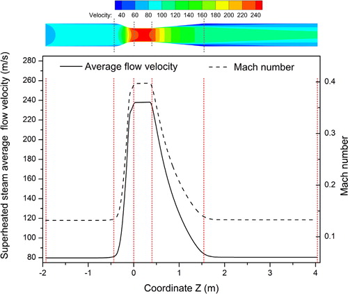
(12) reflects that the Mach number is influenced by temperature and gas flow velocity. Taking into account the small change in temperature at adiabatic condition, the superheated steam flow velocity affects the change of the Mach number along the coordinate z more significantly. As shown in , the solid line represents the superheated steam average flow velocity along the coordinate z. The average flow velocity increases in the convergent tube, where the flow channel diameter decreases, and decreases in the divergent tube, where the flow channel diameter increases. The dashed line represents the Mach number along the coordinate z. It is found that the Mach number changes in a trend consistent with the average flow velocity.
Figure 5. Superheated steam flow velocity and Mach number.
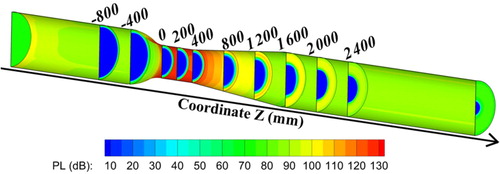
When flowing through the Venturi tube, the superheated steam is disturbed, and the aerodynamic noise might be generated. shows the contours of the acoustic power level. It is found that the acoustic power level at the center of the flow channel is low, in fact less than 10 dB. At a certain cross section, the acoustic power level at the tube wall is larger than at the center. In the whole flow channel, the maximum acoustic power level is located at the wall of the throat entrance, and is above 130 dB. In cross sections at the divergent tube and the downstream straight tube, the maximum acoustic power occurs in the area near the tube wall, and this area is broadened along the coordinate z.
Figure 6. Contours of acoustic level.
By substituting EquationEq. (11)(11)
(11) into EquationEq. (5)
(5)
(5) , the formula used to calculate the acoustic power can be written as:
(13)
(13)
According to EquationEq. (13)(13)
(13) , the acoustic power is affected by the turbulent dissipation rate ε, the turbulent kinetic energy k, the gas density ρ0, the isentropic exponent κ, and the temperature T. Among these parameters, κ is related to temperature while ρ0 is related to temperature and pressure. At adiabatic condition, the temperature changes slightly along the coordinate z, and the change of pressure is within 10%, which means that κ and ρ0 have very small effects on the change of the acoustic power. Thus the effects of turbulent flow characteristics, represented by the turbulent dissipation rate ε and the turbulent kinetic energy k, on the change of acoustic power along the coordinate z are more prominent.
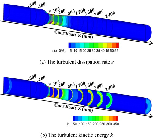
depicts the contours of the turbulent dissipation rate and the turbulent kinetic energy. It is found from that the turbulent dissipation rate is low in the upstream straight tube and the downstream straight tube. At the wall of the back section of the convergent tube, the turbulent dissipation rate increases. Then the maximum turbulent dissipation rate is reached at the wall of the throat entrance, and the maximum value is more than 10 times higher than the minimum value. According to , the turbulent kinetic energy is low in the upstream straight tube. When the superheated steam flows into the convergent tube, due to the contraction of the flow channel, the turbulent kinetic energy increases at the wall of the back section of the convergent tube. The maximum turbulent kinetic energy also occurs at the wall of the throat entrance, for the whole flow channel. However, in the cross sections at the divergent tube and the downstream straight tube, the maximum value is near the wall, and its area is broadened along the coordinate z, which is similar to the contours of the acoustic power level. The maximum turbulent kinetic energy is about 7 times higher than the minimum value. It is found that the acoustic power level at the wall of the throat is a result of the combined influence of the turbulent dissipation rate and the turbulent kinetic energy, and the acoustic power level, at the divergent tube and the downstream straight tube, is mainly affected by the turbulent kinetic energy.
Figure 7. Contours of the turbulent dissipation rate and the turbulent kinetic energy.
4.2. Influence of heat transfer
The above discussions indicate that the temperature has small effects on the change of the aerodynamic noise along the coordinate z at adiabatic condition due to its slight change. In this section, the effects of heat transfer on the aerodynamic noise are investigated. The thermal conditions with different temperatures (Tw) are imposed on the Venturi tube wall, including the convergent tube wall, the throat wall, and the divergent tube wall. Based on the pressure shown in , the temperatures are set as 403 K, 448 K, 493 K, 538 K, and 583 K, respectively, to make sure that the steam is always superheated. The heat was transferred between the superheated steam and the tube wall, because of the temperature difference.
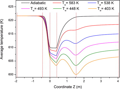
When the superheated steam flows through the channel at different temperatures of the Venturi tube wall, the average steam temperature at the cross sections of the channel is changed. Similar to the adiabatic flow condition, the steam temperature is reduced at the convergent tube and the throat, and then it is increased gradually at the divergent tube, which is shown in . In the upstream straight tube, the tube wall is adiabatic, so the lines of the average temperatures overlap each other. Although the thermal conditions of the tube wall are different in the convergent tube, the average temperatures are similar, which might be explained by the reason that the transition of the convergent tube is smooth. Thus the mixture of the boundary layer flow and the core flow is not violent, and the effects of convective heat transfer on the average temperature are marginal. However, the diameter of the flow channel decreases sharply at the throat, and the flow velocity of the superheated steam increases resulting in generation of turbulence in the flow. With a strong turbulent flow, the influence of the convective heat transfer becomes prominent, and a difference of the average temperatures appears. Due to the cold Venturi tube wall, the minimum temperature at the throat is lower than at the adiabatic thermal condition, and the minimum temperature is reduced with the decrease of the Venturi tube wall temperature. For the adiabatic thermal condition, the average temperature increases along the coordinate z in the divergent tube. However, the average temperature increases in the front section of the divergent tube, and then decreases in the back section of the divergent tube, for a cold Venturi tube wall. When the Venturi tube wall is adiabatic, the change of the average temperature is caused by the variation of the internal energy. For a cold Venturi tube wall, the average temperature is influenced by both the variation of internal energy and the convective heat transfer. Also in the section, where the average temperature increases, the increase of internal energy plays a major role in affecting the change of temperature, while in the section, where the average temperature decreases, the convective heat transfer plays the major role instead. When the superheated steam flows into the downstream tube, the average temperature increases a little, due to the adiabatic tube wall. Finally, the outlet steam temperature decreases with the decrease of the Venturi tube wall temperature.
Figure 8. Average temperatures at various cross sections of the flow channel at different thermal conditions.
The pressure drops of the flow through the channel at different thermal conditions are presented in . The pressure drop decreases with the decrease of the Venturi tube wall temperature. It is noteworthy that compared with the absolute pressure at the inlet and outlet, the differences of the pressure drop are so small that they can be ignored. The Venturi tube wall temperature affects the pressure indistinctively.
Table 1. The pressure drop at different thermal conditions.
According to EquationEq. (7)(7)
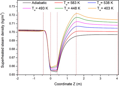
(7) , the density of the superheated steam is directly proportional to pressure, and inversely proportional to temperature. depicts the average density of the superheated steam along the coordinate z at different thermal conditions. The average densities at the upstream straight tube are close to each other, because the upstream straight tube wall is adiabatic. In the convergent tube, the lines of average densities overlap each other due to the almost indistinguishable temperature difference. Influenced by the different average temperatures in the throat and the divergent tube, the differences in densities are gradually apparent. It is found that the superheated steam density increases with the decrease of the Venturi tube wall temperature.
Figure 9. Superheated steam densities along the coordinate Z at different thermal conditions.
The superheated steam average flow velocity is calculated by the following equation:
(14)
(14)
where, F is the mass flow rate, A is the cross section area of the flow channel. At a certain coordinate z, the cross section areas are the same accordingly. With a fixed mass flow rate, the superheated steam flow velocity decreases with the increase of the density. This means that a lower Venturi tube temperature results in a lower flow velocity.
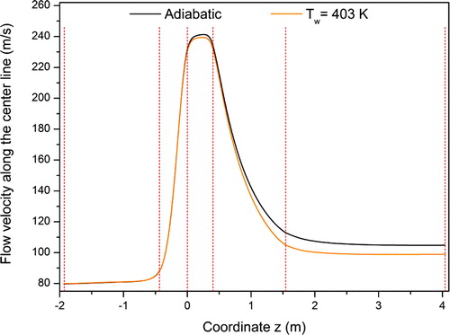
Jet flow is one of the reasons causing aerodynamic noise. When flowing through the Venturi tube, the superheated steam flow velocity increases as the channel diameter decreases, thus a jet flow is formed. The characteristic feature of the jet flow is that the center velocity is higher than the adjacent velocities. As imaged in , the superheated steam flow velocities along the center line of the flow channel are extracted, for which the thermal conditions of the Venturi tube wall are adiabatic and at a temperature of 403 K, respectively. In the upstream straight tube, the tube wall is adiabatic for the two cases and thus the superheated steam flow velocities along the center line are almost identical. The thermal conditions of the tube wall in the convergent section are different, but as the shape transition is smooth and the convective heat transfer of the superheated steam is inefficient, the effects of the tube wall thermal conditions on the flow at the center line are not identical. Thus the difference in the superheated steam flow velocities along the center line is minor. At the throat, the channel cross section is narrowed and the average flow velocity is increased, causing the turbulence of the flow to be intensified, so that the convective heat transfer efficiency becomes higher and the flow at the center line is affected by the tube wall thermal conditions more significantly. As a result, an obvious difference between the superheated steam flow velocities along the center line appears in the throat, and the cold tube wall leads to a lower center velocity. The difference between the superheated steam flow velocities along the center line continues to the divergent tube and the downstream straight tube. According to the above analysis, a cold Venturi tube wall can reduce the superheated flow velocity along the center line and weaken the jet flow, resulting in a reduction of the aerodynamic noise.
Figure 10. The flow velocity along the center line of the flow channel.
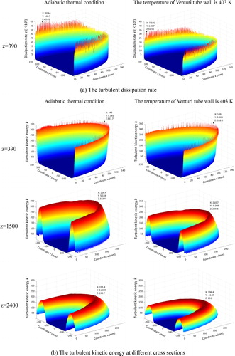
As mentioned in the last section, the turbulence characteristics affect the change of the acoustic power along the coordinate z significantly. A lower flow velocity means a gentler turbulence. From it is evident that the maximum turbulent dissipation rate and turbulent kinetic energy occur at the throat wall, and the turbulent kinetic energy at the divergent tube and the downstream straight tube is reflecting the aerodynamic noise. For the purpose of analyzing the effects of heat transfer on the turbulence characteristics, two cases are compared, one is the adiabatic Venturi tube wall, and the other is a nonadiabatic Venturi tube wall at a temperature of 403 K. shows the turbulent dissipation rate ε in the cross section at the throat (z = 390 mm). In , three cross sections, one at the end of the throat (z = 390 mm), one at the divergent tube (z = 1,500 mm), and the third one at the downstream tube (z = 2,400 mm), are extracted, and their contours of turbulent kinetic energy are shown. According to , the turbulent dissipation rate is extremely high at the wall of the throat. Compared with the adiabatic thermal condition, the maximum turbulent dissipation rate decreases by 1.05 × 10⁷, when the Venturi tube wall temperature is 403 K, which indicates that a lower temperature can reduce the turbulent dissipation rate. shows that at a certain coordinate z position, the maximum turbulent kinetic energy is lower when the Venturi tube wall temperature is 403 K, and the difference is larger at the divergent tube. The differences of turbulent dissipation rate and turbulent kinetic energy reflect that the heat transfer has effects on the turbulence characteristics, so the acoustic power may change with different heat transfer conditions.
Figure 11. The turbulent characteristics at different thermal conditions.
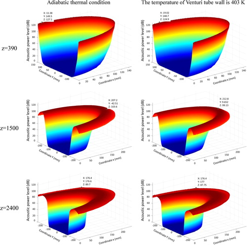
A comparison of the acoustic power levels at the cross sections mentioned above is depicted in . At a certain cross section, the acoustic power level is lower when the Venturi tube wall temperature is 403 K, despite the differences are rather small.
Figure 12. The acoustic power levels at different thermal conditions.
It is found from and Citation12 that the largest acoustic power level in a cross section occurs near the tube wall. As a further investigation, a quantitative analysis about the difference of acoustic power at the tube wall with various Venturi tube wall thermal conditions is conducted, as shown in , where the cases of the adiabatic tube wall and Venturi tube wall temperature at 403 K are considered. In the upstream straight tube, the acoustic power is very low, close to 0. The low acoustic power continues to the front section of the convergent tube. In the back section of the convergent tube, the acoustic power increases sharply, as a result of the contraction of the channel cross section. With the further decrease of the flow channel cross section, the acoustic power peaks before the superheated steam enters the throat. Then the acoustic power decreases in the throat. Further downstream, the acoustic power increases again, due to the abrupt change of the flow channel at the border between the throat and the divergent tube. When the superheated steam flows out of the throat, the acoustic power decreases to a low value, which is close to 0, and the low acoustic power is kept along the downstream straight tube. At different heat transfer conditions, the acoustic power at the tube wall is different in the Venturi tube. The acoustic power is much higher for the adiabatic tube wall. The maximum difference, which is 6.5 W, is reached, when the acoustic power is at the peak.
Figure 13. The acoustic power at the tube wall at different thermal conditions.
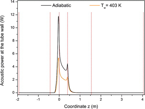
It is emphasized that when the Venturi tube wall temperature is 403 K, the temperature of the superheated steam is reduced by about 20 K. In the real engineering field, spraying water is a common method to cool superheated steam. The heat transfer efficiency is much higher than for convective heat transfer, and the temperature of the superheated steam will be lower. Thus the acoustic power could be reduced more. The method of spraying water to cool the superheated steam will be investigated in a future study.
5. Conclusions
In this investigation, the effects of heat transfer on the aerodynamic noise are studied. Due to the high temperature and low pressure, the superheated steam is treated as an ideal gas. Because of the high flow velocity, the k-epsilon turbulence model is used, and the superheated steam is compressible. Superheated steam flowing through a Venturi tube, one of the main parts in a temperature and pressure regulation valve, at different thermal conditions is analyzed, and the following conclusions are drawn. At adiabatic condition, the change of the steam temperature is slight along the coordinate z. The acoustic power is affected by the turbulence characteristics, represented by the turbulent dissipation rate and the turbulent kinetic energy, prominently. At nonadibatic conditions, for which the Venturi tube wall is cold and the heat was transferred from the superheated steam to the tube wall, thus the steam is cooled. The physical characteristics and turbulent flow performance are changed by the heat transfer conditions. By comparing the acoustic power level, the flow velocity along the center line and the acoustic power at the tube wall, it is found that a lower tube wall temperature, resulting a more intensive convective heat transfer condition, weakens the aerodynamic noise.
Additional information
Funding
References
- X. Han, Z. Han, W. Zeng, L. Peng, and J. Qian, “Numerical simulation of wet steam transonic condensation flow in the last stage of a steam turbine,” Int. J. Numer. Methods Heat Fluid, vol. 28, no. 10, pp. 2378–2403, 2018. DOI: 10.1108/HFF-10-2017-0415.
- W. Adamczyk, P. Kozolub, G. Węcel, and A. Ryfa, “Simulations of the PC boiler equipped with complex swirling burners,” In.t J. Numer. Methods Heat Fluid, vol. 24, no. 4, pp. 845–860, 2014. DOI: 10.1108/HFF-02-2013-0067.
- N. D. Pham et al., “Quality of plant-based food materials and its prediction during intermittent drying,” Crit. Rev. Food Sci. Nutr., vol. 59, no. 8, pp. 1197–1211, 2019. DOI: 10.1080/10408398.2017.1399103.
- T. Väisänen, P. Kilpeläinen, V. Kitunen, R. Lappalainen, and L. Tomppo, “Effect of steam treatment on the chemical composition of hemp (Cannabis sativa L.) and identification of the extracted carbohydrates and other compounds,” Ind. Crops Prod., vol. 131, pp. 224–233, 2019. DOI: 10.1016/j.indcrop.2019.01.055.
- J. Tao et al., “An experimental and numerical study of regulating performance and flow loss in a v-port ball valve,” J. Fluids Eng., vol. 142, no. 2, 2020. DOI: 10.1115/1.4044986.
- J. Y. Qian et al., “Analysis of fouling in six-start spirally corrugated tubes,” Heat Transfer Eng., vol. 40, pp. 1–16, 2019. DOI: 10.1080/01457632.2019.1675246.
- C. Yang et al., “Heat transfer study of a hybrid smooth and spirally corrugated tube,” Heat Transfer Eng., vol. 1–9, Dec. 2019. DOI: 10.1080/01457632.2019.1699292.
- J. Qian et al., “A geometric study on shell side heat transfer and flow resistance of a six-start spirally corrugated tube,” Numer. Heat Transfer, Part A, vol. 73, no. 8, pp. 565–582, 2018. DOI: 10.1080/10407782.2018.1459381.
- L. Luo et al., “Convergence angle and dimple shape effects on the heat transfer characteristics in a rotating dimple-pin fin wedge duct,” Numer. Heat Transfer, Part A, vol. 74, no. 10, pp. 1611–1635, 2018. DOI: 10.1080/10407782.2018.1543920.
- S. Wang et al., “Heat transfer characteristics of a dimpled/protrusioned pin fin wedge duct with different converging angles for turbine blades,” Numer. Heat Transfer, Part A, vol. 76, no. 5, pp. 369–392, 2019. DOI: 10.1080/10407782.2019.1630235.
- J. Y. Qian, Z. Wu, Q. K. Zhang, Z. J. Jin, and B. Sundén, “Heat transfer analysis on dimple geometries and arrangements in dimple jacketed heat exchanger,” HFF, vol. 29, no. 8, pp. 2775–2791, 2019. DOI: 10.1108/HFF-12-2018-0792.
- Z. Cao, Z. Wu, H. Luan, and B. Sundén, “Numerical study on heat transfer enhancement for laminar flow in a tube with mesh conical frustum inserts,” Numer. Heat Transfer, Part A, vol. 72, no. 1, pp. 21–39, 2017. DOI: 10.1080/10407782.2017.1353386.
- T. W. Kim and T. S. Park, “Size effect on compressible flow and heat transfer in microtube with rarefaction and viscous dissipation,” Numer. Heat Transfer, Part A, vol. 76, no. 11, pp. 871–888, 2019. DOI: 10.1080/10407782.2019.1673106.
- Y. Wang, Y. Hu, Q. Huang, and Y. Cui, “Transient heat transfer study of direct contact condensation of steam in spray cooling water,” Trans. Tianjin Univ., vol. 24, no. 2, pp. 131–143, 2018. DOI: 10.1007/s12209-017-0106-6.
- A. `, W. Lerch, and R. Heimrath, “Heat pump condenser and desuperheater integrated into a storage tank: model development and comparison with measurements,” Appl. Therm. Eng., vol. 102, pp. 465–475, 2016. DOI: 10.1016/j.applthermaleng.2016.04.010.
- E. Vahid and G. Mofid, “Two-dimensional modeling of water spray cooling in superheated steam,” Therm. Sci, vol. 12, no. 2, pp. 79–88, 2008.
- R. Kouhikamali, H. Hesami, and A. Ghavamian, “Convective heat transfer in a mixture of cooling water and superheated steam,” Int. J. Therm. Sci., vol. 60, pp. 205–211, 2012. DOI: 10.1016/j.ijthermalsci.2012.05.012.
- E. Rahimi, S. Torfeh, and R. Kouhikamali, “Numerical study of counter-current desuperheaters in thermal desalination units,” Desalination, vol. 397, pp. 140–150, 2016. DOI: 10.1016/j.desal.2016.06.028.
- Z. J. Jin, C. Qiu, C. H. Jiang, J. Y. Wu, and J. Y. Qian, “Effect of valve core shapes on cavitation flow through a sleeve regulating valve,” J. Zhejiang Univ. Sci. A, vol. 21, no. 1, pp. 1–14, 2020. DOI: 10.1631/jzus.A1900528.
- S. S. Rodrigues and A. C. Marta, “On addressing wind turbine noise with after-market shape blade add-ons,” Renew. Energy, vol. 140, pp. 602–614, 2019. DOI: 10.1016/j.renene.2019.03.056.
- C. Xu, Y. Mao, and Z. Hu, “Control of cylinder wake flow and noise through a downstream porous treatment,” Aerosp. Sci. Technol., vol. 88, pp. 233–243, 2019. DOI: 10.1016/j.ast.2019.03.027.
- J. Y. Qian, M. R. Chen, X. L. Liu, and Z. J. Jin, “A numerical investigation of the flow of nanofluids through a micro Tesla valve,” J. Zhejiang Univ. Sci. A, vol. 20, no. 1, pp. 50–60, 2019. DOI: 10.1631/jzus.A1800431.
- J. Y. Qian, M. R. Chen, Z. X. Gao, and Z. J. Jin, “Mach number and energy loss analysis inside multi-stage Tesla valves for hydrogen decompression,” Energy, vol. 179, pp. 647–654, 2019. DOI: 10.1016/j.energy.2019.05.064.
- L. Li, P. Liu, Y. Xing, and H. Guo, “experimental investigation on the noise reduction method of helical cables for a circular cylinder and tandem cylinders,” Appl. Acoust., vol. 152, pp. 79–87, 2019. DOI: 10.1016/j.apacoust.2019.03.027.
- A. Bodling and A. Sharma, “Numerical investigation of noise reduction mechanisms in a bio-inspired airfoil,” J. Sound Vib., vol. 453, pp. 314–327, 2019. DOI: 10.1016/j.jsv.2019.02.004.
- G. Romani and D. Casalino, “Rotorcraft blade-vortex interaction noise prediction using the Lattice-Boltzmann method,” Aerosp. Sci. Technol., vol. 88, pp. 147–157, 2019. DOI: 10.1016/j.ast.2019.03.029.
- J. Y. Qian, C. W. Hou, J. Y. Wu, Z. X. Gao, and Z. J. Jin, “Aerodynamics analysis of superheated steam flow through multi-stage perforated plates,” Int. J. Heat Mass Transfer, vol. 141, pp. 48–57, 2019. DOI: 10.1016/j.ijheatmasstransfer.2019.06.061.
- E. Talay and A. Altinisik, “The effect of door structural stiffness and flexural components to the interior wind noise at elevated vehicle speeds,” Appl. Acoust., vol. 148, pp. 86–96, 2019. DOI: 10.1016/j.apacoust.2018.12.005.
- L. J. Ayton and P. Chaitanya, “An analytical and experimental investigation of aerofoil–turbulence interaction noise for plates with spanwise-varying leading edges,” J. Fluid Mech., vol. 865, pp. 137–168, 2019. DOI: 10.1017/jfm.2019.78.
- C. P. Arroyo, T. Leonard, M. Sanjosé, S. Moreau, and F. Duchaine, “Large Eddy simulation of a scale-model turbofan for fan noise source diagnostic,” J. Sound Vib., vol. 445, pp. 64–76, 2019. DOI: 10.1016/j.jsv.2019.01.005.
- M. Zhang and A. Frendi, “Effect of airfoil leading edge waviness on flow structures and noise,” Int. J. Numer. Methods Heat Fluid, vol. 26, no. 6, pp. 1821–1842, 2016. DOI: 10.1108/HFF-04-2015-0143.
- A. Frendi and M. Brown, “Flow structures and noise from a supersonic impinging jet,” Int. J. Numer. Methods Heat Fluid, vol. 26, no. 8, pp. 2509–2527, 2016. DOI: 10.1108/HFF-05-2015-0174.
- G. K. Batchelor, An Introduction to Fluid Dynamics, Cambridge, England: Cambridge University Press, 1967.
- I. Proudman, “The generation of noise by isotropic turbulence,” Proc. R. Soc. A, vol. 214, pp. 119–132, 1952.
- G. M. Lilley, “The radiated noise from isotropic turbulence revisited,” Theoret. Comput. Fluid Dyn., vol. 6, no. 5–6, pp. 281–301, 1994. DOI: 10.1007/BF00311842.
- S. Sarkar and M. Y. Hussaini, “Computation of the sound generated by isotropic turbulence,” In NASA Contract Report, Hampton, VA: NASA Langley Research Center, 1993, pp. 93–74.