
 ?Mathematical formulae have been encoded as MathML and are displayed in this HTML version using MathJax in order to improve their display. Uncheck the box to turn MathJax off. This feature requires Javascript. Click on a formula to zoom.
Abstract
In this work, the effects of thermal buoyancy and rotation angle on the hydrodynamics and mixed convection heat transfer characteristics over four heated identical square cylinders placed in a parallel horizontal channel are numerically studied. For the flow field, the Lattice Boltzmann method (LBM) with multiple relaxation time collision operator (MRT) is implemented and the Bhatnagar-Gross-Ktook collision operator (BGK) is adopted for the thermal field simulation. The distance between two adjacent square cylinders is fixed for a parametric study and a uniform velocity is imposed at the inlet region. Ranges of the influence parameters are defined as: α = 45°, 90°, 120°; 50 ≤ Re ≤ 150; 0 ≤ Ri ≤ 0.5. Several flow and heat transfer parameters including the time-averaged lift/drag coefficients, the global time-averaged Nusselt number and the distributions of local Nusselt number are analyzed, respectively. The vorticity and isotherm patterns are also plotted to illustrate the visual disturbance of the thermal buoyancy and the rotation angle on the flow and thermal fields. Numerical results show that the flow and thermal patterns for all arrangements become disordered and nonsystematic with the introduction of thermal buoyancy, and the thermal pattern for the downstream cylinders has an upward drift in the wake region. The time-averaged lift coefficient for each square cylinder is relatively sensitive to the influence parameters and the arrangement, and it is always less than zero when the Richardson number is not equal to zero. The global time-averaged Nusselt number is directly proportional to the Reynolds number and Richardson number, and the local Nusselt numbers on the front and rear faces for each square cylinder reach a maximum and minimum, respectively. It is also observed that the distribution of local Nusselt number for all rotation angles is intensively affected by the thermal buoyancy.
1. Introduction
Interference problems around multiple bluff bodies are common engineering problems, including heat exchanger tube arrays, offshore structures and bridge piers. When the flow passes through the multiple bluff bodies at a certain speed, vortices can be generated alternately on the two sides from the surface of the structure, and the pressure on the bluff body structure is asymmetrical in the flow field. Thus, an alternating load is generated on multiple bluff bodies, and it is easy to produce vortex-induced vibration which causes fatigue damage and further affects the equipment life time. Moreover, mixed convection heat transfer exists in this situation with flow past multiple bluff bodies. The mutual interactions in the wake flow result in complex flow patterns, and if the buoyancy-driven cross flow also is considered, the flow structure influence might become more intricate. Hence, exploring the mechanism of flow and heat transfer of multiple cylinders is still a significant research topic under the consideration of thermal buoyancy.
At present, there are several numerical and experimental investigations about the flow and heat transfer over bluff bodies in a parallel horizontal or vertical channel. It is well known that the flow and thermal patterns behind a single cylinder or two cylinders are relatively simple. Thus a large number of experimental [Citation1–3] and numerical investigations mainly concentrated on an isolated single cylinder or two cylinders for pure forced convection and mixed convection. Particularly for the pure forced convection, several adjustable parameters such as the transverse separation ratio, the arrangement of circular or square cylinders, the attack angle, the blockage ratio, the power-law index, the Prandtl number, the Reynolds number and different inlet or wall boundary conditions, are regarded as vital factors to explore the flow and heat transfer mechanisms [Citation4–7].In addition to the above adjustable parameters, the thermal buoyancy is also a crucial factor since the vortex patterns and the interactions between adjacent cylinders can change dramatically and further affect the flow dynamics and heat transfer efficiency [Citation8–14]. For example, Sanyal and Dhiman [Citation8] investigated the influences of the transverse gap ratio (0.7–10) and the Richardson number (0–1) for a flow through a pair of side-by-side square cylinders, and further gave a detailed explanation of the wake interaction phenomenon within a buoyancy-driven cross flow. They found that the phenomena of the early fluid instability and the early formation of flow regimes could appear as the transverse gap ratio is relatively small for mixed convection at Re = 40 and Pr = 50. They also discussed the influence of thermal stratification of shear layers at lower Reynolds numbers and analyzed the phenomenon of “baroclinic production” during the transport of the vorticity process [Citation9]. They mainly focused on the interpretation of flow fields and heat transfer phenomena at varying transverse gap ratio and thermal buoyancy in case of low Reynolds number. Compared to the conventional simulation methods, Monfared et al. [Citation10] adopted the lattice Boltzmann method to investigate the buoyancy-driven cross flow phenomena over three tandem inline square cylinders in a parallel horizontal channel, where the surface of the cylinder imposes a constant heat flux boundary condition which is different from the constant temperature on each cylinder surface. They discussed the effects of a modified parameter on the flow and heat transfer characteristics by modifying the definition of conventional Richardson number and found that the addition of thermal buoyancy rapidly accelerates the occurrence of vortex shedding, and the modified Richardson number affects the frequency of vortex shedding for varying Reynolds number to some extent. It can be easily observed that the introduction of thermal buoyancy causes instability and complexity of the flow and thermal fields, and further increases the difficulty of the overall research and mechanism analysis. Unfortunately, the patterns behind the multiple cylinders based on the thermal buoyancy (i.e., mixed convection) can be rarely found in the existing literature.
Actually, multiple cylinders are more likely to appear in practical engineering applications. The hydrodynamic and thermal transport characteristics for multiple cylinders encounter tremendous challenges due to the fairly complicated dynamic interaction in the wake flow and relatively scarce studies in the aspects of multiple cylinders are available. To investigate the effects of some crucial factors on the change of flow patterns and explore the intrinsic influence mechanism, a large amount of experimental measures of four cylinders in cross flow were carried out by Lam et al. [Citation15–18], which were mainly concentrated on the effects of the attack angle α and the spacing ratio between two adjacent cylinders at different Reynolds numbers. There are several conclusions given by the results of experiments, like the pressure distribution, the forces variation and shedding frequencies of the cylinder surface and there are strongly affected by the development of free shear layers and the distribution of the wake structure of the cylinders at extremely higher Reynolds number. The impingement of the incoming vortices on the cylinders and the generation of a jet flow between the stagnation wake of the upstream and downstream cylinders are regarded as two dominant factors resulting in flow-induced vibration for four cylinders at Re = 200. Additionally, the effects of different spacing ratios and attack angles were discussed in detail and it was found that there were quite different mechanisms of flow-induced vibration. Different from the cylindrical object of the above researches, Liu et al. [Citation19] focused on the experimental investigation of the flow characteristics for four square cylinders and discussed the effects of the spacing ratio and incidence angle on the flow dynamics at subcritical Reynolds numbers, and found that the interference between four square cylinders varies with the spacing ratio and incidence angle. Several similar experimental tests [Citation20, Citation21] and numerical studies [Citation22–25] on multiple cylinders also discussed the flow characteristics for pure forced convection. A lot of results fully confirm that the flow characteristics of multiple cylinders strongly depend on the overall arrangement and the attack angle because the incoming flow through differently arranged multiple cylinders structure can change the stability and complexity of the flow fields and enhance the interactions between cylinders. Unfortunately, the above research only focused on the flow dynamics of four cylinders under pure forced flow, while the heat transfer characteristics for four square cylinders were omitted.
Based on the above description, firstly, compared to pure forced convection or free convection, the exploration of flow and heat transfer for mixed convection is much more difficult due to the addition of thermal buoyancy. Furthermore, the situation is more complex under the consideration of heat transfer. Also because a mixed convection heat transfer always appears in a practical engineering application it is worth studying. Secondly, even though similar features can be observed for circular and square cylinders, the flow and thermal patterns can produce completely different phenomena due to the existence of a sharp apex angle. In conclusion, a study of mixed convection heat transfer for multiple square cylinders should be taken seriously.
It should be noted that LBM has better performance than conventional CFD methods because LBM has the excellent capability of handling complex flow geometries and does not take additional time to solve the pressure term and the Laplace Equationequation [6(6)
(6) , Equation10]
(10)
(10) . More subtle phenomena can be captured by the mesoscopic LBM, this provides a further basis for revealing the mechanism. In this study, the arrangement of multiple square cylinders and the thermal buoyancy are considered, respectively, thus LBM is appropriate to investigate the mechanisms of flow and heat transfer for four square cylinders under the buoyancy-driven cross flow, where the MRT model and the BGK model are applied in the flow field and thermal field, respectively. Besides, this work intends to further reveal deeper phenomena and broaden the performance of LBM in these aspects.
2. Mathematical formulation
2.1. Problem description
A two-dimensional, laminar and incompressible flow is assumed in a parallel adiabatic horizontal channel with air as the working fluid (Pr = 0.71). A uniform free stream velocity u∞ and a constant temperature TW are imposed to the channel inlet region and the surfaces of four heated square cylinders, respectively. Besides, the viscous dissipation in the energy equation is ignored, and the Boussinesq approximation is assumed to be effective [Citation12].
shows the two-dimensional mixed convection physical model. Four identical square cylinders of side length ‘D’ arranged in a square track are placed in a parallel straight channel. To keep consistency with literature and to ensure that the occurrence of vortex shedding can be observed for a range of 50≤Re ≤ 150 and 0≤Ri ≤ 0.5, the distance between the center points of two adjacent square cylinders is ‘5D’, that is, the gap between the sidewall surfaces of two adjacent square cylinders is fixed at ‘4D’. The upstream distance is set to Lu = 5 D based on the purpose of enabling comparison with the literature [Citation12]. The intersection of the diagonal of the four square cylinders is located in the centerline of the channel. Since the effect of the arrangement of four square cylinders on the flow and heat transfer is mainly highlighted in this work when the thermal buoyancy is imposed, the selection of the above parameters is reasonable to explore the interactions between the four square cylinders. The arrangement of the square cylinders is varied by rotation a certain angle clockwise with the intersection as the base point, as shown in .
Figure 1. Schematic description of the flow past four heated square cylinders: (a) computational domain used in the illustration of mixed convection flow and heat transfer; (b) different arrangement angles for the four heated square cylinders.
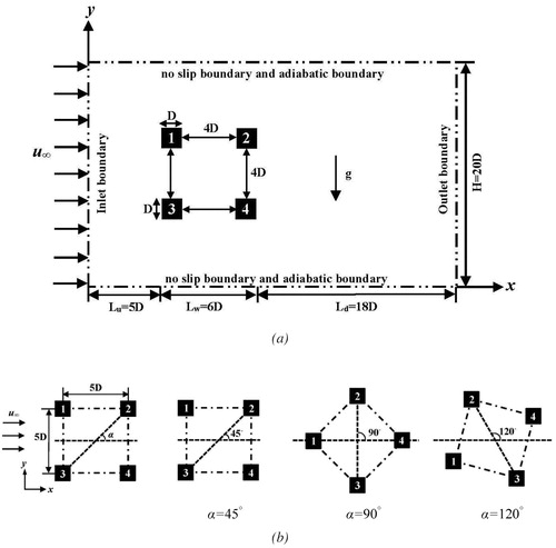
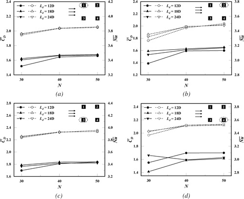
Figure 2. The independence analysis of the number of lattice units (N) and the downstream length Ld on time-averaged drag coefficient and Nusselt number for the rotation angle α = 45° at Re = 100 and Ri = 0.25: (a) square cylinder 1; (b) square cylinder 2; (c) square cylinder 3; (d) square cylinder 4; where the solid and the hollow symbols represent the values of the time-averaged drag coefficient and the time-averaged Nusselt number, respectively.
2.2. Conservation equations
The following nondimensional conservation equations, including the continuity, momentum and energy equations, are used to reveal the two-dimensional incompressible mixed convection based on the Boussinesq approximation [Citation12]:
Continuity equation:
(1)
(1)
Momentum equations:
(2)
(2)
(3)
(3)
Energy equation:
(4)
(4)
It should be noted that u and v represent the dimensionless velocity components with respect to the directions of the flow and perpendicular to the flow, respectively. p and θ refer to the dimensionless pressure and temperature. Additionally, the above nondimensional conservation equations can be characterized by the dimensionless numbers including the Reynolds number Re (= u∞D/ν), the Prandtl number Pr (= ν/γ), the Richardson number Ri (= Gr/Re2) and the Grashof number Gr (= gβ(TW-T∞)D3/ν2). Here, ν and γ represent the kinematic viscosity and the thermal diffusivity, respectively. g is the gravitational acceleration, and β is the thermal expansion coefficient.
2.3. Lattice Boltzmann method (LBM)
In the LBM, the Bhatnagar-Gross-Ktook (BGK) model [Citation26] has become the most widely used collision operator due to its simple form and easy implementation. However, the BGK model becomes numerically unstable when the dimensionless parameter τ is close to 0.5. The multiple relaxation time (MRT) model [Citation27] alleviates the issue of numerical instability of LBM to some extent. The MRT model transforms the collision of velocity space into a collision of moment space through a linear transformation so that the resulting variables have physical meaning, and the inverse transformation is performed to the velocity space for the migration process after the collision is completed in the moment space. Compared with the BGK model, the MRT model is relatively complex for the determination of multiple relaxation times. In the present study, the MRT model with the D2Q9 lattice model only is applied to the density distribution function to ensure stability and accuracy of the numerical scheme, while the energy distribution function adopts the BGK model with the D2Q9 lattice model to reduce the demand of CPU consumption.
2.3.1. LB equation for the velocity field
Based on the consideration of the effect of thermal buoyancy, the evolution equation can be written as
(5)
(5)
where fi and Ωi represent the discrete distribution function with the discrete velocity ei and the discrete collision operator, respectively. In the above EquationEq. (5)
(5)
(5) , the BGK model has poor stability in simulation of the flow and heat transfer from four square cylinders under the influence of the thermal buoyancy when 50≤Re ≤ 150. Hence, the MRT collision operator is introduced to describe the LB equation, which has good stability compared with the BGK model. The collision operator of the MRT model is given by the following
(6)
(6)
where the diagonal relaxation matrix S and the transformation matrix M can be defined as
(7)
(7)
(8)
(8)
Since the determination of the appropriate relaxation times affects the stability of the model, the relaxation times for the above definition (7) based on model validation and literature research can be selected as, τρ = τj = 1, τe = τζ = 1.4, τq = 1.2, and the dimensional relation time τf for velocity field can be evaluated by the following kinematic viscosity,
(9)
(9)
where cs is the speed of sound related to the lattice speed c. The definitions of cs and c are given by cs = (c2/3)1/2 and c = Δx/Δt, and the lattice spacing Δx and the time step Δt are set as a unit in the present study.
It should be noted that the transformation matrix M projects the discrete distribution functions fi onto the moment space
(10)
(10)
where
(11)
(11)
Based on the D2Q9 lattice model, the macroscopic moments and the nonconserved equilibrium function are given by
(12)
(12)
(13)
(13)
where
ux and uy are the x and y components of velocity vector u, the velocity vectors eix and eiy are acting in the x-direction and y-direction, respectively.
The following form of the discrete lattice velocity ei with the D2Q9 lattice model in this work is written as
(14)
(14)
For the MRT collision operator Equation(6)(6)
(6) , fieq is the equilibrium distribution function as follows
(15)
(15)
where ωi is the weight coefficient, with ω0 = 4/9, ωi = 1/9 for i = 1–4 and ωi = 1/36 for i = 5–8. To highlight the effects of thermal buoyancy in the case of mixed convection, an extra buoyancy term (Boussinesq term) Fi acting in the direction perpendicular to the flow is added to the right-hand side of the LB collision Equationequation (5)
(5)
(5) due to the flow driven by the temperature gradient. Moreover, the problem studied in the present work does not consider the effect of radiation heat transfer. Using the Boussinesq approximation, the force term Fi can be written as
(16)
(16)
where θ is the dimensionless temperature of the fluid.
According to the discrete distribution function, the macroscopic variables, including density and velocity, can be given by
(17)
(17)
2.3.2. LB equation for temperature field
The selection of the collision operator plays a significant role in the stability of the numerical scheme. The density distribution function with the multiple relaxation time collision operator in the flow field is applied to solve the momentum equation to ensure accuracy and stability. However, based on numerical tests, the Bhatnagar-Gross-Ktook collision operator is satisfactory to maintain the stability in the temperature field, and it is applied in the temperature distribution function gk to solve the energy equation for better exploring the variable characteristics of the temperature field. The discrete distribution function in the temperature field can be given by
(18)
(18)
where the dimensionless relaxation time τg can be assessed by the following thermal diffusion coefficient,
(19)
(19)
Here, gieq is the temperature equilibrium distribution function as follows
(20)
(20)
The following macroscopic temperature θ can be evaluated via the temperature distribution function,
(21)
(21)
2.3.3. Boundary conditions
The precise application of boundary conditions is comparatively crucial to the stability and accuracy of LBM simulations. Different from the conventional boundary conditions imposed by Navier-Stokes equations, the values of the density distribution function and the energy distribution function in LBM are used to reflect the imposed boundary conditions. Different boundary conditions are adopted to simulate the flow and heat transfer past four heated square cylinders more precisely.
Inlet boundary condition: In the flow field, a free steam uniform velocity u∞ is imposed at the inlet. The inward distribution functions of the boundary region need to be calculated according to the appropriate equation for a given boundary condition. Based on the consideration of three unknown functions f1, f5 and f8, the following boundary conditions proposed by Zou and He [Citation28] are considered
(22)
(22)
(23)
(23)
(24)
(24)
(25)
(25)
In addition, a constant temperature (θ = 0) of the temperature field is applied at the inlet based on the consideration of the dimensionless temperature. The unknown temperature distribution functions g1, g5, g8 are given by
(26)
(26)
Top, bottom and the surfaces of square cylinders boundary conditions: The no-slip boundary condition is imposed at the walls, including the top, bottom, and the surfaces of four square cylinders. The bounce-back scheme [Citation29] in LBM is applied to simulate the no-slip boundary condition on the solid surface of the flow over cylinders. The boundary conditions are given by
(27)
(27)
where i and opp(i) satisfy the condition ei = −eopp(i), where eopp(i) is the lattice velocity in the opposite direction of ei.
In the temperature field, the top and bottom walls are adiabatic, which means that the adiabatic boundary condition ∂θ/∂y = 0 is imposed. A constant wall temperature (θ = 1) is kept at the surfaces of the four square cylinders. The corresponding boundary conditions of the top and bottom walls are given by
(28)
(28)
(29)
(29)
The boundary condition of the surface of each cylinder is written as
(30)
(30)
Outlet boundary condition: The open boundary condition [Citation29] is used at the outlet region due to the unknown values of outlet velocity and pressure. Here, the second-order interpolation scheme is adopted to solve the unknown distribution functions in the present work, and the unknown distribution functions can be found as follows:
(31)
(31)
Furthermore, the temperature distribution functions adopt a similar manner to set the outlet boundary condition.
(32)
(32)
2.3.4. Dimensionless variables
In the LBM, the following definitions of dimensionless variables are given to explore the flow and heat transfer characteristics better.
Reynolds number: The Reynolds number (Re) is defined as
(33)
(33)
where the characteristic length D is related to the lattice number N, and u∞ represents the characteristic velocity.
Drag and lift coefficients: The momentum exchange method [Citation30, Citation31] is used to solve the evaluation of the total resultant force Fr = (FD, FL), where FD and FL represent the drag and the lift forces. Correspondingly, the drag coefficient CD, the lift coefficient CL and the total force Fr are given by
(34)
(34)
(35)
(35)
Here, xb is the boundary node of the square cylinder. w(xb+eopp(i)Δt) is seen as an indicator to make sure that the value of the node is equal to 1 at the solid zone and 0 at the fluid zone.
is the post-collision distribution function.
Local Nusselt number: The local Nusselt number (Nu) can be expressed as
(36)
(36)
here, n is an external normal vector perpendicular to the square cylinder surface. Furthermore, the local Nusselt number is integrated along the surface of the square cylinder to produce the surface average heat transfer on each face of the square cylinder and can be integrated over a time period to solve the time-averaged local Nusselt number.
3. Numerical validation
3.1. Grid dependence analysis
The convergence criteria on the LBM code in this work are as follows:
(37)
(37)
The balance between precision and time has always been the goal pursued in the calculations, and it strongly depends on the selection of the number of lattice units (N) and the downstream length (Ld) in the present work. The time-averaged drag coefficient and Nusselt number are regarded as parameters for evaluation to check the grid dependence. show the independent analysis of some lattice units (N) and the downstream length (Ld) in the case of the rotation angle α = 45° at Re = 100 and Ri = 0.25. Here, different values of N (30, 40, 50) and Ld (12 D, 18 D, 24 D) are used in the tests of the LBM code to select some suitable parameter values for subsequent calculations. As can be seen from , the values of the time-averaged drag coefficient and Nusselt number for four square cylinders at N = 40 are almost approaching the values at N = 50, and the deviation of the time-averaged drag coefficient and Nusselt number between the downstream lengths 18 D and 24 D is minimal. Therefore, the lattice number and the downstream length are chosen as N = 40 and Ld = 18 D to guarantee the accuracy and relatively small amount of calculations, respectively. Besides, a two-dimensional uniform grid is applied in the whole computational domain, and the total number of the grids is 1160 × 800.
3.2. Validation
According to the comprehensive literature survey, relatively little experimental and theoretical research has been conducted for the flow-through of four heated square cylinders at higher Reynolds number in the addition of thermal buoyancy, especially for the varying arrangement of the four square cylinders. Hence, to guarantee the reliability and feasibility of the LBM code, a comparison of the steady mixed convective heat transfer around two tandem square cylinders [Citation12, Citation14] is introduced to confirm the applied code. To maintain consistency with the literature, the research in the selected literature has the same boundary conditions imposed and the computational domain is the same size as in the present work. This means that the code can be more accurately verified and then able to predict the phenomenon of the buoyancy-driven cross flow. The parameter conditions for comparison are chosen as follows: Pr = 0.7, Ri = 0.25, 1, Re = 10, 20, 30. shows numerical results of the overall drag coefficient and surface average Nusselt number of the upstream and downstream square cylinders at different Richardson numbers. It can be observed that the results of the drag coefficient and Nusselt number in literature agree well with the values predicted in the present article. This indicates that the code can perform the aimed cases more accurately and ensure the reliability of the phenomenon description. The code is used for all calculations in this research.
Figure 3. Comparison of the drag coefficient and Nusselt number for the tandem square cylinders in this study and Refs. [Citation12] and [Citation14], where the solid and the hollow symbols represent the values of the time-averaged drag coefficient and the time-averaged Nusselt number, respectively (a) Ri = 0.25 and (b) Ri = 1.
![Figure 3. Comparison of the drag coefficient and Nusselt number for the tandem square cylinders in this study and Refs. [Citation12] and [Citation14], where the solid and the hollow symbols represent the values of the time-averaged drag coefficient and the time-averaged Nusselt number, respectively (a) Ri = 0.25 and (b) Ri = 1.](/cms/asset/63d073e2-7ba3-43a8-a992-482b80d46d5d/unhb_a_1929304_f0003_b.jpg)
4. Results and discussion
To explore insight into the mechanisms of flow and heat transfer past four heated square cylinders with different arrangements in a two-dimensional buoyancy-driven cross flow, the numerical simulations are carried out at Re = 50, 100, 150 and Ri = 0, 0.25, 0.5. The flow and heat transfer characteristics are analyzed in the following section.
4.1. Flow characteristics
4.1.1. Vorticity pattern
The effects of the thermal buoyancy and overall arrangement on the flow past and through four heated square cylinders are introduced by the instantaneous vorticity contours at different Reynolds numbers shown in . The overall layout of the four square cylinders in the computational domain is symmetric around the centerline when the rotation angle is α = 45° and α = 90°. Nevertheless, when the rotation angle is α = 120°, the symmetry of the whole structure is destroyed, which will lead to significant influences on the flow and heat transfer characteristics. The effect of thermal buoyancy characterized by the Richardson number is investigated for various rotation angles, and the strength of the thermal buoyancy effect is proportional to the value of the Richardson number.
Figure 4. Instantaneous vorticity contours for flow past four heated square cylinders in different rotation angle arrangements for various Richardson numbers at Re = 50, 150.
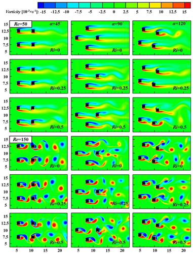
Considering the case of pure forced convection without the buoyancy effect (Ri = 0), when the rotation angle is α = 45° and α = 90°, respectively, the flow exhibits oscillatory modes and no vortex shedding occurs between the square cylinders at Re = 50. The vortex in the wake region appears as two symmetric narrow vortices, which are approximately parallel to the centerline along the flow direction. With increasing Reynolds number, the intensity of the flow oscillation is augmented correspondingly and leads to occurrence of vortex shedding. In the case of the rotation angle 45, a vortex street is generated due to the separated shear layers from both upstream (cylinder 1 and cylinder 3) and downstream square cylinders (cylinder 2 and cylinder 4). The space gap between the square cylinders is not enough to generate the co-shedding phenomenon which means that a new vortex street is formed by vortex merging from upstream and downstream vortices due to the interactions within the vortex street, and the vortex shedding is symmetric for pure forced convection. However, when the rotation angle is 90, the space gap between square cylinder 1 and square cylinder 4 is larger than the critical gap, and it will result in intensive interactions of the vortex street from the upstream square cylinder (cylinder 1) to the downstream square cylinder (cylinder 4). Besides, combined with the effect of the shear layer separated from cylinder 4, a new vortex street behind the downstream cylinder is generated due to the occurrence of amalgamative vortices, and this leads to an asymmetry of the vortex shedding. In the case of the rotation angle 120, it can be observed that the instantaneous vorticity contours are asymmetric for various Reynolds numbers due to the anomalous arrangement of the four square cylinders. The vortex behind cylinder 2 (cylinder 1) affects the vortex behind cylinder 4 (cylinder 3), and the interactions will increase as the Reynolds number is increased. The reason is that the intensity of the vortex shedding is enhanced at higher inlet velocity due to the higher inertia effect, and the vortices generated by the upstream square cylinders act on the surface of the downstream square cylinders and lead to formation of irregular vortex shedding.
Considering the case of mixed convection with buoyancy effect (Ri = 0.25 and Ri = 0.5), it can be observed that the symmetry of the vortex structure in the wake region is broken for all rotation angles and Reynolds numbers, and the flow field also becomes unstable and complicated due to the introduction of thermal buoyancy. At lower Reynolds number Re = 50, the vortex shedding phenomena behind the downstream cylinders can emerge, and the intensity of the vortex shedding increases as the Richardson number is increased. This phenomenon indicates that the additional thermal instability affected by the thermal buoyancy promotes the generation of vortices and exacerbates the interactions of vortices for the square cylinders. The literature also refers to this observation that compared with the spacing gap without regard to buoyancy, the presence of the thermal buoyancy causes the gap of the vortex shedding phenomenon to decrease due to the additional instability [Citation13]. This further confirms that the vortices can be formed for a fixed gap at a relatively lower Reynolds number. The vortex shedding of asymmetric structures (α = 120°) is more obvious and complex than that of symmetric structures (α = 45° and α = 90°). The reason is that the asymmetry of the arrangement of the four square cylinders reduces the spacing between the upstream and downstream cylinders along the flow direction so that the vortex generated by the upstream cylinders indirectly acts on the surface of the downstream cylinders, and the effect of the additional thermal buoyancy further enhances the vortex shedding strength. At a higher Reynolds number Re = 150, the vortex street behind the downstream square cylinders becomes more irregular as the Richardson number increases, and the separated shear layers interact outside the downstream square cylinders and further generate a complex vortex street structure. Hence, the flow pattern is much more sensitive and strongly affected by the thermal buoyancy.
4.1.2. Time evolution of lift coefficient
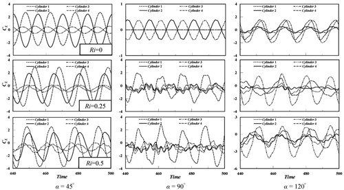
shows the time evolution of the lift coefficient for various rotation angles and Richardson numbers at Re = 100. The vortex shedding phenomena exist behind square cylinders at a higher Reynolds number. The time evolution of the lift coefficient also indicates the oscillation existence of the vortex shedding. In the case of the rotation angle 45, the behavior of the periodic oscillation of the lift coefficient of the four square cylinders with time can be observed at various Richardson numbers. The amplitude of oscillation for the four square cylinders is discriminating, and the amplitude of the upstream square cylinders (cylinder 1 and cylinder 3) is distinctly lower than that of the downstream square cylinders (cylinder 2 and cylinder 4) due to the restrictions and interactions of the downstream cylinder on the upstream vortex shedding. The trace of the periodic oscillation is relatively smooth and regular for the pure forced convection (Ri = 0), and the value of the lift coefficient oscillates around zero. This is mainly because the absence of a force term leads to symmetry of the flow structure with respect to the centerline. As thermal buoyancy is increased, the fluctuation trend gradually changes and the average value of the lift coefficient for the four square cylinders is less than zero. It can be concluded that the amplitude of the fluctuations for the upstream square cylinders is proportional to the Richardson number because the strength of the negative vortex grows up as the thermal buoyancy increases, forcing the four square cylinders to suffer a downward lift. Moreover, the track of the upstream lift coefficient becomes irregular and rough due to the interactions between the square cylinders and the downward lift. When the rotation angle is α = 90°, the time evolution of the lift coefficient for pure forced convection is still a periodic oscillation, and it is similar in the case of the rotation angle 45. However, the time evolution of the lift coefficient for the rotation angle 120 becomes disordered and nonsystematic at Ri = 0 due to the interactions between the vortices affected by the arrangement. In the existence of thermal buoyancy, it is found that the curves of the lift coefficient for the rotation angles (α = 90° and α = 120°) are anomalous and the amplitude of the oscillation is increased as the thermal buoyancy is increased. The downward lift and the higher inlet velocity cause the irregular vortex shedding and further lead to the irregular lift coefficient distribution.
Figure 5. Time evolution of lift coefficient for four heated square cylinder at Re = 100 for different rotation angles.
4.1.3. Drag and lift coefficients
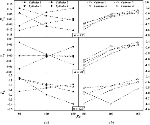
The variations of time-averaged lift and drag coefficients versus the Richardson numbers (Ri = 0, 0.25, 0.5) at Reynolds numbers (Re = 50, 150) are shown in . In the absence of thermal buoyancy, the values of the time-averaged lift coefficient for various Richardson numbers always exist around the zero value. These values for the symmetric structures (α = 45° and α = 90°) are opposite to each other except at a higher Reynolds number at α = 90° because the gap between square cylinder 1 and cylinder 4 is larger than the critical gap, and the strength of the vortex shedding further increases leading to interactions within the vortex street, and then irregular lift coefficients are formed. When the Richardson number is not equal to zero, shows that the value of the time-averaged lift coefficient for different Reynolds numbers and rotation angles is less than zero. The reason is that the square cylinders suffer a negative lift due to the effect of the imposed thermal buoyancy. The time-averaged lift coefficient for the various arrangements of the square cylinders increases as the Reynolds number increases and decreases as the Richardson number increases. This is because the intensity of the downward lift becomes stronger with increasing thermal buoyancy. According to the above observation, the arrangement of the four square cylinders under the influence of thermal buoyancy changes the flow pattern and further affects the variation of the lift coefficient. The time-averaged lift coefficient of the four square cylinders is extremely sensitive and disordered as the Reynolds number and Richardson number are varied.
Figure 6. Variation curves of time-averaged lift coefficient and drag coefficient of four square cylinders at Re = 50, 150 for various rotation angles and Richardson numbers.
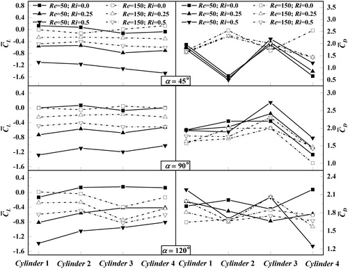
Figure 7. Variation curves of time-averaged lift coefficient for various rotation angles and Reynolds numbers at (a) Ri = 0 and (b) Ri = 0.5.
As a significant flow parameter, the time-averaged drag coefficient for the flow past the four square cylinders is depicted in the right part of . When the rotation angle is α = 45°, the drag coefficients of the upstream cylinders (cylinder 1 and cylinder 3) are always higher than those of the downstream cylinders (cylinder 2 and cylinder 4) at lower Reynolds number for all Richardson numbers. As the Reynolds number increases, the variation trend is destroyed and the drag coefficients of the downstream cylinders are increased. The increasing inlet velocity produces a stronger vortex shedding of the upstream cylinders and further enhances the force of the downstream ones. When the rotation angle is α = 90° and α = 120°, respectively, the variation of the time-averaged drag coefficient as a whole shows a downward trend with increasing Reynolds number, and it is chaotic for the four square cylinders at different Richardson numbers. Moreover, for all the Richardson numbers and rotation angles, the variation of the drag coefficient for the downstream cylinders is more sensitive than the trend of the upstream cylinders. This is due to stronger interactions and thermal buoyancy. However, the effect of the Richardson number and the arrangement on the drag is weaker than that on the lift according to the above observation.
4.2. Heat transfer characteristics
4.2.1. Isotherms pattern
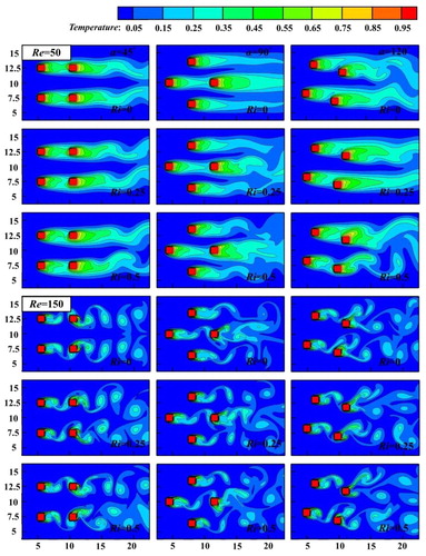
To further investigate the effects of the thermal buoyancy on the temperature field near the square cylinders domain, the isotherms contours for various rotation angles at Re = 50 and Re = 150 are shown in . Overall, the temperature isotherms are densely concentrated on the front surfaces of the square cylinders, and we know that a strong temperature gradient around the square cylinders represents a significant heat exchange in these areas, and then it further indicates that the front face has the highest heat transfer rate. In contrast, the rear surfaces of the four square cylinders have a relatively sparse and smaller induced temperature gradient, indicating a relatively lower heat transfer rate. At the lower Reynolds number Re = 50, the thermal boundary layer is approaching the surfaces of the four square cylinders. As the Reynolds number increases, the isotherm contours have a dramatic variation and the vortices are generated behind the square cylinders to enhance the heat transfer. It is observed that energy can be transported by the fluid flow to the downstream square cylinders. The temperature distribution in the case of pure convective flow is analyzed first. The symmetry of the isotherm contours with respect to the centerlines can be observed for the rotation angles α = 45° and α = 90° at lower Reynolds number Re = 50, and the symmetric feature will be broken as the inlet velocity increases at α = 90°. Meanwhile, the isotherm contours at α = 120° are also asymmetric for varying Reynolds number. The trend is similar to the tendency of the instantaneous vorticity contours. By the addition of thermal buoyancy, the thermal field becomes unstable and complex. It can be observed that the downstream cylinder has an upward drift in the wake region. The reason is that the thermal buoyancy forces the fluid up from the bottom half of the wake to the top half [Citation13]. According to the mass conservation law, a lot of fluid needs to be transported, and this results in the plume-like structure produced behind the downstream cylinders and will be obvious at a higher Reynolds number.
Figure 8. Isotherm contours for flow past four heated square cylinders in different rotation angle arrangements for various Richardson numbers at Re = 50, 150.
4.2.2. The global time-averaged Nusselt
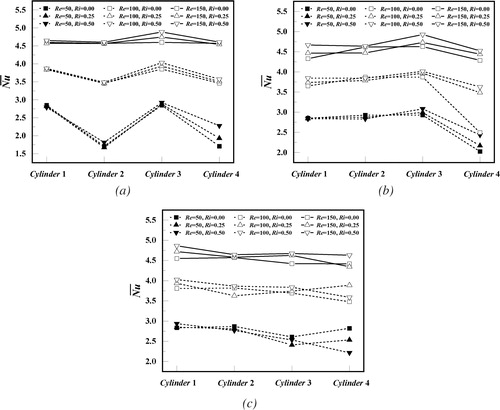
To investigate the effects of the thermal buoyancy and the arrangement on the heat transfer characteristics, meticulously present the global time-averaged Nusselt numbers of the four square cylinders for varying Richardson number and rotation angle at various Reynolds numbers. From a macroscopic perspective, the global time-averaged Nusselt number is proportional to the Reynolds and Richardson numbers in the case of the symmetrical structures (α = 45° and α = 90°), and it increases sharply with increasing Reynolds number, although it rises slowly in the Richardson number range from 0 to 0.5. This is because a higher Reynolds number produces a higher temperature gradient, which further results in enhanced heat transfer rate on the surfaces of the square cylinders. When the rotation angle is α = 45°, it is worthwhile to note that the time-averaged Nusselt numbers of the upstream cylinders (cylinder 1 and cylinder 3) are relatively higher than those of the downstream cylinders (cylinder 2 and cylinder 4), and the trend of the gap between the upstream and downstream Nusselt numbers become weak as the Reynolds number increases. The reason is that the undisturbed fluid flows through the upstream square cylinders, providing a higher heat transfer rate than that of the downstream square cylinders. For the rotation angle α = 90°, the heat transfer rate of square cylinder 4 is obviously lower than that of the other three cylinders at varying Richardson number and Reynolds number, and the trend of the time-averaged Nusselt number of the square cylinder 1 is actually closer to the variation of a single square cylinder. The reason is that the gap between the square cylinder 1 and square cylinder 4 is more than 5 D, which leads to a weak effect of cylinder 4 on the square cylinder 1 in the case of the vortex shedding. In addition, the heat transfer rate of the square cylinder 2 is approaching that of cylinder 3 in the absence of thermal buoyancy, while the heat transfer rate of cylinder 3 is relatively higher than that of cylinder 2 with the addition of thermal buoyancy. This is attributed to the fact that a negative lift leads to an increased heat transfer rate of the square cylinder 3. When the rotation angle is α = 120°, the time-averaged Nusselt number has a rapidly rising trend as the inlet velocity grows up, and it has a slower growth trend with Ri at higher Reynolds number, while this trend becomes abnormal at lower Reynolds number. This is mainly due to the effect of the arrangement for four square cylinders on the vortex shedding and thermal field. In any case, the increase of Reynolds numbers and the addition of thermal buoyancy enhance the heat transfer rate for the four square cylinders.
Figure 9. The global time-averaged Nusselt number over the surface of the square cylinders for various Reynolds numbers and Richardson numbers: (a) α = 45°; (b) α = 45°; (c) α = 120°.
4.2.3. Local Nusselt number
plot the distributions of the local Nusselt number along the surfaces of the four square cylinders at different Richardson numbers and rotation angles with Re = 100. From a macro perspective, the distribution of the local Nusselt number for varying rotation angle and Richardson number has a common tendency. The local Nusselt number on the front face (A-B) is highest among all faces of the square cylinder, which indicates the largest heat transfer rate appear at the front face. Moreover, the local Nusselt number increases from the midpoint of the front face (A-B) to the edge points (A and B). This is because the fluid from the front face of the square cylinder flows through the top and bottom surfaces to the rear, and the heat flux in the upstream is advected downstream along the direction of the fluid flow, which further results in the highest heat transfer rate of the front surface among all surfaces. When the fluid flows past and through the upper (A-D) and lower (B-C) faces of the square cylinder, the local Nusselt number has a sharp declining trend. Until the fluid flows through points C and D to the trailing edge surface, the Nusselt number reaches a relatively low tendency compared to the other three surfaces, which is due to the wake formation behind the square cylinder.
Figure 10. Local Nusselt number distribution on four square cylinders at Re = 100 for α = 45°: (a) Ri = 0; (b) Ri = 0.25; (c) Ri = 0.5.
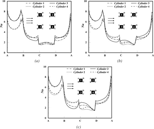
Figure 11. Local Nusselt number distribution on four square cylinders at Re = 100 for α = 90°: (a) Ri = 0; (b) Ri = 0.25; (c) Ri = 0.5.
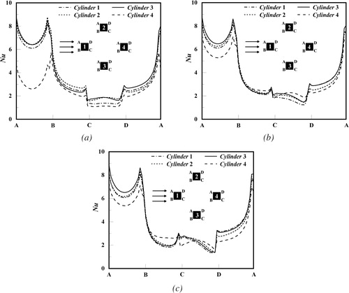
Figure 12. Local Nusselt number distribution on four square cylinders at Re = 100 for α = 120°: (a) Ri = 0; (b) Ri = 0.25; (c) Ri = 0.5.

In the case of the rotation angles α = 45° and α = 90°, it is found that the distribution of the local Nusselt number shows a symmetric trend with respect to the centerline of the square cylinder along the flow direction in the absence of thermal buoyancy, which is due to the symmetry structure. However, the symmetry characteristics of the distribution of the local Nusselt number at α = 120° gradually becomes weak. To a certain extent, this indicates that the arrangement of the square cylinders affects the variation of the heat transfer rate of the cylinder surfaces due to the disturbance of the flow arrangement. With the addition of the thermal buoyancy, the distribution of the local Nusselt number has changed significantly and the original symmetry is broken. For the rotation angle α = 45°, the gap of the Nusselt number on the surface of the four square cylinders gradually increases as the Richardson number is inceased, and the variation of Nusselt number of the rear surface (C-D) is most pronounced compared to the other three faces of the square cylinder, which is because the imposed thermal buoyancy leads to irregular vortex shedding behind the rear face. When the rotation angle is α = 90°, it can be observed that the Nusselt number of the front surface of the square cylinder 4 grows up sharply with the increase of the Richardson number. At Re = 100, the strength of the vortex shedding from the square cylinder 1 increases with the addition of thermal buoyancy and further acts on the front surface of the square cylinder 4, and then leads to enhancement of the heat transfer rate of the front face of cylinder 4. Besides, the rear surfaces of the four square cylinders also undergo dramatic variations, which is similar to the case of the rotation angle 45. When the rotation angle is α = 120°, the differences of the distribution of the local Nusselt number on the surfaces for the four square cylinders have changed dramatically as the Richardson number is not equal to zero, especially for the square cylinder 3 and cylinder 4. This is mainly because the addition of the thermal buoyancy causes the vortex shedding produced by the square cylinder 2 (cylinder 1) to increase the interactions of the square cylinder 4 (cylinder 3), which in turn affects the heat transfer rate of the square cylinder 4 (cylinder 3) to change drastically. In brief, thermal buoyancy has a significant influence on the distribution of the local Nusselt number.
5. Conclusions
In the present study, the thermal buoyancy and the arrangement of four square cylinders are strongly regarded as two key factors. The hydrodynamic and thermal transport characteristics of a buoyancy-driven cross flow through four heated square cylinders with various rotation angles (α = 45°, 90°, 120°) are investigated in detail. The lattice Boltzmann method with a multiple relaxation time collision operator for the velocity field and a single relaxation time collision operator for the temperature field is used as the primary tool to simulate the phenomena. Furthermore, the four heated square cylinders are placed in an adiabatic horizontal channel, and a uniform velocity is applied at the inlet. Accordingly, the simulations are carried out at Re = 50–150 for Ri = 0–0.5. Several significant conclusions are found as follows:
The asymmetrical arrangement of four square cylinders (α = 120°) for pure forced convection shows an irregular and instable flow and thermal patterns compared to the symmetrical structures (α = 45° and α = 90°). This feature is prominent at higher Reynolds numbers since the vortex shedding pattern generated by the upstream square cylinder is destroyed by the irregular structure.
With the addition of the thermal buoyancy, the flow and thermal patterns for all arrangements become disordered and nonsystematic. The thermal pattern for the downstream cylinders has an upward drift in the wake region, and a plume-like structure is formed behind the downstream cylinders in the buoyancy-driven cross flow.
The drag and lift coefficients are relatively sensitive to the Reynolds number and Richardson number, and they have different variation trends for each square cylinder at different rotation angles. The value of the lift coefficient for each cylinder is always less than zero due to a negative lift suffered when the Richardson number is not zero.
The global time-averaged Nusselt number is increased as the Reynolds number increases and makes the highest heat transfer rate at higher Reynolds number due to the larger temperature gradient. With increasing Richardson number, the heat transfer rate gradually is enhanced due to the addition of thermal buoyancy. The variation tendency of the time-averaged Nusselt number for the asymmetrical arrangement of four square cylinders is discriminating and erratic compared to the symmetrical structures.
The local Nusselt number on the front face of the square cylinder reaches the maximum among four surfaces of the square cylinder due to a strong temperature gradient concentrated on the front surface. The rear face of the square cylinder performs the lowest values of the local Nusselt number on the other hand. The distribution of the local Nusselt number on the front and rear surfaces for all rotation angles is intensively affected by the thermal buoyancy.
| Nomenclature | ||
| c | = | lattice velocity |
| cs | = | speed of sound (m·s−1) |
| CD | = | drag coefficient |
| CL | = | lift coefficient |
| D | = | length of the square cylinder |
| ei | = | discrete velocity in direction i |
| Fr | = | total resultant force (N) |
| FD | = | drag force (N) |
| FL | = | lift force (N) |
| fi | = | density distribution function in direction i |
| fieq | = | equilibrium distribution function of density in direction i |
| Fi | = | force term (N) |
| g | = | gravitational acceleration |
| gi | = | temperature distribution function in direction i |
| gieq | = | equilibrium distribution function of temperature in direction i |
| Gr | = | Grashof number |
| H | = | height of the computational domain |
| Lu | = | upstream length |
| Ld | = | downstream length |
| N | = | number of lattices on the cylinder |
| Nu | = | local Nusselt number, ∂θ/∂n |
| p | = | dimensionless pressure |
| Pr | = | Prandtl number, ν/α |
| Re | = | Reynolds number, u∞D/ν |
| Ri | = | Richardson number, gβ(TW-T∞)D3/νγ |
| xb | = | boundary node |
| T | = | dimensional temperature, (°C) |
| u | = | nondimensional x-component velocity (m·s−1) |
| v | = | nondimensional y-component velocity (m·s−1) |
| Greek symbols | = |
|
| α | = | rotation angle |
| β | = | thermal expansion coefficient |
| γ | = | thermal diffusivity, (m2·s−1) |
| θ | = | dimensionless temperature, (T − T∞)/(TW − T∞) |
| ν | = | kinematic viscosity, (m2·s−1) |
| ρ | = | fluid density (kg·m−3) |
| τf | = | dimensionless relaxation time for flow field |
| τg | = | dimensionless relaxation time for temperature field |
| ωi | = | weight coefficients in a direction i |
| Subscripts | = |
|
| ∞ | = | far-field value |
| i | = | lattice link direction |
| W | = | wall |
Additional information
Funding
References
- M. M. Alam, Y. Zhou, and X. W. Wang, “The wake of two side-by-side square cylinders,” J. Fluid Mech., vol. 669, pp. 432–471, 2011. DOI: 10.1017/S0022112010005288.
- M. Kapitz, C. Teigeler, R. Wagner, C. Helcig, and S. A. D. Wiesche, “Experimental study of the influence of the Prandtl number on the convective heat transfer from a square cylinder,” Int. J. Heat Mass Transf., vol. 120, pp. 471–480, 2018. DOI: 10.1016/j.ijheatmasstransfer.2017.12.032.
- A. Sohankar, M. Abbasi, M. M. Ahmadabadi, M. M. Alam, and F. Zafar, “Experimental study of the flow around two finite square cylinders,” Arch. Mech., vol. 70, pp. 457–480, 2018. DOI: 10.24423/aom.2965.
- R. Ali and N. Hasan, “Steady and unsteady flow regimes in two-dimensional mixed convective flow of air past a heated square cylinder,” Int. J. Mech. Sci., vol. 175, p. 105533, 2020. DOI: 10.1016/j.ijmecsci.2020.105533.
- D. Chatterjee and G. Biswas, “The effects of Reynolds and Prandtl numbers on flow and heat transfer across tandem square cylinders in the steady flow regime,” Numer. Heat Transf. A - Appl,. vol. 59, no. 6, pp. 421–437, 2011. DOI: 10.1080/10407782.2011.552374.
- M. A. Moussaoui, A. Mezrhab, and H. Naji, “A computation of flow and heat transfer past three heated cylinders in a vee shape by a double distribution MRT thermal lattice Boltzmann model,” Int. J. Therm. Sci., vol. 50, no. 8, pp. 1532–1542, 2011. DOI: 10.1016/j.ijthermalsci.2011.03.011.
- Y. Q. Zheng, G. N. Li, W. W. Guo, and C. Dong, “Lattice Boltzmann simulation to laminar pulsating flow past a circular cylinder with constant temperature,” Heat Mass Transf., vol. 53, no. 9, pp. 2975–2986, 2017. DOI: 10.1007/s00231-017-2043-2.
- A. Sanyal and A. Dhiman, “Wake interactions in a fluid flow past a pair of side-by-side square cylinders in presence of mixed convection,” Phys. Fluids, vol. 29, no. 10, p. 103602, 2017. DOI: 10.1063/1.5005118.
- A. Sanyal and A. Dhiman, “Effect of thermal buoyancy on a fluid flowing past a pair of side-by-side square bluff-bodies in a low-Reynolds number flow regime,” Phys. Fluids, vol. 30, no. 6, p. 063603, 2018. DOI: 10.1063/1.5025652.
- A. E. F. Monfared, A. Sarrafi, S. Jafari, and M. Schaffie, “Thermal flux simulations by lattice Boltzmann method; investigation of high Richardson number cross flows over tandem square cylinders,” Int. J. Heat Mass Transf., vol. 86, pp. 563–580, 2015. DOI: 10.1016/j.ijheatmasstransfer.2015.03.011.
- S. Biswas, P. Sharma, B. Mondal, and G. Biswas, “Analysis of mixed convective heat transfer in a ribbed channel using the lattice Boltzmann method,” Numer. Heat Transf. A – Appl., vol. 68, no. 1, pp. 75–98, 2015. DOI: 10.1080/10407782.2014.965095.
- D. Chatterjee and S. Amiroudine, “Two-dimensional mixed convection heat transfer from confined tandem square cylinders in cross-flow at low Reynolds numbers,” Int. Commun. Heat Mass Transf., vol. 37, no. 1, pp. 7–16, 2010. DOI: 10.1016/j.icheatmasstransfer.2009.10.007.
- D. Chatterjee and B. Mondal, “Mixed convection heat transfer from tandem square cylinders for various gap to size ratios,” Numer. Heat Transf. A – Appl., vol. 63, no. 2, pp. 101–119, 2013. DOI: 10.1080/10407782.2012.725007.
- R. N. Yuan, M. X. Wu, and Z. Huang, “Steady mixed convective flow and heat transfer from tandem square cylinders in a horizontal channel,” Numer. Heat Transf. A – Appl., vol. 71, no. 10, pp. 1023–1033, 2017. DOI: 10.1080/10407782.2017.1330921.
- K. Lam and S. C. Lo, “A visualization study of cross-flow around four cylinders in a square configuration,” J. Fluids Struct., vol. 6, no. 1, pp. 109–131, 1992. DOI: 10.1016/0889-9746(92)90058-B.
- K. Lam and X. Fang, “The effect of interference of four equispaced cylinders in cross flow on pressure and force coefficients,” J. Fluids Struct., vol. 9, no. 2, pp. 195–214, 1995. DOI: 10.1006/jfls.1995.1010.
- K. Lam, J. Y. Li, K. T. Chan, and R. M. C. So, “Flow pattern and velocity field distribution of cross-flow around four cylinders in a square configuration at a low Reynolds number,” J. Fluids Struct., vol. 17, no. 5, pp. 665–679, 2003. DOI: 10.1016/S0889-9746(03)00005-7.
- K. Lam, J. Y. Li, and R. M. C. So, “Force coefficients and Strouhal numbers of four cylinders in cross flow,” J. Fluids Struct., vol. 18, no. 3–4, pp. 305–324, 2003. DOI: 10.1016/j.jfluidstructs.2003.07.008.
- M. Y. Liu, L. F. Xiao, and L. J. Yang, “Experimental investigation of flow characteristics around flow square-cylinder arrays at subcritical Reynolds numbers,” Int. J. Nav. Archit. Ocean Eng., vol. 7, no. 5, pp. 906–919, 2015. DOI: 10.1515/ijnaoe-2015-0063.
- E. H. Wang, W. H. Xu, Y. Yu, L. D. Zhou, and A. Incecik, “Flow-induced vibrations of three and four long flexible cylinders in tandem arrangement: An experimental study,” Ocean Eng., vol. 178, pp. 170–184, 2019. DOI: 10.1016/j.oceaneng.2019.02.053.
- W. H. Xu, S. H. Zhang, B. Liu, E. H. Wang, and Y. Bai, “An experimental study on flow-induced vibration of three and four side-by-side long flexile cylinders,” Ocean Eng., vol. 169, pp. 492–510, 2018. DOI: 10.1016/j.oceaneng.2018.09.038.
- W. S. Abbasi, U.-I. Shams, S. C. Saha, Y. T. Gu, and Z. C. Ying, “Effect of Reynolds numbers on flow past four square cylinders in an in-line square configuration for different gap spacings,” J. Mech. Sci. Technol., vol. 28, pp. 539–552, 2014. DOI: 10.1007/s12206-013-1121-8.
- Y. Y. Gao, K. Yang, B. F. Zhang, K. Y. Cheng, and X. P. Chen, “Numerical investigation on vortex-induced vibrations of four circular cylinders in a square configuration,” Ocean Eng., vol. 175, pp. 223–240, 2019. DOI: 10.1016/j.oceaneng.2019.02.012.
- Y. Kahil, S. Benhamadouche, A. S. Berrouk, and I. Afgan, “Simulation of subcritical-Reynolds -number flow around four cylinders in square arrangement configuration using LES,” Eur. J. Mech. B - Fluids, vol. 74, pp. 111–122, 2019. DOI: 10.1016/j.euromechflu.2018.11.008.
- J. A. Esfahani and A. V. B. Hagh, “LB simulation of heat transfer in flow past a square unit of four isothermal cylinders,” C. R. Mec., vol. 340, no. 7, pp. 526–535, 2012. DOI: 10.1016/j.crme.2012.03.011.
- Y. H. Qian, D. D’Humières, and P. Lallemand, “Lattice BGK models for Navier-Stokes equation,” Europhys. Lett., vol. 17, no. 6, pp. 479–484, 1992. DOI: 10.1209/0295-5075/17/6/001.
- P. J. Dellar, “Incompressible limits of lattice Boltzmann equations using multiple relaxation times,” J. Comput. Phys., vol. 190, no. 2, pp. 351–370, 2003. DOI: 10.1016/S0021-9991(03)00279-1.
- Q. S. Zou and X. Y. He, “On pressure and velocity boundary conditions for the lattice Boltzmann BGK model,” Phys. Fluids, vol. 9, no. 6, pp. 1591–1598, 1997. DOI: 10.1063/1.869307.
- A. A. Mohamad, Lattice Boltzmann Method: Fundamentals and Engineering Applications with Computer Codes. Springer, New York, 2011.
- R. W. Mei, D. Z. Yu, W. Shyy, and L. S. Luo, “Force evaluation in the lattice Boltzmann method involving curved geometry,” Phys. Rev. E, vol. 65, no. 4, p. 041023, 2002. DOI: 10.1103/PhysRevE.65.041203.
- H. B. Li, X. Y. Lu, H. P. Fang, and Y. H. Qian, “Force evaluations in lattice Boltzmann simulations with moving boundaries in two dimensions,” Phys. Rev. E, vol. 70, p. 026701, 2002. DOI: 10.1103/PhysRevE.70.026701.