Abstract
Graphene-TiO2 was obtained by reduction of graphite oxide by the hydrothermal method. Using photocatalytic activity to reduce carbon dioxide to methanol and formic acid was investigated in this study. The results show that the graphene loading affects the absorption of light in the visible light region. A larger surface area can also improve the catalytic activity. The largest yield of methanol and formic acid, under light of 365 nm, can reach 160 and 150 μmol g−1, respectively, with 8.5% graphene loading. An increase in graphene loading can enhance photocatalytic performance, but too much will also decrease the reduction efficiency by shielding the light from reaching the catalytic surface. The effect of pH was also investigated. The mechanism of the reaction was also discussed in this study.
Implications:
Graphene-TiO2 hybrids were prepared by the hydrothermal method. Surface area and visible light adsorption increased with the graphene loading. Increased graphene loading improved the methanol and formic acid production. Too much graphene loading will decrease the reduction efficiency. The effect of pH shows that the HCO3− species prefers the formation of formic acid. The mechanism of the reaction was also discussed in this study.
Introduction
Society’s current use of fossil and nuclear fuels has many adverse consequences. One of those problems is global climate change caused by emissions of greenhouse gases from fossil fuel combustion. The surface temperature of the earth is maintained at an equilibrium level by receiving energy from the sun, balancing the outgoing infrared energy from the surface back into the space. If the earth had no atmosphere, the surface temperature of the earth would be −18 °C. This natural “greenhouse effect” maintains the surface at a temperature suitable for life, around 15 °C (Godfrey, Citation2004). Since the industrial revolution, however, human activities have been adding extra greenhouse gases to the atmosphere. The principle contributor to these increased emissions is carbon dioxide from the combustion of fossil fuels.
Scientists estimate that these human-induced emissions have caused a rise in the earth’s global mean surface temperature of 0.6 °C (Intergovernmental Panel on Climate Change [IPCC], Citation2001) during the 20th century. For the half million years before the 20th century, atmospheric concentration of CO2 has varied between 200 and 300 ppm by volume (Godfrey, Citation2004). However, it reached 370 ppm by 2001, and 399.55 ppm by January 2013 (National Oceanic and Atmospheric Administration National Climatic Data Center [NOAA-NCDC], 2013).
Several methods for capturing and storing CO2 released into the atmosphere due to human activity have been investigated over the years. This kind of technology, carbon capture and storage (CCS), involves collecting and generating a highly concentrated steam of almost pure CO2. CCS is used in a range of technologies and techniques that can capture up to 90% of future CO2 emissions from power stations and industrial sites (Richter et al., Citation2013).
Captured pure CO2 may be turned into energy rather than merely being stored at the bottom of the earth and ocean. In 1979, the photoreduction of CO2 to formaldehyde and methanol in purified water using the semiconductors TiO2, ZnO, CdS, GaP, SiC, and WO3 was reported (Inoue et al., Citation1979). The key to this method is to find sustainable and economical catalysts to convert CO2 to fuels.
Graphene is a very attractive material for its unique electronic properties, high transparency, flexible structure, and large theoretical specific surface area (Štengl et al., Citation2011; Y. Zhang et al., Citation2011; Jiang et al., Citation2011). One of its many applications is the use of graphene in the preparation of highly photoactive composite materials based on titanium oxides. Graphene is an ideal nanostructure product for pairing with titanium dioxide, increasing its photocatalytic activity (Štengl et al., Citation2011; Y. Zhang et al., Citation2011). As graphene is a metal-like conductor (Guo and Dong, Citation2011), the electrons freed after the titanium dioxide activation are easily transported to the graphene nanosheets and recombination of e− and h+ is strongly reduced, which increases the process yield (Štengl et al., Citation2011; Y. Zhang et al., Citation2011).
In this study, we will use graphene-loaded TiO2 to catalyze carbon dioxide reduction. This type of catalysts is usually used to oxidize organic pollutants, but their reduction efficiency has scarcely been studied. The effects of graphene loading and pH of the solution are also discussed in this study. The feasibility of energy generation by graphene-TiO2 (GN-TiO2) is revealed in this paper.
Experimental Methods
Preparation of graphite oxide
Graphite oxide (GO) was synthesized by the modified Hummer’s method. The graphite powders were first oxidized by mixing with NaNO3 and H2SO4. During this step, KMnO4 was added slowly, and the vessel was immersed in ice bath to keep the temperature under 5 °C. Then, the reaction was allowed to go on for 30 min under 35 °C. Finally, the reaction temperature was increased to 95 °C, and the reaction was maintained for 30 min. After reaction, 25 mL H2O2 was added and the GO obtained was washed with 1 mol L−1 HCl and deionized water.
Preparation of GN-TiO2
Graphite oxide was mixed with commercial TiO2 after ultrasonication for 1 hr. Then, the mixed solution was charged into a Teflon-lined autoclave. The autoclave was then oven-heated at 120 °C for 3 hr. The final products were obtained by filtration and washing, with subsequent drying at 100 °C overnight.
Characterization of GN-TiO2
A ultraviolet (UV) spectrometer (Hitachi, U-3900), scanned from 200 to 800 nm in wavelength, was used to collect the reflectance spectra of graphene-loaded TiO2 samples. High-resolution transmission electron microscopy (HR-TEM; JEOL, JEM-2000 FXΠ) was used for morphological observations of the catalysts. The crystal phase of the catalysts was tested by X-ray diffraction (XRD; X’Pert PRO) using Cu K radiation (λ = 0.1541 nm). And the elemental analyzer (EA; Elementar, Vario MICRO Cube) was used to analyze the percentage of graphene loading. Infrared spectroscopy (FTIR; NiCoLET-iS10) was performed to estimate the functional groups. The surface area of samples was determined from nitrogen adsorption-desorption isotherms at liquid nitrogen temperature using Brunauer-Emmett-Teller methods (Micromeritics, BET ASAP 2020N).
Photoreduction
Photocatalytic reduction was carried out using a double-wall cylindrical quartz reactor. This reactor was water-jacketed to maintain the solution temperature at 25 °C. Then, 2 mg L−1 of the photocatalyst was loaded into a 1 mol/L NaOH solution and stirred vigorously to form a suspension. After purging CO2 for 30 min, the solution was irradiated by a 150-W visible lamp. The methanol yield was determined by gas chromatograph (HP, G1800A) with fused silica capillary column (60 m × 0.25 mm × 0.25 μm). The detector was a mass detector and the carrier gas was He.
Results and Discussion
Characteristics of the materials
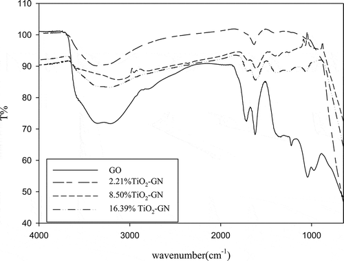
FTIR spectra are shown in . The peak at 1617.5 cm−1 in GO is attributed to the C=C bond. The adsorption bands at 1726.6, 1250, and 1045 cm−1 are attributed to the COOH, O–C–O, and O—C groups, respectively (Y. Zhang et al., Citation2011; Guo and Dong, Citation2011). The adsorption bands that appear between 3000 and 3500 cm−1 indicate the surface absorbed water and OH groups in water (Štengl et al., Citation2011; Y. Zhang et al., Citation2011; Guo and Dong, Citation2011). The peak around 1600 cm−1 is contributed by the skeletal vibration of grapheme (Y. Zhang et al., Citation2011; Fan et al., Citation2011; H. Zhang et al., Citation2010). The broad band under 1000 cm−1, in 2.21%, 8.50%, and 16.39% GN-TiO2, is attributed to the vibration of Ti–O–Ti bond in TiO2 (Y. Zhang et al., Citation2011; Guo et al., Citation2011; H. Zhang et al., Citation2010).
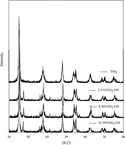
The crystal phases of the P25 and P25/graphene were measured by X-ray diffraction. The results in show that all the materials exhibit similar XRD patterns, and obvious graphene diffraction peaks were observed in different graphene loading.
The obvious peak at 27.4° can be corresponding to the rutile phase of TiO2, which can’t be observed in commercial TiO2. The XRD results demonstrate that anatase TiO2 was exclusively obtained regardless the percentage of graphene loading. The peak around 36°, attributed to rutile TiO2, shows that the crystal phase of TiO2 was changed by reaction with graphene during hydrothermal process (Deng et al., Citation2010). The peak around 43° that appear in graphene-loaded TiO2 is the crystal plane (111) of rutile, which also can’t be observed in commercial TiO2 (Xiao et al., Citation2008). The major crystal phase of TiO2 is rutile, the useful crystal phase both for adsorption and reaction. The research of Fujishima et al. showed that CO2 adsorption mainly existed on the TiO2 (110) single crystals, which was attributed to the rutile phase (Fujishima et al., Citation2000). Indrakanti et al. also confirmed the result of Fujishima et al. and proved that the anatase phase of TiO2 could not lead to charge transfer and form CO2⊸ (Indrakanti et al., Citation2009). The small change of the crystal may have been resulted from the formation of the C–O–Ti bonds.
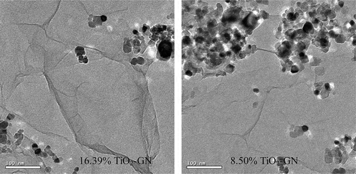
The transmission electron microscopy (TEM) images of GN-TiO2 are shown in . The images clearly illustrate the flake-like shape of graphene with wrinkles (Y. Zhang et al., Citation2011; Chen et al., Citation2010; Wang et al., Citation2008; H. Zhang et al., Citation2010). On the other hands, the TiO2 nanoparticles can also be observed. The figure shows that the 16.39% GN-TiO2 sheets are almost decorated by the TiO2 nanoparticals, compared with the 8.50% GN-TiO2 loading.
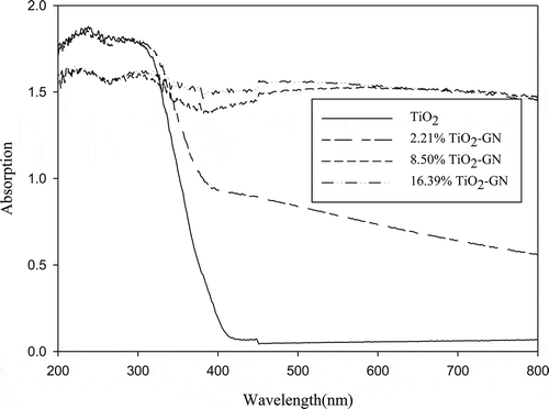
shows the ultraviolet-visible (UV-Vis) absorption spectra of pure TiO2 and GN-TiO2 composite. It is obvious that GN-TiO2 not only has a red shift, but also has a stronger absorption in the visible light region. This enhanced light absorption can be explained by the formation of chemical bonding between TiO2 and graphene (Štengl et al., Citation2011; C. Zhao et al., Citation2012). In the heat treatment reaction, the functional groups on the surface of GO (–COOH, –OH, and so on) disappeared. The π electron of the carbon atom can’t entirely bond with others to form the π bonds, so some unpaired π electrons bond with the free electrons on the TiO2 surface to form C–O–Ti bonds (Zhang and Pan, Citation2011). The C–O–Ti bonds favor charge transfer upon light excitation (Guo et al., Citation2011; H. Zhang et al., Citation2010).
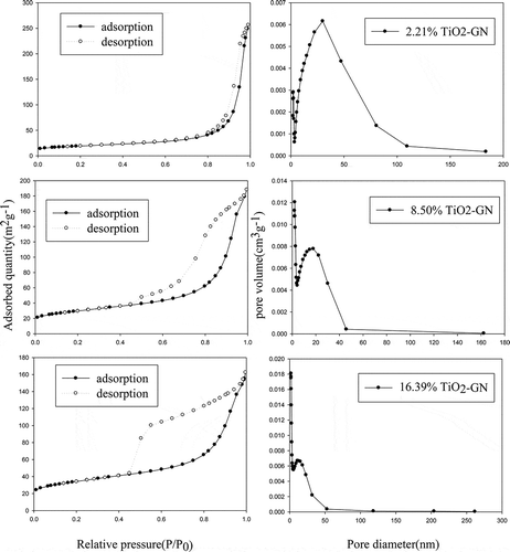
The specific surface area and total pore volume of the prepared GN-TiO2 are listed in . The pore-size distribution plot and nitrogen adsorption-desorption isotherms are shown in . According to the results, the surface areas increased with an increase in graphene content. The average pore size lies between 8 and 25 nm. With decreasing graphene content, the pore size distribution of the GN-TiO2 narrows.
Table 1. Surface areas, pore volumes, and pore widths of various GN-TiO2 samples
The effect of the graphene loading
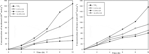
shows the dependence of methanol and formic acid yields on illumination time. Various yields of formic acid and methanol were obtained depending on the graphene loading. The formation efficiencies of formic acid and methanol were found to be higher for GN-TiO2 than TiO2. The activity of catalysts followed the order of 8.50% GN-TiO2 > 16.39% GN-TiO2 > 2.21% GN-TiO2 > TiO2. The largest yields of formic acid and methanol, under a light of 365 nm, were 167.79 and 155.78 μmol g−1, with 8.5% graphene loading. The results clearly indicate that the photo reduction performance of TiO2 greatly improves with the addition of graphene. The higher efficiency can be attributed to two factors. First, the conducting band of TiO2 is around 4.21 eV (Xu and Martin, Citation2000). Thus, the work function of graphene of ≈4.42 eV (Czerw et al., Citation2002) allows the charge transfer from TiO2 to graphene (Štengl et al., Citation2011). The excited-state electrons transporting from the TiO2 upon UV illumination into the graphene can be shuttled freely along the conducting network of the graphene, and subsequently transferred to the surface to react with CO2 (Tu et al., Citation2013). The longer lifetime and mean free path for electrons on graphene implies that energetic electrons will cover a larger area of the graphene surface, thereby increasing the likelihood of interaction with the adsorbed reactants. Another factor is the larger surface area of GN-TiO2. It offers more active adsorption sites and photocatalytic reaction centers (Tu et al., Citation2013). However, a further increase in the graphene content leads to a deterioration of photocatalytic performance, which is likely due to the increased scattering and absorbance of photons through excess graphene in the photocatalytic system, shielding the light from reaching the surface of the TiO2 photocatalysts (Tu et al., Citation2013). As a result, an appropriate graphene loading is important in optimizing the photocatalytic activity of the GN-TiO2 nanocomposites.
The effect of pH
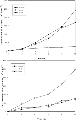
The effect of pH was also explored in this study. The results are shown in . The results show that the formation of methanol and formic acid are different at different pH levels because of the complications between carbonate species (Whipple et al., Citation2010). In view of the mass balance, the percentage of different species can be calculated by eqs 1 and 2:
We may conclude that H2CO3 is the dominant carbonate species at a pH of 6.3. The predominant species changes to HCO3− when the pH is between 6.3 and 10.3. CO32− will be the main species if the pH exceeds 10.3 (Chen et al., Citation2007). The percentage of different carbonate species under different pH can be calculated by eqs 3 and 4:
Thus, the concentration of H2CO3 and HCO3− may be expressed by CO32− (as shown in eqs 5 and 6).
The percentage of carbonate species can be expressed by [H+] (related to pH), as shown in eqs 7, 6, and 7:
The results show that the species of HCO3− accounts for 97.6% of the carbonate species at a pH of 8, and formic acid is the main product of the reaction (about 90% of all products). This means that the HCO3− species prefers the formation of formic acid. The formation of methanol is very low at a pH of 8. At all the pH levels in this study, the formation of methanol was lower than formic acid. This is because methanol cannot be formed directly and must be reduced stepwisely to HCOOH and HCHO first. The formation of methanol under alkaline condition was higher than under acid and neutral conditions. The result is similar to the findings of Liu and colleagues (Liu et al., Citation2009). This phenomenal was explained by that it was most likely of CO32− to adopt the photo-generated electrons and give rise to methanol after protonation (Liu et al., Citation2009).
The mechanism of the reaction
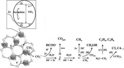
The mechanism of this reduction can be summarized as shown in . When a photon with an energy that matches or exceeds the bond gap energy of the semiconductor is incident on a semiconductor surface, a conductive band electron (e−) will jump to its valence band, leaving a positively charged hole behind (h+) (Chen et al., Citation2007; Lee et al., Citation2003). Because of a notable synergetic effect between TiO2 nanosheets and graphene, the composite cocatalyst has several advantages, including suppression of charge recombination, improvement of interfacial charge transfer, and increase in the number of active adsorption sites and photocatalytic reaction centers (Xiang et al., Citation2012a, Citation2012b). The photo-generated electron can be transferred to the surface of the graphene to inhibit recombination (Morel and Hering, Citation1993). The separated electron shows a strong reducing ability in the presence of H2O. Depending on the different electrons transferred, the CO2 can be reduced to generate HCHO, CO, HCOOH, CH3OH, CH4, and other hydrocarbons, as shown in eqs 10–21) (C. Zhao et al., Citation2012). The summaries of other authors show that the formation of CO2•− was the start of the reaction, as shown in eq 11 (Kohno et al., Citation1998; Liu et al., Citation1998; Subrahmanyam et al., Citation1999). The CO2•− can react with H+ to generate •CH3 and •CH3O, as shown in eqs 13– 15. These species can react with H+ and H2O to generate organic products.
Conclusion
Using the hydrothermal method, we succeed in making TiO2 and graphene hybrids. This synthesis process is simple and efficient. The photocatalytic activity of GN-TiO2 is superior to that of commercial TiO2 in the reaction of carbon dioxide reduction. The results of this study show that an increase in graphene loading can increase the surface area of the catalyst, but more is not necessarily better. Although a larger surface area affords more active adsorption sites and photocatalytic reaction centers, too much will prevent light from reaching the surface of the TiO2 photocatalysts. In this study, an 8.50% graphene loading displayed the best performance. The effect of pH was also discussed in the study. The results show that the HCO3− species prefer the formation of formic acid. The mechanism was also discussed in this study.
Additional information
Notes on contributors
Qian Zhang
Qian Zhang is a Ph.D. student and Cheng-Fang Lin is a professor in the Graduate Institute of Environmental Engineering, National Taiwan University, Taiwan, China.
Cheng-Fang Lin
Qian Zhang is a Ph.D. student and Cheng-Fang Lin is a professor in the Graduate Institute of Environmental Engineering, National Taiwan University, Taiwan, China.
You Hai Jing
You Hai Jing is a professor in the College of the Environment and Ecology, Xiamen University, Xiamen City, Province of Fujian, China.
Chang-Tang Chang
Chang-Tang Chang is a professor in the Department of Environmental Engineering, National I-Lan University, I-Lan City, Taiwan, China.
References
- Chen, C., W. Cai, M. Long, B. Zhou, Y. Wu, D. Wu, and Y. Feng. 2010. Synthesis of visible-light responsive graphene oxide/TiO2 composites with P/N heterojunction. ACS Nano. 4:6425–6432. doi:10.1021/nn102130m
- Chen, C.C., C.S. Lu, Y.C. Chung, and J.L. Jan. 2007. UV light induced photodegradation of malachite green on TiO2 nanoparticles. J. Hazard. Mater. 141:520–528. doi:10.1016/j.jhazmat.2006.07.011
- Czerw, R., B. Foley, D. Tekleab, A. Rubio, P.M. Ajayan, and D L. Carroll. 2002. Substrate-interface interactions between carbon nanotubes and the supporting substrate. Phys. Rev. B 66:408–414. doi:10.1103/PhysRevB.66.033408
- Deng, Q., M. Wei, Z. Hong, X. Ding, L. Jiang, and K. Wei. 2010. Selective synthesis of rutile, anatase, and brookite nanorods by a hydrothermal route. Current Nanoscience. 6:479–482. doi:10.2174/157341310797574970
- Fan, Y., H.T. Lu, J.H. Liu, C.P. Yang, Q.S. Jing, X. ZhangY, K. YangX, and K.J. Huang. 2011. Hydrothermal preparation and electrochemical sensing properties of TiO2-graphene nanocomposite. Colloids Surf. B Biointerfaces 83:78–82. doi:10.1016/j.colsurfb.2010.10.048
- Fujishima, A., T.N. Rao, and D.A. Tryk. 2000. Titanium dioxide photocatalysis. J. Photochem. Photobiol. C Photochem. Rev. 1:1–21. doi:10.1016%2FS1389-5567%2800%2900002-2
- Godfrey, B. 2004. Renewable Energy Power for a Sustainable Future. Oxford, UK: Oxford University Press.
- Guo, S., and S. Dong. 2011. Graphene nanosheet: Synthesis, molecular engineering, thin film, hybrids, and energy and analytical applications. Chem. Soc. Rev. 40:2644–2672. doi:10.1039/C0CS00079E
- Guo, J., S. Zhu, Z. Chen, Y. Li, Z. Yu, Q. Liu, J. Li, C. Feng, and D. Zhang. 2011. Sonochemical synthesis of TiO2 nanoparticals on graphene for use as photocatalyst. Ultrason. Sonochem. 18:1082–1090. doi:10.1016/j.ultsonch.2011.03.021
- Indrakanti, V.P., J.D. Kubicki,and H.H. Schobert. 2009. Photo induced activation of CO2 on Ti-based heterogeneous catalysts: Current state, chemical physics-based insights and outlook. Energy Environ. Sci. 2:745–758. doi:10.1039%2Fb822176f
- Inoue, T., A. Fujishima, S. Konishi, and K. Honda. 1979. Photo electrocatalytic reduction of carbon dioxide in aqueous suspensions of semiconductor powders. Nature 277:637–638. doi:10.1038/277637a0
- Intergovernmental Panel on Climate Change. 2001.
- Jiang, G, Z. Lin, C. Chen, L. Zhu, Q. Chang, N. Wang, W. Wei, and H. Tang. 2011. TiO2 nanoparticles assembled on graphene oxide nanosheets with high photocatalytic activity for removal of pollutants. Carbon 49:2693–2701. doi:10.1016/j.carbon.2011.02.059
- Kohno, Y., T. Tanaka, T. Funabiki, and S. Yoshida. 1998. Identification and reactivity of a surface intermediate in the photoreduction of CO2 with H2 over ZrO2. J. Chem. Soc. Faraday Trans. 94:1875–1880. doi:10.1039/A801055B
- Lee. J.M., M.S. Kim, B. Hwang,W. Bae, and B.W. Kim.2003. Photodegradation of acid red 114 dissolved using a photo-Fenton process with TiO2. Dyes Pigments 56:59–67. doi:10.1016%2FS0143-7208%2802%2900112-2
- Liu. BJ., T. Torimoto, and H. Yoneyama. 1998. Photocatalytic reduction of CO2 using surface-modified CdS photocatalysts in organic solvents. J. Photochem. Photobiol. A Chem. 113:93–97. doi:10.1016%2FS1010-6030%2897%2900318-3
- Liu. Y, B. Huang, Y. Dai, X. Zhang, M. Qin, X. Jiang, and M. Whangbo. 2009. Selective ethanol formation from photocatalytic reduction of carbon dioxide in water with BiVO4 photocatalyst. Catal. Commun. 11:210–213. doi:10.1016/j.catcom.2009.10.010
- Morel, F M M., and J.G. Hering. 1993. Principles and Applications of Aquatic Chemistry. New York: Wiley.
- National Oceanic and Atmospheric Administration National Climatic Data Center.
- Richter, R.K., T. Ming, and S. Caillol. 2013. Fighting global warming by photocatalytic reduction of CO2 using giant photocatalytic reactors. Renew. Sustain. Energy Rev. 19(C):69–96.
- Šteng lV, D. Popelková, and P. Vláčil. 2011. TiO2-graphene nanocomposite as high performace photocatalysts. J. Phys. Chem. C 115:25209–25218. doi:10.1021/jp207515z
- Subrahmanyam, M., S. Kaneco, and N. Alonso-Vante. 1999. A screening for the photo reduction of carbon dioxide supported on metal oxide catalysts for C1–C3 selectivity. Appl. Catal. B Environ. 23:169–174. doi:10.1016%2FS0926-3373%2899%2900079-X
- Tu, W., Y. Zhang, Q. Liu, S. Yan, S. Bao, X. Wang, M. Xiao, and Z. Zou. 2013. An in situ simultaneous reduction-hydrolysis technique for fabrication of TiO2—Graphene 2D sandwich-like hybrid nanosheets: Graphene-promoted selectivity of photocatalytic-driven hydrogenation and coupling of CO2 into methane and ethane. Adv. Funct. Mater. 23:1743–1749. doi:10.1002/adfm.201202349
- Wang, G., J. Yang, J. Park, X. Gou, B. Wang, H. Liu, and J. Yao. 2008. Facile synthesis and characterization of graphene nanosheets. J. Phys. Chem. C 112:8192–8195. doi:10.1021/jp710931h
- Whipple, D T., Finke, E C., and Kenis, P J A. 2010. Micro fluidic reactor for the electrochemical reduction of carbon dioxide: The effect of pH. Electrochem. Solid State Lett. 13(9):B109–B111. doi:10.1149/1.3456590
- Xiang. Q, J. Yu, and M. Jaroniec. 2012a. Synergetic effect of MoS2 and graphene as cocatalysts for enhanced photocatalytic H2 production activity of TiO2 nanoparticles. J. Am. Chem. Soc. 134:6575−6578. doi:10.1021%2Fja302846n
- Xiang, Q, J. Yu, and M. Jaroniec. 2012b. Graphene-based semiconductor photocatalysts. Chem. Soc. Rev. 41:782–796. doi:10.1039%2Fc1cs15172j
- Xiao, Q, J. Zhang, C. Xiao, Z. Si, and X. Tan. 2008. Solar photocatalytic degradation of methylene blue in carbon-doped TiO2 nanoparticals suspension. Solar Energy 82:706–713. doi:10.1016/j.solener.2008.02.006
- Xu, Y., and AA S.Martin.2000. The absolute energy positions of conduction and valence bands of selected semiconducting minerals. Am. Mineral. 85: 543–556.
- Zhang, H., X. Lv, Y. Li, Y. Wang, and J. Li. 2010. P25-graphene composite as a high performance photocatalyst. ACS Nano. 4:380–386. doi:10.1021/nn901221k
- Zhang, Y., and C. Pan. 2011. TiO2/graphene composite from thermal reaction of graphene oxide and its photocatalytic activity in visible light. J. Mater. Sci. 46:2622–2626. doi:10.1007/s10853-010-5116-x
- Zhang. Y., Z R. Tang, X. Fu, and Y J. Xu. 2010. TiO2–graphene nanocomposites for gas-phase photocatalytic degradation of volatile aromatic pollutant: Is TiO2–graphene truly different from other TiO2–carbon composite materials? ACS Nano. 4:7303–7314. doi:10.1021/nn1024219
- Zhao, C., A. Krall, H. Zhao, Q. Zhang, and Y. Li. 2012. Ultrasonic spray pyrolysis synthesis of Ag/TiO2 nanocomposite photocatalysts for simultaneous H2 production and CO2 reduction. Int. J. Hydrogen Energy 37:9967–9976. doi:10.1016/j.ijhydene.2012.04.003
- Zhao, D., G. Sheng, C. Chen, and X. Wang. 2012. Enhanced photocatalytic degradation of methylene blue under visible irradiation on graphene-TiO2 dyade structure. Appl. Catal. B Environ. 111–112:303–308. doi:10.1016/j.apcatb.2011.10.012

