
Abstract
Functional composites of nanoparticles (NPs) dispersed in liquid crystals (LCs) have emerged into a topical research field of increasing interest over the last years. The promising combination of self-organising LC hosts with recent developments in nanotechnology offers great new opportunities for the use of LC materials in display applications and beyond. This article summarises our recent work on the effect of NP doping on the alignment and electro-optic performance of nematic hosts. An overview over the influence of size, shape and functionalisation of nanometre-sized particles on a nematic host is given and peculiarities compared to colloidal dopants are outlined. An extended electro-optical characterisation method for nematic nanocomposites is presented, which allows a distinction between NP-induced surface and bulk effects. Based thereon, new explanation models for NP-induced alignment and texture changes as well as the effect of NPs on the Fréedericksz-transition are elaborated and compared to previous studies. The dispersibility of particles is identified to be the key factor responsible for the impact of NP doping on the electro-optic response of the host. Based on these observations, a new strategy for the synthesis of functionalised particles is summarised that might lead to major improvements in the performance of LC display applications.
Introduction
Composites of functionalised nanoparticles (NPs) dispersed in thermotropic LCs have emerged into a very topical research field during the last decade. This fascinating class of materials enjoys increasing interest from academia as well as industry as it bears a great potential for both basic research and usage in modern LC display technology and beyond. Since the pioneering work of Qi et al., [Citation1] it is known that doping nematic LCs with small amounts of spherical NPs made of gold or semiconductors can significantly alter the alignment and the electro-optical response of the host. It has been shown that ferroelectric NPs can enhance the dielectric anisotropy [Citation2] and the orientational order of nematic LCs.[Citation3] It was also reported that NP doping can improve the performance of LC displays with decreasing driving voltages [Citation4] and faster switching times.[Citation5]
Besides the influence of NPs on the electro-optical properties of the liquid crystalline host, these self-organising liquids represent unique candidates for guiding the self-assembly of dopants. Draper and coworkers successfully synthesised gold NPs coated with mesogenic units, which allow the NPs to arrange in three-dimensional arrays.[Citation6] A similar approach was followed by Mang et al.[Citation7] and Lewandowski et al., [Citation8] who also utilised side-on mesogenic units or mixed ligand shells. An example for mesogenic functionalised gold NPs self-organising into a plasmonic metamaterial is given by Dintinger et al., [Citation9] while Pratibha et al. report a tunable optical bulk metamaterial based on gold-nanospheres dispersed in a smectic LC.[Citation10] Gardner et al. give an example of active metamaterials [Citation11] by reporting a switchable polarisation-sensitive plasmon resonance of NPs in a liquid crystalline host. Besides guiding the assembly of NPs, liquid crystalline hosts can also directly influence the physical properties of NPs. For example, Koenig et al. found that the surface-induced alignment of LCs can be used to shift the surface plasmon resonance frequencies of immobilised gold NPs.[Citation12]
The majority of recently published work comprises NP doping in liquid crystalline hosts. The observed particle-induced phenomena strongly depend on the size, the shape and the material properties of the constituent materials and are manifold. In the first part of this article, a brief literature review of recent studies investigating the influence of size, shape and surface treatment of particles on the liquid crystalline host is provided. This part is not intended to give a complete overview over ongoing activities in the field of NP doping of LCs, but rather to outline important peculiarities of nanometre-sized dopants in nematic hosts. A fairly complete overview over ongoing activities can be found elsewhere in recent review articles on LC nanocomposites.[Citation13,Citation14] The second part of this article reviews our own work and focuses on the influence of NP doping on the alignment and electro-optic properties of nematic nanodispersions. A refined electro-optic characterisation method is introduced to distinguish between surface and bulk dominated doping effects, and explanation models for several so far not understood NP-induced phenomena are presented.
Liquid crystal/nanoparticle dispersions
NP doping in liquid crystals – the role of size
The influence of spherical particles on the nematic phase has already been extensively studied over the last two decades. However, particles under investigation were usually not on the nanoscale but in the micrometre range. It has been frequently reported that particles doped into nematic LCs induce topological defects to the host. These originate from a distortion of the uniaxial long-range nematic order by the influence of colloidal particles on the director field in the vicinity of their surface. In the following, only particle-induced disclination defects will be considered, while dislocations are disregarded. The particles size [Citation15] and the surface anchoring conditions at the particles surface [Citation16] play a major role in the formation of these defects. Voloschenko et al. showed that for large particles (Rp >> K/W, where Rp represents the radius of particle, K the average Frank elastic constant and W the anchoring coefficient at the particle-nematic interface), the director field in the vicinity of particles is mainly determined by the particle surface properties, and topological defects are introduced to the bulk.[Citation17] For particles inducing homeotropic alignment on their surface, either a dipole configuration with hyperbolic hedgehog or disclination ring (large radii) [Citation18] or a Saturn-ring configuration (small radii) are energetically favoured.[Citation19] Arising attractive dipole–dipole long-range forces between the colloids can lead to the formation of chainlike structures of particles [Citation20] and provide a control mechanism over movement and assembly of colloidal particles within the LC host.[Citation21–Citation23] Particles featuring planar alignment on their surface are expected to induce two boojum defects in the vicinity of their surface [Citation24]. In all cases, the occurring distortions mediate elastic interactions between concurring director field orientations and increase the elastic free energy density in the order of KRp.[Citation15] The energy required for a deviation from the preferential anchoring scales with WRp2, so in case of small particles, the bulk elastic energy dominates. In consequence, for particles with Rp << K/W, the anchoring conditions on the particles surface do not induce topological defects to the nematic medium.[Citation17] Instead, the nematic liquid crystal adopts different orientations at the particles surface, leading only to a slight distortion in the bulk.[Citation15] In addition to the ratio K/W, a second and absolute length scale for the formation of topological defects is given by the core energy of disclination lines.[Citation19] Within a topological defect, the continuum limit for nematic LCs does not hold [Citation25] and the defect core is therefore best described as an isotropic liquid.[Citation26] By minimising the total energy of a disclination line, Kléman derived an expression for the temperature-dependent radius rc of this isotropic core.[Citation26] This value strongly increases in the vicinity of the clearing temperature and features an absolute value in the order of 10 nm. In case a particle induces the formation of a disclination line, its core radius is restricted to radii larger than 10 nm. In conclusion of the aforementioned studies of size effects, doping NPs with core diameters of only few nanometres into a nematic phase is not expected to induce topological defects to the host phase.
Besides inducing topological defects themselves, particles are known to be guided by the liquid crystalline phase towards regions with high director gradient. Driving force is the minimisation of the elastic free energy density, as placing particles within topological defects removes highly distorted volume from the liquid crystal. This effect prevails over the entropy-driven randomisation only as long the gain in free energy exceeds thermal fluctuations, ΔE ≥ kBT, as shown by Voloschenko et al. [Citation17]. Thermal fluctuations dominate for radii below a critical radius , which depends on the characteristic length of director distortions ζ. For the nematic phase with rather smooth distortions (K = 10–11 N, T = 298 K, A = 1, ζ = 5 μm), the authors calculated a critical radius Rc = 200 nm. Following this derivation, an accumulation of nanometre-sized particles within topological defects of the nematic phase is not expected. To our knowledge, this is in agreement with experimental observations as such behaviour has not been reported yet for NPs dispersed in nematic hosts. However, it has been observed that nanometre-sized gold particles can be aligned within the layers of smectic LC phases [Citation27,Citation28] or the highly distorted defect lattice of blue phases. [Citation29] For the strongly distorted chiral nematic blue phase, the critical radius Rc may decrease to Rc = 2 nm (K = 2.5 × 10⁻¹¹ N, T = 298 K, A = 1, ζ = 10 nm[Citation30]) according to Voloschenkos approach.
Blue phases also represent prominent examples for NP-induced phase stabilisation of a LC phase via NP doping. Yoshida et al. report a broadening of the temperature range of a blue phase by doping the host with small gold NPs (d = 3.7 nm),[Citation29] while Karatairi and coworkers utilised CdSe NPs (d = 3.5 nm) to achieve a similar effect.[Citation31] The suggested mechanism for this phase stabilisation is proposed analogue to the polymer-stabilisation of blue phases [Citation32]: The self-organisation-assisted NP assembly within the disclination lines removes high energy volume and decreases the elastic free energy density of the host phase, leading to a stabilisation of the blue phase defect lattice. Theoretical studies by Ravnik et al. utilise a mean-field Landau–de Gennes approach to find an energy barrier of around 10kBT for 50 nm nanometre-sized particles trapped within the blue phase disclination lines.[Citation30] The energy barrier exhibits an anisotropic shape with easy directions along the defects, which proves a strong demobilisation of particles in this highly distorted volume. Karatairi and coworkers expect that the attraction of nanometre-sized particles into the disclination lines can be enforced by appropriate surface coverage and adjusting the particle size and shape to the dimension of the disclination lines.[Citation31]
NP doping in liquid crystals – the role of surface treatment
Small particles with diameters of several nanometres are not particularly stable, but tend to agglomerate and form larger clusters. NPs therefore feature an organic ligand shell to reduce their surface energy, prevent agglomeration and also to increase the compatibility of particles in liquid crystalline hosts. Two experimental studies on functionalised gold NPs by Draper et al.[Citation6] and Mirzaei et al.[Citation33] revealed that the ligand density at the particles surface can be very high, with ligand per surface atom ratios of 0.77–1.11 and 1.15–2.38, respectively. This strongly indicates that direct interactions between the particles core material and the liquid crystalline host are only secondary effects, while the influence of NPs on the host is mainly dominated by interactions between ligand shell and LC molecules. During the last decade, tremendous efforts have been taken to tailor the ligand shell by utilising aliphatic [Citation1] and mesogenic ligands [Citation6] or elaborate compositions thereof.[Citation34] While some of the mesogenic functionalised NPs feature ordered phases themselves, the majority of studies focused on nanocomposites of NP dopants in liquid crystalline hosts.
NP doping in liquid crystals – the role of shape
For NP doping in the nematic phase, Osipov and coworkers predicted that the shape of NPs strongly affects the interactions between dopant and host. [Citation35,Citation36] Uniaxial deformed particles (e.g. rods, discs) are expected to stabilise the nematic order and broaden the nematic temperature range. Spherical particles in the contrary are expected to destabilise the nematic order, which manifests in a decrease of phase transition temperatures.
Draper and coworkers showed by X-ray studies on functionalised gold NPs [Citation6] that the spherical shape of functionalised particles with sufficiently long and flexible mesogenic ligand shell is deformed into ellipsoids. The ligands form ‘rigid’ poles of unfolded ligand chains and a ‘soft’ equator of folded ligand molecules.[Citation37] This observation indicates that suitable organic functionalisation of spherical NPs allows the particles to adapt their shape to the uniaxially ordered environment and increase their dispersibility.
Because of their very high aspect ratios, carbon nanotubes (CNTs) are in particular interesting doping materials for the nematic phase. While their length comprises usually hundreds of nanometres up to several microns, their diameter measures only few nanometres. Due to this highly anisometric shape, CNTs align parallel to the uniaxial orientational order, as shown by Scalia and coworkers by polarised Raman spectroscopy.[Citation38] Conductivity studies by Dierking et al. revealed that the dispersed CNTs can be realigned by reorienting the LC director field in external electric fields,[Citation39] which offers great potential for electro-optic display applications. Recently, improvements of CNT dispersibility and stability were reported by designing suitable liquid crystalline polymeric surfactants [Citation40] or polyphilic dispersion promoter molecules.[Citation41] Schymura et al. showed in an elaborate study that also the choice of host material is crucial for obtaining high quality CNT dispersions [Citation42]: while CNTs can be well-dispersible in one host, they might not be miscible in a similar host.
Soulé et al.[Citation43] showed in a theoretical study for particles in the size regime of single host molecules that entropic effects like mixing entropy and entropy-driven self-assembly are most relevant for the formation of homogeneous dispersions. The authors suggest not to consider organically functionalised NPs as hard spheres, but rather as soft-shell particles which can be partially penetrated by host molecules. Following this idea, mixed ligand shells with a low density of long ligand chains should facilitate the interdigitation between ligand and host molecules and improve the dispersibility, as was experimentally confirmed by Milette et al.[Citation34]
Electro-optic effects in nematic nanoparticle dispersions
The influence of NP doping on the display-related alignment and electro-optical properties of a nematic host phase has been one major field of interest in LC research during the last decade. Recent studies comprise NPs made of noble metals,[Citation44] semiconductors [Citation45] or silica,[Citation46] ferroelectric particles [Citation47] as well as carbon nanotubes.[Citation48] However, these studies draw an inconsistent picture on the benefit of NPs on the physical properties of nematic host materials.
The work presented here was motivated by the intriguing results of Hao Qi’s elaborate studies on nematic dispersions containing metal and semiconductor NPs.[Citation49] We were fascinated by the high impact of NPs on the nematic host and the resulting unusual textural and electro-optical effects. In close collaboration with the Hegmann group with distinguished expertise in the synthesis of functionalised NPs and the preparation of nematic nanodispersions, we focused on sophisticated microscopy, dielectric and electro-optic characterisation methods to clarify the origin of these extraordinary doping effects. We developed a characterisation routine for nematic materials which also considers the effects of NPs on the boundary conditions and identified several parameters which are responsible for the stability of nanodispersions and the impact of NPs on the electro-optic performance of the host. For our studies, we utilised three main types of quasi-spherical NPs for our investigations – gold NPs with aliphatic or mesogenic ligand shell and semiconductor quantum dots with aliphatic capping agents, as comparable NPs are used in the vast majority of doping experiments reported in literature. Furthermore, we investigated dispersions in two nematic hosts with a different degree of polarity: We chose 4-cyano-4ʹ-pentylbiphenyl (5CB) as an example of a polar nematic host and 5-n-heptyl-2-(4-n-octyloxy-phenyl)pyrimidine (FELIX-2900-03) as a nematic host with small polarity.
Homeotropic alignment and birefringent stripe patterns
Several groups frequently reported during the last years that doping a nematic liquid crystal with small quantities of functionalised NPs can affect the initial alignment of the nematic host and induce homeotropic alignment in LC test cells. Such behaviour was observed for alkylthiol [Citation50]- or mesogenic [Citation6]-functionalised gold NPs, hexadecylamine [Citation51,Citation52]- or myristic acid [Citation53]-functionalised CdSe quantum dots, montmorillonite clay [Citation54] and γ-Fe2O3.[Citation55] In order to reveal the origin of this doping effect, we performed fluorescence confocal microscopy studies on dispersions containing luminescent CdSe-quantum dots. We found that this alignment change is caused by an expulsion of particles from the nematic phase onto the confining substrates (cf. ), resulting in a strong surface coverage of particles on any initial alignment layers.[Citation52] According to this explanation model, preloading LC test cells with alkylthiol-functionalised gold NPs and subsequent filling with a nematic liquid crystal also induces homeotropic alignment, as was experimentally confirmed by Qi et al.[Citation50] Hegmann and coworkers recently introduced ink-jet printed NP alignment layers as a versatile tool for the production of patterned alignment layers.[Citation53]
Figure 1. Confocal fluorescence microscopy image obtained from a sample of 1% (w) hexadecylamine-capped CdSe quantum dots in the host FELIX-2900-03. The intensity distribution in the (x,z)-plane (side view) strongly indicates that the luminescent NPs are residing at the LC/substrate interfaces. The directions for x and z correspond to the definitions in . Reproduced from Urbanski et al. [Citation63] with permission by Wiley-VCH.
![Figure 1. Confocal fluorescence microscopy image obtained from a sample of 1% (w) hexadecylamine-capped CdSe quantum dots in the host FELIX-2900-03. The intensity distribution in the (x,z)-plane (side view) strongly indicates that the luminescent NPs are residing at the LC/substrate interfaces. The directions for x and z correspond to the definitions in Figure 4. Reproduced from Urbanski et al. [Citation63] with permission by Wiley-VCH.](/cms/asset/78b42c49-2917-4f57-aad3-1ca06490f7fc/tlcy_a_1059586_f0001_c.jpg)
Qi et al. report that dispersions of aliphatic functionalised gold NPs usually do not induce textural changes for doping concentrations below 1%, while the same particle-host combinations show agglomeration and textural changes for higher doping concentrations.[Citation50] As shown by Mehl et al., gold NPs featuring side-on functionalised mesogenic units show a typical schlieren texture instead of inducing homeotropic alignment.[Citation57] Based on these observations, we conclude that the dispersibility of particles in a respective host is a key factor determining the alignment in nematic NP dispersions. Particles are homogeneously dispersed in the nematic host only below a certain dispersibility threshold, which is determined by the molecular interactions between ligand shell and host molecules. Above this threshold concentration, particles are repelled from the nematic phase, settle onto the confining substrates and influence the alignment. A frequently observed temperature-dependent reversible alignment change from planar to homeotropic with decreasing temperature [Citation50] indicates that this threshold shifts with temperature, with a higher dispersibility of alkylthiol functionalised gold NPs at increasing temperature.
The presence of NPs also frequently causes the appearance of birefringent stripe patterns in homeotropic surrounding of a nematic phase,[Citation1] see (a). These patterns form at the phase transition from the isotropic to the nematic phase and appear similar to fingerprint textures in chiral nematics, although neither host nor the particles bear chirality. The origin lays in the formation of topological defects, as was revealed by a combined polarised optical microscopy (POM) and fluorescence confocal polarising microscopy (FCPM) study.[Citation52] By two- and three-dimensional imaging on dispersions of alkylthiol functionalised gold NPs and luminescent CdSe quantum dots in the nematic host FELIX-2900-03, we identified the birefringent disclination patterns to be twist disclinations, where the director within the defect is aligned parallel to the birefringent stripe, cf. (b). We observed that open-ended disclination lines were not particularly stable and vanished within minutes after the phase transition, while long-term stable birefringent stripes were found to be either stabilised by forming closed loops or being pinned to the substrates or agglomerates of particles. The occurrence of these birefringent stripe patterns strongly depends on the doping concentration and is more frequently observed at higher concentrations of particles. In order to clarify whether nanometre-sized particles accumulate within the birefringent defect lines, as was suggested in literature [Citation1] before, we performed spectrally resolved FCPM measurements on dispersions containing luminescent CdSe quantum dots ( =610 nm) and small amounts of the dichroic dye BTBP (
=540 nm). By separating the fluorescence signal of NPs and dichroic dye, we could not find evidence for an enhancement of particle concentration in regions of high elastic energy density, as shown in (c). This experimental observation is in agreement with the considerations by Voloschenko and coworkers, who introduced a minimum critical radius Rc for particles in the nematic phase and do not expect an accumulation of nanometre-sized particles in topological defects in the nematic phase.[Citation17]
Figure 2. Results of a two- and three-dimensional microscopic study on nanoparticle induced birefringent stripe patterns. (a) Monochromatic (λ = 589 nm) polarising microscopy image of a birefringent stripe texture in NP-induced homeotropic surrounding in a dispersion containing 3% (w) dodecylthiol-capped gold NPs in FELIX-2900-03. (b) Schematic drawing of the three possible director configurations that can lead to birefringent stripes in homeotropic alignment. FCPM measurements identified the birefringent stripes to be twist disclinations. (c) Spectrally resolved FCPM images of a sample consisting of 1% (w) hexadecylamine-capped CdSe quantum dots, 0.001% (w) of the dichroic fluorescent dye BTBP (N,N′-bis(2,5-di-tert-butylphenyl)-3,4,9,10-perylendicarboximide) and the nematic liquid crystal FELIX-2900-03. It is shown that the birefringent stripe is pinned to a macroscopic agglomerate of CdSe quantum dots, while no accumulation of NPs within the birefringent stripe is detected. Reproduced from Urbanski et al.[Citation52] with permission by Taylor & Francis Ltd.
![Figure 2. Results of a two- and three-dimensional microscopic study on nanoparticle induced birefringent stripe patterns. (a) Monochromatic (λ = 589 nm) polarising microscopy image of a birefringent stripe texture in NP-induced homeotropic surrounding in a dispersion containing 3% (w) dodecylthiol-capped gold NPs in FELIX-2900-03. (b) Schematic drawing of the three possible director configurations that can lead to birefringent stripes in homeotropic alignment. FCPM measurements identified the birefringent stripes to be twist disclinations. (c) Spectrally resolved FCPM images of a sample consisting of 1% (w) hexadecylamine-capped CdSe quantum dots, 0.001% (w) of the dichroic fluorescent dye BTBP (N,N′-bis(2,5-di-tert-butylphenyl)-3,4,9,10-perylendicarboximide) and the nematic liquid crystal FELIX-2900-03. It is shown that the birefringent stripe is pinned to a macroscopic agglomerate of CdSe quantum dots, while no accumulation of NPs within the birefringent stripe is detected. Reproduced from Urbanski et al.[Citation52] with permission by Taylor & Francis Ltd.](/cms/asset/e0163684-345b-44c7-a974-f27ce02a2469/tlcy_a_1059586_f0002_c.jpg)
Dual alignment and reverse switching
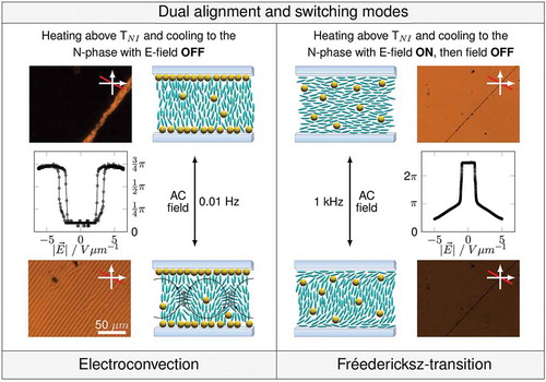
Qi et al. introduced an unprecedented dual alignment mode for nematic dispersions containing alkyl-functionalised gold NPs,[Citation58] where two different switching modes can be addressed, depending on the sample’s prior thermal and electrical treatment. After filling the dispersion into a LC test cell prepared with rubbed polyimide alignment layers for planar alignment, the NPs induce homeotropic alignment and the sample appears dark between crossed polarisers. Although clearly exhibiting a positive dielectric anisotropy,[Citation59] this dark state switches to a bright state under the influence of low frequency electric fields applied perpendicular to the substrates. In contrast, when heated to the isotropic phase and cooled to the nematic phase under the influence of an external AC field, the dispersion shows homogeneous planar alignment as expected to be induced by the initial alignment layers. This planar alignment then remains stable also in the absence of an electric field and allows the dispersion to undergo a Fréedericksz-transition from planar to homeotropic, resulting in a switching from bright to dark between crossed polarisers.
We thoroughly investigated this unusual switching behaviour by means of electro-optical studies, and we identified the reversed switching (dark–bright) to be an example of electrohydrodynamic instabilities leading to the formation of birefringent convection rolls. This unusual scenario resembles the recent experimental observations on electroconvection in nematic LCs with initial homeotropic alignment, positive dielectric anisotropy and negative conductivity anisotropy.[Citation60–Citation62] The observed Williams-domains reproducibly form parallel stripe patterns perpendicular to the easy axis of the test cell, indicating that the initial polyimide alignment layer, although being superimposed by NPs, still has an effect on the liquid crystal alignment. A schematic overview over the NP-induced dual alignment and reverse switching observations is given in .
Figure 3. Schematic summary of the nanoparticle-induced dual alignment and reverse switching modes. Left: Slow cooling of a dispersion containing 5% (w) dodecylthiol-capped gold NPs in FELIX-2900-03 from the isotropic to the nematic phase induces homeotropic alignment in the field-OFF state. Low frequent AC fields then cause the formation of birefringent convection rolls which constitute the observed reverse switching mode. Right: Cooling the same test cell from isotropic to the nematic phase with external AC field-ON induces planar alignment when the electric field is switched OFF. External electric fields then allow the dispersion to undergo the ‘normal’ switching mode for hosts with positive dielectric anisotropy, a Fréedericksz-transition is observed.
Nanoparticles interfering with initial alignment layers
The competing influences of the initial polyimide alignment layers, which promote planar alignment, and the NPs, which promote homeotropic alignment, provide an intriguingly interesting environment for unusual electro-optic switching effects of nematic nanodispersions. It is important to notice that these interactions of NPs with the alignment layers of electro-optic test cells considerably complicate the electro-optic characterisation of liquid crystal/NP composites, as we explain in detail in reference.[Citation63]
The most widely used electro-optical characterisation routine for nematic materials follows the Single-Cell-approach as introduced by Clark [Citation64] and refined by Wu.[Citation65,Citation66] It utilises a homogeneously oriented LC test cell with planar (positive Δε) or homeotropic (negative Δε) initial alignment, strong boundary conditions and an electric or magnetic field perpendicular to the substrates to reorient the liquid crystal. This setup allows the determination of threshold voltage VTh, permittivities perpendicular (ε⊥) and parallel (ε║) to the director as well as switching times (τrise, τdecay) by using a single cell only. The well-known theory for the Fréedericksz-transition [Citation67] can be deployed to derive information about the elastic (Kii) and viscous (γ1) properties of the nematic material. The Single-Cell approach represents a fast and powerful characterisation method for nematic LCs and has been successfully implemented in automatic liquid crystal test devices like the ALCT from Instec, Inc. (USA) or the LCAS by LC Vision (USA).
However, a meaningful connection of experimentally accessible measures (VTh, Δε, τrise, τdecay) and respective physical properties (Kii, S, γ1) requires a precise knowledge about the initial boundary conditions. This is usually ensured by using test cells with high quality alignment layers, for example rubbed polyimide,[Citation68] which ensure sufficiently high anchoring energy and negligible pretilt angles (for geometry, cf. ). Commercially available polyimide-coated test cells for planar alignment exhibit, depending on the manufacturer, pretilt angles between 1° and 3° (LC Vision, USA) or 0° < θ0 < 1° (E.H.C Co., Ltd., Japan), respectively. In case NPs superimpose these initial alignment layers, the well-defined boundary conditions get obscured and the theoretical approach does no longer match the experimental conditions. In consequence, additional attention to the anchoring conditions is necessary when the electro-optical properties of nematic nanodispersions are to be investigated.
Figure 4. Illustration of cell geometry in the field OFF state (left) and under the influence of an external electric field (right). Reproduced from Urbanski et al. [Citation63] with permission by Wiley-VCH.
![Figure 4. Illustration of cell geometry in the field OFF state (left) and under the influence of an external electric field (right). Reproduced from Urbanski et al. [Citation63] with permission by Wiley-VCH.](/cms/asset/3489ce0b-5767-4850-a06f-da3a914ada29/tlcy_a_1059586_f0004_c.jpg)
The threshold voltage VTh of the Fréedericksz transition is given by the onset of director deformations when the electric or magnetic torque overcomes the restoring elastic torque of the nematic material and can be expressed by the relation . In a strict sense, this threshold is only defined for zero pretilt angle (θ0 = 0), as any finite pretilt angle blurs the threshold and leads to a continuous director field deformation. For sufficiently small pretilt angles (θ0 < 3°), this deviation is small and can be neglected, which is usually the case for undoped nematic LCs. Any larger pretilt angle leads to a significant director field deformation at lower field strengths compared to zero pretilt, and in consequence to lower quasi-threshold voltages. Although in such case the light transmission at crossed polarisers switches at lower external fields, this change cannot be connected to an influence of NPs on the elastic properties of the dispersion, but is solely caused by a change in anchoring conditions. Furthermore, any finite pretilt angle increases the cell capacitance in the field-OFF state, which seemingly increases ε⊥ and therefore decreases the dielectric anisotropy Δε of the dispersion. This effect, too, cannot be connected to a decrease of nematic order parameter S in the bulk of the material.
A second influence on the threshold voltage VTh is given by the polar anchoring energy W at the confining substrates of the test cell, where W is the coefficient of an assumed Rapini-Papoular potential for the anchoring energy, fs = 1/2W sin2(θ – θ0).[Citation69] It is known that weak anchoring conditions lead to smaller apparent threshold voltages, although the elastic properties of the bulk remain unaffected. Also in the case of NPs reducing the polar anchoring energy at the confining substrates, the relation cannot be used to derive elastic properties of the bulk from the measured threshold voltage VTh.
In order to take these considerations into account and to distinguish between NP-induced effects on the anchoring conditions and effects of NP doping on the LC bulk properties, we employed numerical simulation routines. Based on a one-dimensional model of a splay type Fréedericksz-transition in test cells with planar initial alignment (cf. ), we calculated the field-dependent theoretical director field distribution throughout the test cell. Our algorithm follows the approach by Welford and Sambles [Citation70] and is based on the work of Deuling [Citation71] with extension to arbitrary initial tilt angles θ0. This extended simulation model includes five parameters (K11, K33, ε⊥, ε║, θ0) which were varied until the mean square difference between the calculated capacitance response and the measured capacitance data was minimised. We found this approach suitable to reproduce the measured capacitance responses for pristine hosts and doped samples with high accuracy, and the obtained model parameters were assumed to be directly connected to the respective physical properties of the nanocomposites under investigation.
In our recent study, we showed that the very commonly used simplified One-Constant approximation (K11 = K33 =K) yields reliable results for the threshold VTh and the permittivities ε⊥ and ε║ only under the condition of small initial tilt angles (θ0 < 2°) and strong anchoring conditions (W = ∞).[Citation63] Experimental measurements of the polar anchoring strength W at the nematic LC/substrate interface followed the high-field approach by Yokoyama and van Sprang [Citation72,Citation73] and revealed a negligible influence of NPs on the anchoring strength.[Citation63]
We found that the presence of hexadecylamine-capped CdSe quantum dots in the host 5CB decreases the elastic constants K11 and K33 and leads to an increase of the initial tilt angle θ0, cf. . The decrease of elastic constants is in agreement with earlier observations for CdSe quantum dots.[Citation51] The increase of initial tilt angle indicates a higher degree of surface coverage at higher doping concentrations and gives a strong hint for insufficient dispersibility.
Figure 5. Fitting results for hexadecylamine-capped CdSe quantum dots in the host 5CB. (a) Elastic constant K11 for splay deformations. (b) Initial tilt angle θ0. Nanoparticle doping leads to a slight decrease of elastic constant, which is in accordance to earlier observations. Additionally, a pronounced increase of initial tilt angle is found, presumably caused by NPs residing at the initial alignment layers of the test cell. Reproduced from Urbanski et al.[Citation63] with permission by Wiley-VCH.
![Figure 5. Fitting results for hexadecylamine-capped CdSe quantum dots in the host 5CB. (a) Elastic constant K11 for splay deformations. (b) Initial tilt angle θ0. Nanoparticle doping leads to a slight decrease of elastic constant, which is in accordance to earlier observations. Additionally, a pronounced increase of initial tilt angle is found, presumably caused by NPs residing at the initial alignment layers of the test cell. Reproduced from Urbanski et al.[Citation63] with permission by Wiley-VCH.](/cms/asset/2595c743-3aa7-410b-8738-c6a6dab9d782/tlcy_a_1059586_f0005_c.jpg)
A clear evidence for a temperature dependent shift of NPs from the surface to the bulk in polyimide-coated test cells was found for a dispersion containing 2.5% of silane-stabilised gold NPs with mesogenic corona in the apolar host FELIX-2900-03, cf. . While at high temperatures no change of pretilt angle compared to the pristine host is found, the dispersion reproducibly shows very large pretilt angles of more than 20° at lower temperatures. Additionally, a similar temperature-dependent influence of NPs on the splay elastic constant K11 is found: while at low temperatures the elastic constant K11 is comparable to the elastic constant of the pure host, the elastic constant decreases with increasing temperature. This correlation strongly indicates that at low temperatures, the NPs reside at the interfaces and affect the boundary conditions only while the bulk properties remain unchanged. At higher temperatures, the dispersibility of particles increases and they shift into the bulk, where they decrease the elastic constant while no longer affecting the boundary conditions. This observation is in good agreement with the aforementioned temperature-dependent reversible alignment change between planar and homeotropic, which is detectable by polarising optical microscopy. Our study reports for the first time a reversible NP-induced alignment change between two birefringent planar states, which is difficult to detect microscopically but requires a more sophisticated analysis of the electro-optical response.
Figure 6. Fitting results for silane-stabilised gold NPs with mesogenic corona in the host FELIX-2900-03. (a) Elastic constant Κ11 for splay deformations. (b) Initial tilt angle θ0. Nanoparticle doping is found to decrease the elastic constant. At low doping concentrations the nanoparticle do not affect the initial tilt angle θ0, while higher doping concentrations increase θ0. For the sample containing 2.5% (w) of NPs, a correlation between the increase of pretilt angle and the decrease of elastic constant is found: When at low temperatures the tilt angle is high, the elastic constant of the dispersion is comparable to the values of the pristine host. With decreasing tilt angle at higher temperatures the elastic constant also decreases, which indicates a movement of particles from the interface to the bulk. Reproduced from Urbanski et al.[Citation63] with permission by Wiley-VCH.
![Figure 6. Fitting results for silane-stabilised gold NPs with mesogenic corona in the host FELIX-2900-03. (a) Elastic constant Κ11 for splay deformations. (b) Initial tilt angle θ0. Nanoparticle doping is found to decrease the elastic constant. At low doping concentrations the nanoparticle do not affect the initial tilt angle θ0, while higher doping concentrations increase θ0. For the sample containing 2.5% (w) of NPs, a correlation between the increase of pretilt angle and the decrease of elastic constant is found: When at low temperatures the tilt angle is high, the elastic constant of the dispersion is comparable to the values of the pristine host. With decreasing tilt angle at higher temperatures the elastic constant also decreases, which indicates a movement of particles from the interface to the bulk. Reproduced from Urbanski et al.[Citation63] with permission by Wiley-VCH.](/cms/asset/80850ebd-376a-49ef-8a1a-399d49677d2f/tlcy_a_1059586_f0006_c.jpg)
Polarisation processes in nanoparticle dispersions
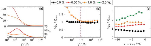
We also identified polarisation effects occurring in functional nanocomposites to be responsible for unusual results during the electro-optic characterisation of these composites. It is known that functionalised NPs dispersed in a nematic liquid crystal lead to the formation of Maxwell–Wagner–Sillars (MWS)-polarisation in the Hz or low kHz frequency region, as shown by Kobayashi et al.[Citation74] This type of polarisation processes can be observed in heterogeneous dielectric media composed of materials with different permittivity and conductivity at the mesoscopic interfaces between the respective components. In nematic NP dispersions, the dielectric relaxation frequency of the MWS-polarisation process depends on the material, size and coating of NPs and the electric and dielectric properties of the LC host. Kobayashi et al. showed that with higher doping concentrations, i.e. with increasing metal content in the dispersion, the relaxation frequency shifts to higher values. Simultaneously, their experiments showed that below the resonance frequency, the threshold voltage VTh strongly increases. Similar observations were also reported by Yoshida and coworkers [Citation4] and were confirmed by own experiments with alkylthiol functionalised or mesogenic functionalised gold NPs in the host 5CB, cf. . The increase of threshold is presumably caused by a reduction of the internal electric field due to internal polarisation processes and therefore not connected to an influence of NPs on the elastic properties or the dielectric anisotropy of the host. Also the refined numerical model of the Fréedericksz-transition described above does not hold for electro-optic measurements performed below the resonance frequency of the MWS-polarisation, as it does not take polarisation effects into account. In consequence, the occurrence of MWS-polarisation effects in the low kHz region restricts the choice of frequency for the electro-optic characterisation of NP dispersions to values above the resonance frequency.
Figure 7. Experimental data for dispersions containing dodecylthiol-capped gold NPs in the nematic host 5CB showing the influence of polarisation effects on the threshold voltage VTh of the Fréedericksz-transition. (a) Dielectric spectroscopy measurements showing Maxwell–Wagner–Sillars polarisation peaks in the kHz region for nanoparticle doped samples. (b) Experimental data proving a strong increase of threshold VTh below the resonance frequency (dashed line) of the MWS-relaxation. (c) Measurements of threshold voltage VTh at a fixed frequency of 1 kHz. The strong increase of threshold with increasing doping concentration is caused by a shift of the MWS-resonance with increasing metal content to higher frequencies.
Gold nanoparticles with silane-stabilised ligand shell
A promising development in the synthesis of thermally and chemically robust gold NPs as dopants for liquid crystalline hosts was introduced in 2013 by the Hegmann group.[Citation33,Citation75] The authors utilised a silane conjugation approach [Citation76] on 3-mercaptotrimethoxysilane-capped gold NPs with a second alkyltrimethoxysilane, resulting in well dispersible particles with robust ligand shell.
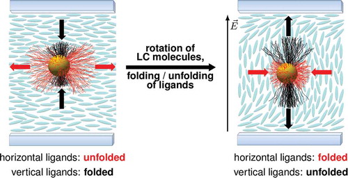
We found silane-stabilised gold particles with aliphatic corona to be well-dispersible in the nematic host FELIX-2900-03 without visible signs of agglomeration or influence on the anchoring conditions.[Citation75] The silanised particles stabilise the nematic phase at intermediate doping concentrations (0.5–1.0%(w)), while only for higher particle concentrations, a decrease of phase transition temperatures is observed. Comparable stabilising effects in the nematic phase due to NP doping have been reported for anisometrically shaped dopants like carbon nanotubes,[Citation77] polar ferroelectric NPs [Citation78] and tactoidally deformed gold NPs.[Citation6,Citation79] With reference to the theoretical predictions by Osipov and coworkers,[Citation35] we assume that also the silane stabilised ligand shell undergoes a tactoidal deformation due to anisometric interactions with the nematic host. The analysis of the electro-optic response reveals a clear improvement of performance for dispersions of silane-stabilised gold NPs, with decreased threshold voltages VTh and increased dielectric anisotropy Δε as shown in . Based on these observations, we assume that the field-induced reorientation of molecules during a Fréedericksz-transition is facilitated by a folding and unfolding of ligands without rotating the NP itself. A schematic presentation of this switching mechanism is shown in . This proposed mechanism extends the model by Draper et al.[Citation6] to NPs dispersed in a nematic host and their influence on the Fréedericksz-effect.
Figure 8. Plots of the dielectric anisotropy Δε (a) and threshold voltage VTh (b) for dispersions of silanised gold NPs in the apolar host FELIX-2900-03. For this NP/LC combination, nanoparticle doping clearly improves the electro-optic performance compared to the pristine host, leading to increased dielectric anisotropy and decreased driving voltages. Reproduced with permission from Mirzaei et al.[Citation75]
![Figure 8. Plots of the dielectric anisotropy Δε (a) and threshold voltage VTh (b) for dispersions of silanised gold NPs in the apolar host FELIX-2900-03. For this NP/LC combination, nanoparticle doping clearly improves the electro-optic performance compared to the pristine host, leading to increased dielectric anisotropy and decreased driving voltages. Reproduced with permission from Mirzaei et al.[Citation75]](/cms/asset/4f3abd27-a4a7-45e2-8017-3a122cb57627/tlcy_a_1059586_f0008_c.jpg)
Figure 9. Schematic illustration of our proposed switching mechanism leading to facilitated switching due to nanoparticle doping. Left: The ligand shell is deformed to a tactoidal shape due to anisometric interactions with the nematic host. Ligands along the uniaxial order of the host are fully unfolded and form two rigid poles, while ligands perpendicular to the nematic order are folded and form a soft equatorial ring. Right: Upon applying an external electric field the LC molecules rotate, whereas the particle remains unrotated. Instead, the previously folded ligands (black) unfold and the previously unfolded ligands fold (red), restoring the tactoidal shape of the nanoparticle parallel to the uniaxial order of LC molecules.
Conclusion and outlook
Functional composites of NPs dispersed in LCs enjoy high attention in topical research due to great opportunities for both basic science and promising future applications. The work reviewed in this article contributes an advanced insight of how NPs affect the alignment and electro-optic response of a nematic host material and offers resilient explanation models for numerous observed doping effects.
We stressed that the electro-optical performance of nematic LCs does not only depend on the bulk properties of the material, but also strongly on the boundary conditions at the confining substrates. Adding small amounts of NPs can significantly affect both aspects, so that observed doping phenomena usually result from an intermixing of NP effects on alignment layers and bulk properties. We identified the dispersibility of functionalised NPs in the nematic host to be one of the key factors determining the ratio between surface and bulk effects. An insufficient dispersibility of NPs leads to a repulsion of particles from the nematic phase onto the substrates, where particles interfere with the initial alignment layers. A strong surface coverage then causes homeotropic alignment, which constitutes the foundation for unusual textural effects or reverses switching phenomena. An intermediate degree of NP surface coverage leads to an increase of initial tilt angle θ0 combined with seemingly reduced dielectric anisotropy Δε and apparently lower threshold voltages VTh compared to the pristine host. We introduced an extended numerical simulations routine to extract the actual values for Kii, Δε and θ0 from electro-optic data and identified MWS polarisation processes as additional source for a NP-induced increase of VTh. Only particles with a high dispersibility in the nematic host are homogeneously dispersed in the LC phase and their influence on the alignment layers is negligible. A schematic summary of these three fundamental degrees of dispersibility is given in . We report an example of improved electro-optical performance by doping a nematic host with silane-stabilised gold NPs, a class of NPs offering great potential as thermally and chemically robust dopant for liquid crystalline hosts.
Figure 10. Illustrations of three degrees of dispersibility identified by the dependence of the capacitance (C) and light transmission (I) between crossed polarisers on reduced voltage. Left: Poor dispersibility leads to an expulsion of particles to the substrates and induces homeotropic alignment. Centre: Intermediate dispersibility affects the surface tilt angle and blurs the threshold of the field-dependent capacitance and light transmission responses. Right: Good dispersibility leads to the formation of homogeneous dispersions with a well-defined threshold for the Fréedericksz-effect. Reproduced from Urbanski et al. [Citation65] with permission by Wiley-VCH.
![Figure 10. Illustrations of three degrees of dispersibility identified by the dependence of the capacitance (C) and light transmission (I) between crossed polarisers on reduced voltage. Left: Poor dispersibility leads to an expulsion of particles to the substrates and induces homeotropic alignment. Centre: Intermediate dispersibility affects the surface tilt angle and blurs the threshold of the field-dependent capacitance and light transmission responses. Right: Good dispersibility leads to the formation of homogeneous dispersions with a well-defined threshold for the Fréedericksz-effect. Reproduced from Urbanski et al. [Citation65] with permission by Wiley-VCH.](/cms/asset/18c5c1e0-45c9-49a2-bef8-6bdb3e7c7cc9/tlcy_a_1059586_f0010_c.jpg)
Our results on the impact of NPs on the electro-optic properties of nematic LCs underline the complexity of the interactions between dopant, host and confining substrates. For future work in this topical field, we hope that researchers will benefit from our classification into surface and bulk dominated doping effects as well as from the refined electro-optical characterisation method. Hopefully, this will help to validate opposing reports about the influence of NPs on the physical properties of nematic hosts, identify the benefits and pave the way towards new and fascinating applications.
Disclosure statement
No potential conflict of interest was reported by the author.
Acknowledgements
The results reviewed in this article were elaborated in the Kitzerow group at the University of Paderborn, Germany.
Additional information
Funding
References
- Qi H, Hegmann T. Formation of periodic stripe patterns in nematic liquid crystals doped with functionalized gold nanoparticles. J Mater Chem. 2006;16:4197–4205.
- Ouskova E, Buchnev O, Reshetnyak V, et al. Dielectric relaxation spectroscopy of a nematic liquid crystal doped with ferroelectric Sn 2 P 2 S 6 nanoparticles. Liq Cryst. 2003;30:1235–1239. doi:10.1080/02678290310001601996.
- Li F, Buchnev O, Cheon CI, et al. Orientational coupling amplification in ferroelectric nematic colloids. Phys Rev Lett. 2006;97:147801/1–4.
- Yoshida H, Kawamoto K, Kubo H, et al. Nanoparticle-dispersed liquid crystals fabricated by sputter doping. Adv Mater. 2010;22:622–626. doi:10.1002/adma.v22:5.
- Cho M-J, Park H-G, Jeong H-C, et al. Superior fast switching of liquid crystal devices using graphene quantum dots. Liq Cryst. 2014;41:761–767. doi:10.1080/02678292.2014.889233.
- Draper M, Saez IM, Cowling SJ, et al. Self-assembly and shape morphology of liquid crystalline gold metamaterials. Adv Funct Mat. 2011;21:1260–1278. doi:10.1002/adfm.201001606.
- Mang X, Zeng X, Tang B, et al. Control of anisotropic self-assembly of gold nanoparticles coated with mesogens. J Mater Chem. 2012;22:11101–11106.
- Lewandowski W, Wójcik M, Górecka E. Metal nanoparticles with liquid-crystalline ligands: controlling nanoparticle superlattice structure and properties. Chem Phys Chem. 2014;15:1283–1295. doi:10.1002/cphc.201301194.
- Dintinger J, Tang B-J, Zeng X, et al. A self-organized anisotropic liquid-crystal plasmonic metamaterial. Adv Mater. 2013;25:1999–2004. doi:10.1002/adma.201203965.
- Pratibha R, Park K, Smalyukh II, et al. Tunable optical metamaterial based on liquid crystal-gold nanosphere composite. Optics Express. 2009;17:19459–19469.
- Gardner DF, Evans JS, Smalyukh II. Towards reconfigurable optical metamaterials: colloidal nanoparticle self-assembly and self-alignment in liquid crystals. Mol Cryst Liq Cryst. 2011;545:1227–1245. doi:10.1080/15421406.2011.571966.
- Koenig GM, Meli JM-V, Park J-S, et al. Coupling of the plasmon resonances of chemically functionalized gold nanoparticles to local order in thermotropic liquid crystals. Chem Mater. 2007;19:1053–1061. doi:10.1021/cm062438p.
- Bisoyi HK, Kumar S. Liquid-crystal nanoscience: an emerging avenue of soft self-assembly. Chem Soc Rev. 2011;40:306–319. doi:10.1039/B901793N.
- Saliba S, Mingotaud C, Kahn ML, et al. Liquid crystalline thermotropic and lyotropic nanohybrids. Nanoscale. 2013;5:6641–6661.
- Loudet J-C, Barois P, Poulin P. Colloidal ordering from phase separation in a liquid-crystalline continuous phase. Nature. 2000;407:611–613. doi:10.1038/35036539.
- West JL, Glushchenko A, Liao G. Drag on particles in a nematic suspension by a moving nematic-isotropic interface. Phys Rev E. 2002;66:012702–1. doi:10.1103/PhysRevE.66.012702.
- Voloschenko D, Pishnyak OP, Shiyanovskii SV, et al. Effect of director distortions on morphologies of phase separation in liquid crystals. Phys Rev E. 2002;65:060701–1. doi:10.1103/PhysRevE.65.060701.
- Lubensky TC, Pettey D, Currier N, et al. Topological defects and interactions in nematic emulsions. Phys Rev E. 1998;57:610–625. doi:10.1103/PhysRevE.57.610.
- Stark H. Director field configurations around a spherical particle in a nematic liquid crystal. Eur Phys J B. 1999;10:311–321. doi:10.1007/s100510050860.
- Poulin P, Stark H, Lubensky TC, et al. Novel colloidal interactions in anisotropic fluids. Science. 1997;275:1770–1773. doi:10.1126/science.275.5307.1770.
- Lapointe C, Hultgren AD, Silevitch ME, et al. Elastic torque and the levitation of metal wires by a nematic liquid crystal. Science. 2004;303:652–655. doi:10.1126/science.1092608.
- Liao G, Smalyukh II, Kelly JR, et al. Electrorotation of colloidal particles in liquid crystals. Phys Rev E. 2005;72:031704. doi:10.1103/PhysRevE.72.031704.
- Lapointe C, Mason TG, Smalyukh II. Shape-controlled colloidal interactions in nematic liquid crystals. Science. 2009;326:1083–1086. doi:10.1126/science.1176587.
- Urbanski M, Piegdon KA, Meier C, et al. Investigations on the director field around microdisc resonators. Liq Cryst. 2011;38:475–482. doi:10.1080/02678292.2011.552742.
- De Gennes PG. The physics of liquid crystals. Oxford: Oxford University Press; 1974.
- Kleman M. Points, lines and walls. New York: John Wiley & Sons; 1983.
- Coursault D, Grand J, Zappone B, et al. Linear self-assembly of nanoparticles within liquid crystal defect arrays. Adv Mater. 2012;24:1461–1465. doi:10.1002/adma.201103791.
- Milette J, Relaix S, Lavigne C, et al. Reversible long-range patterning of gold nanoparticles by smectic liquid crystals. Soft Matter. 2012;8:6593–6598.
- Yoshida H, Tanaka Y, Kawamoto K, et al. Nanoparticle-stabilized cholesteric blue phase. Appl Phys Expr. 2009;2:121501.
- Ravnik M, Alexander GP, Yeomans JM, et al. Three-dimensional colloidal crystals in liquid crystalline blue phases. Proc Natl Acad Sci. 2011;108:5188–5192. doi:10.1073/pnas.1015831108.
- Karatairi E, Rožič B, Kutnjak Z, et al. Nanoparticle-induced widening of the temperature range of liquid-crystalline blue phases. Phys Rev E. 2010;81:041703. doi:10.1103/PhysRevE.81.041703.
- Kikuchi H, Yokota M, Hisakado Y, et al. Polymer-stabilized liquid crystal blue phases. Nat Mater. 2002;1:64–68. doi:10.1038/nmat712.
- Mirzaei J, Urbanski M, Kitzerow H-S, et al. Synthesis of liquid crystal silane-functionalized gold nanoparticles and their effects on the optical and electro-optic properties of a structurally related nematic liquid crystal. Chem Phys Chem. 2014;15:1381–1394. doi:10.1002/cphc.201301052.
- Milette J, Toadar V, Reven L, et al. Tuning the miscibility of gold nanoparticles dispersed in liquid crystals via the thiol-for-DMAP reaction. J Mater Chem. 2011;21:9043.
- Gorkunov MV, Osipov MA. Mean-field theory of a nematic liquid crystal doped with anisotropic nanoparticles. Soft Matter. 2011;7:4348–4356.
- Gorkunov MV, Shandryuk GA, Shatalova AM, et al. Phase separation effects and the nematic-isotropic transition in polymer and low molecular weight liquid crystals doped with nanoparticles. Soft Matter. 2013;9:3578–3588.
- Nealon GL, Greget R, Dominguez C, et al. Liquid-crystalline nanoparticles: hybrid design and mesophase structures. Beilstein J Org Chem. 2012;8:349–370. doi:10.3762/bjoc.8.39.
- Scalia G, Lagerwall JPF, Schymura S, et al. Carbon nanotubes in liquid crystals as versatile functional materials. Phys Stat Sol B. 2007;244:4212–4217. doi:10.1002/(ISSN)1521-3951.
- Dierking I, Scalia G, Morales P, et al. Aligning and reorienting carbon nanotubes with nematic liquid crystals. Adv Mater. 2004;16:865–869. doi:10.1002/(ISSN)1521-4095.
- Ji Y, Huang YY, Terentjev EM. Dissolving and aligning carbon nanotubes in thermotropic liquid crystals. Langmuir. 2011;27:13254–13260. doi:10.1021/la202790a.
- Kühnast M, Tschierske C, Lagerwall J. Tailor-designed polyphilic promotors for stabilizing dispersions of carbon nanotubes in liquid crystals. Chem Comm. 2010;46:6989–6991.
- Schymura S, Kühnast M, Lutz V, et al. Towards efficient dispersion of carbon nanotubes in thermotropic liquid crystals. Adv Funct Mater. 2010;20:3350–3357. doi:10.1002/adfm.201000539.
- Soulé ER, Milette J, Reven L, et al. Phase equilibrium and structure formation in gold nanoparticles-nematic liquid crystal composites: experiments and theory. Soft Matter. 2012;8:2860–2866.
- Choudhary A, Singh G, Biradar AM. Advances in gold nanoparticle-liquid crystal composites. Nanoscale. 2014;6:7743–7756.
- Mirzaei J, Reznikov M, Hegmann T. Quantum dots as liquid crystal dopants. J Mater Chem. 2012;22:22350–22365.
- Liao S-W, Hsieh C-T, Kuo C-C, et al. Voltage-assisted ion reduction in liquid crystal-silica nanoparticle dispersions. Appl Phys Lett. 2012;101:161906.
- Cook G, Reshetnyak VY, Ziolo RF, et al. Asymmetric Freedericksz transitions from symmetric liquid crystal cells doped with harvested ferroelectric nanoparticles. Optics Express. 2010;18:17339–17345.
- Lagerwall JPF, Scalia G. Carbon nanotubes in liquid crystals. J Mater Chem. 2008;18:2890–2898.
- Qi H, Hegmann T. Liquid crystal–gold nanoparticle composites. Liq Cryst Today. 2011;20:102–114. doi:10.1080/1358314X.2011.610133.
- Qi H, Hegmann T. Multiple alignment modes for ematic liquid crystals doped with alkylthiol-capped gold nanoparticles. Appl Mater Interf. 2009;1:1731–1738. doi:10.1021/am9002815.
- Kinkead B, Hegmann T. Effects of size, capping agent, and concentration of CdSe and CdTe quantum dots doped into a nematic liquid crystal on the optical and electro-optic properties of the final colloidal liquid crystal mixture. J Mater Chem. 2010;20:448–458. doi:10.1039/B911641A.
- Urbanski M, Kinkead B, Hegmann T, et al. Director field of birefringent stripes in liquid crystal/nanoparticle dispersions. Liq Cryst. 2010;37:1151–1156. doi:10.1080/02678292.2010.489160.
- Mirzaei J, Urbanski M, Yu K, et al. Nanocomposites of a nematic liquid crystal doped with magic-sized CdSe quantum dots. J Mater Chem. 2011;21:12710–12716.
- Bezrodna T, Chashechnikova I, Gavrilko T, et al. Structure formation and its influence on thermodynamic and optical properties of montmorillonite organoclay-5CB liquid crystal nanocomposites. Liq Cryst. 2008;35:265–274. doi:10.1080/02678290701830626.
- Da Cruz C, Sandre O, Cabuil V. Phase behavior of nanoparticles in a thermotropic liquid crystal. J Phys Chem B. 2005;109:14292–14299. doi:10.1021/jp0455024.
- Reznikov M, Sharma A, Hegmann T. Ink-jet printed nanoparticle alignment layers: easy design and fabrication of patterned alignment layers for nematic liquid crystals. Part Part Syst Charact. 2014;31:257–265. doi:10.1002/ppsc.201300248.
- Cseh L, Mehl GH. Structure–property relationships in nematic gold nanoparticles. J Mater Chem. 2007;17:311–315. doi:10.1039/B614046G.
- Qi H, Kinkead B, Hegmann T. Unprecedented dual alignment mode and Freedericksz transition in planar nematic liquid crystal cells doped with gold nanoclusters. Adv Funct Mater. 2008;18:212–221.
- Urbanski M, Kinkead B, Qi H, et al. Electroconvection in nematic liquid crystals via nanoparticle doping. Nanoscale. 2010;2:1118–1121.
- Buka A, Dressel B, Kramer L, et al. Direct transition to electroconvection in a homeotropic nematic liquid crystal. Chaos. 2004;14:793–802.
- Buka A, Dressel B, Kramer L, et al. Isotropic convection scenarios in an anisotropic fluid. Phys Rev Lett. 2004;93:044502. doi:10.1103/PhysRevLett.93.044502.
- Buka A, Dressel B, Otowski W, et al. Electroconvection in nematic liquid crystals with positive dielectric and negative conductivity anisotropy. Phys Rev E. 2002;66:051713. doi:10.1103/PhysRevE.66.051713.
- Urbanski M, Mirzaei J, Hegmann T, et al. Nanoparticle doping in nematic liquid crystals: distinction between surface and bulk effects by numerical simulations. Chem Phys Chem. 2014;15:1395–1404. doi:10.1002/cphc.201301054.
- Clark MG, Raynes EP, Smith RA, et al. Measurement of the permittivity of nematic liquid crystals in magnetic and electric fields using extrapolation procedures. J Phys D: Appl Phys. 1980;13:2151–2164. doi:10.1088/0022-3727/13/11/025.
- Wu S-T, Wu C-S. Experimental confirmation of the Osipov-Terentjev theory on the viscosity of nematic liquid crystals. Phys Rev A. 1990;42:2219–2227. doi:10.1103/PhysRevA.42.2219.
- Wu S-T, Coates D, Bartmann E. Physical properties of chlorinated liquid crystals. Liq Cryst. 1991;10:635–646. doi:10.1080/02678299108241731.
- Demus D, Goodby JW, Gray GW, et al. Handbook of liquid crystals. Weinheim: WILEY-VCH; 1998. p. 270–272.
- Jerome B. Surface effects and anchoring in liquid crystals. Rep Prog Phys. 1991;54:391–451. doi:10.1088/0034-4885/54/3/002.
- Blinov LM, Chigrinov VG. Electrooptic effects in liquid crystal materials. New York: Springer; 1994.
- Welford KR, Sambles JR. Analysis of electric field induced deformations in a nematic liquid crystal for any applied field. Liq Cryst. 1987;147:25–42. doi:10.1080/00268948708084622.
- Deuling HJ. Deformation pattern of twisted nematic liquid crystal layers in an electric field. Mol Cryst Liq Cryst. 1974;27:81–93. doi:10.1080/15421407408083121.
- Yokoyama H, Van Sprang HA. A novel method for determining the anchoring energy function at a nematic liquid crystal-wall interface from director distortions at high fields. J Appl Phys. 1985;57:4520–4526.
- Nastishin YA, Polak RD, Shiyanovskii SV, et al. Nematic polar anchoring strength measured by electric field techniques. J Appl Phys. 1999;86:4199–4213.
- Kobayashi S, Miyama T, Nishida N, et al. Dielectric spectroscopy of metal nanoparticle doped liquid crystal displays exhibiting frequency modulation response. J Display Technol. 2006;2:121–129. doi:10.1109/JDT.2006.872306.
- Mirzaei J, Urbanski M, Kitzerow H-S, et al. Hydrophobic gold nanoparticles via silane conjugation: chemically and thermally robust nanoparticles as dopants for nematic liquid crystals. Phil Trans R Soc A. 2013;371:20120256. doi:10.1098/rsta.2012.0256.
- Jana NR, Earhart C, Ying JY. Synthesis of water-soluble and functionalized nanoparticles by silica coating. Chem Mater. 2007;19:5074–5082. doi:10.1021/cm071368z.
- Duran H, Gazdecki B, Yamashita A, et al. Effect of carbon nanotubes on phase transitions of nematic liquid crystals. Liq Cryst. 2005;32:815–821. doi:10.1080/02678290500191204.
- Lopatina LM, Selinger JV. Theory of ferroelectric nanoparticles in nematic liquid crystals. Phys Rev Lett. 2009;102:197802. doi:10.1103/PhysRevLett.102.197802.
- Khatua S, Manna P, Chang W-S, et al. Plasmonic nanoparticles−liquid crystal composites. J Phys Chem C. 2010;114:7251–7257. doi:10.1021/jp907923v.