Abstract
This paper shows how to build Luenberger observers for linear time-invariant systems modelled by bond graph. The methods are based on Luenberger's algebraic methods to design both full-order and reduced-order observers. The procedure for reduced-order observers uses the bicausality concept to simplify some classical matrix calculations (the calculation of matrix inverses is not needed), which is an important improvement mainly for large-scale systems. The calculation of the observer gains is based on the pole-placement techniques for linear systems modelled by bond graphs. As an application, both observers are designed for a vehicle suspension modelled by bond graphs.
1 Introduction
In some applications of automatic control, it is assumed that the entire state vector is available for feedback. Often, however, this is not the case; it is either impractical to measure some or all of the states, or the quality of the measurement, in terms of the signal-to-noise ratio, is poor enough to reduce the utility of the compensator. In these instances, we must estimate the unavailable state variables, using an observer. This approach normally allows implementation of the compensator with an acceptable performance. If an observer is used to provide estimates of all state variables, it is referred to as a full-order state observer. Sometimes, however, it is possible to obtain a satisfactory measurement of some, but not all, states. In these instances, a reduced-order state observer may be used to estimate only the non-accessible states.
Considering an observable model, Luenberger observers [Citation1] can be designed in such a way that the difference between the actual system states and the states of the observer can be reduced to zero. Luenberger's methods consider a system modelled by a linear time-invariant state equation:
1.1 Full-order observer
Under observability assumptions on the pair [A, C] and the non-existence of redundant outputs, a full-order observer for Equationequation (1) can be readily constructed as:
1.2 Reduced-order observers
The principal advantage of implementing a reduced-order observer is that it will estimate only those state variables that cannot be accessible by the measurements; the order of the observer model will be lower than the order of a complete order observer, and thus the computational cost to estimate these variables decreases.
Luenberger's method for building reduced-order observers [Citation2 – Citation Citation4] divides the state variables of the model into accessible variables and non-accessible variables.
Definition 1
The accessible variables are the state variables that can be directly measured from a sensor or can be calculated directly from the measurement.
With this classification, the state equation of the system can be written as a function of the accessible (xa ∈ ℜ m ) and non-accessible (xb ∈ ℜ n-m ) variables as follows:
EquationEquation (6) needs the inversion of a Ca submatrix. Because of this, xa must be selected such that rank(Ca ) = m to guarantee the existence of
Remark
One special type of accessible state variable is the measurable state variable. This variable is a state variable that can be measured directly from a sensor; if all outputs are measurable state variables, then Ca is equal to the identity matrix, Cb is equal to zero, and thus the Equationequation (6) is simplified.
From the state Equationequation (4) Luenberger's method proposes the estimated state as:
As xb is non-accessible, in Equationequation (7) the term
This observer gives the following dynamics for the estimation error,
1.3 Design of the observer: calculation of the gain matrix K
The pole assignment method is a classical technique to design linear observers. When a full-order observer is designed, the observability of the pair (A, C) is needed to fix the eigenvalues of (A – KC), as shown in Theorem 1:
Theorem 1
The eigenvalues of (A – KC) can be fixed arbitrarily if and only if the pair (A, C) is observable. Then, for asymptotically stable error dynamics the gain vector K should be chosen such that the eigenvalues of (A – KC) lie strictly in the left half plane. For designing reduced-order observers, Luenberger [Citation3] showed the result of Theorem 2.
Theorem 2
If the pair (A, C) is observable, the pair
According to Theorems 1 and 2, selecting the eigenvalues of the observer, the calculation of K may be based on the characteristic polynomial coefficients obtained for the observer. Many authors have studied this problem using algebraic, geometric and graphical approaches. In particular, Pichardo-Almarza et al. [Citation5, Citation6] used the results of Rahmani et al. [Citation7] to calculate the gain of reduced-order observers directly from a bond-graph model.
The main objective of the present work is to provide a bond-graph approach to build and design Luenberger observers for linear time-invariant systems. As an application, the observers are designed for a 1/2 vehicle passive mechanical suspension, which has two measurements that depend on several states variables.
This paper is organized as follows: Section 2 shows the bond-graph implementation of Luenberger observers. Section 3 shows the principles to design the observer starting from a bond-graph model. Section 4 proposes the implementation of the observers on an example. Finally, Section 5 presents the conclusions of this work.
2 Bond-graph approach to build the observers
The bond-graph implementation is based on Luenberger's methods detailed in the previous section. The observer bond graphs are equivalent to Equationequations (2) and Equation(9), and thus, the system's bond-graph model must be equivalent to Equationequation (1). For the sake of clarity, it is supposed that in the bond-graph model, there are no causal loops between R-elements or derivative causalities that could generate an implicit state equation. In a bond-graph model, there may be derivative causalities or causal loops between R-elements that generate an implicit state equation, which means that the state equation has the following form:
The use of bond graphs allows techniques of structural analysis to be used to determine several different properties of a model. In this paper, the results shown by Sueur and Dauphin-Tanguy [Citation8] will be used to analyse the model of the system before building the linear observer. The first two steps of the procedure to build both observers (full-order and reduced-order) are the same. The first step is related to the verification of the non-existence of redundant outputs for observability purpose, and the second is related to the verification of the structural observability of the model.
Step 1. Verification of the non-existence of redundant outputs
From a bond-graph point of view, the definition of bond-graph rank (bg-rank) can be used to confirm the rank of the model's matrices. The bg-rank is a structural rank in the sense of graph theory but corresponds in fact to the numerical rank because it takes into account parameter dependency through the causality. Sueur and Dauphin-Tanguy [Citation8] have shown the following property for the bg-rank[C]:
Property 1
The bg-rank[C] is equal to the number of detectors in a bond-graph model that can be dualized without creating causality conflicts at the junctions while accepting the change in causality in the dynamical elements. This property provides information about the existence of redundant outputs. Some redundant outputs might exist and might be neglected; thus, taking only the outputs in the detectors that can be dualized without any causality conflict, the bg-rank[C] will be equal to the number of non-redundant outputs: bg-rank[C] = m.
Step 2. Verification of the structural observability
The verification of structural observability of the bond-graph model is made using the technique proposed by Sueur and Dauphin-Tanguy [Citation8]. They have shown that if all dynamical elements in integral causality are causally connected with a detector, and all the I-C elements in integral causality are in derivative causality when a derivative assignment is performed over the initial bond graph (with an eventual dualization of some detectors), then the model is structurally state-observable by the detectors.
2.1 Procedure to build full-order observers
Karnopp [Citation9] proposed a method for bond-graph models to build both complete-order observers and reduced-order observers for linear systems. In his work, the method used the bond-graph model basically for the architecture of the observer. The observer gain is calculated using classical algebraic methods. In the present work, the architecture of full-order observers shown by Karnopp is used.
After applying Step 1 to select only the non-redundant outputs and Step 2 to confirm the structural observability, there is only one additional step to be added for building full-order observers. Thus, the procedure can be summarized as follows:
| 1. | Step 1 and Step 2. See above. | ||||
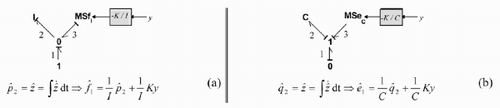
| 2. | Step 3. Linear output injection: addition of the term | ||||
Figure 1. Addition of the term to the dynamic element of the observer model.
2.2 Procedure to build reduced-order observers
The bond-graph implementation will calculate the estimated state using the auxiliary variable,
Figure 2. Procedure to build the reduced order observer.
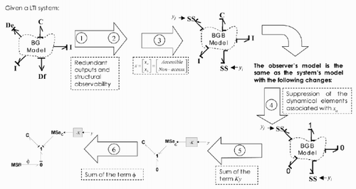
The relevant steps in this procedure are 3 and 5, because they show how to use the bicausality concept in the bond-graph implementation of the observer. Step 3 shows how to avoid the calculation of
| 1. | Step 3. Selection of xa , verification of rank (Ca ) = m and calculation of Ca and Cb . | ||||
| 2. | Step 3.1. Selection of xa. | ||||
Definition 2
The accessible states in the bond-graph model are the state variables causally connected with the outputs. This means that xa are state variables associated with the dynamical elements that have a direct causal path (or an indirect causal path through a R-element) with a detector.
The first condition that xa must satisfy is: dim(xa ) = bg-rank[C] = m. Afterwards, xa must be selected such that the Ca submatrix is invertible.
Step 3.2. Verification of bg-rank of Ca submatrix: Invertibility
Taking only the outputs in the detectors that can be dualized without any causality conflict, Property 1 implies that there exists an invertible submatrix of C with dimensions m × m, called Ca , corresponding to a selection of components xa .
After applying Property 1 to select the non-redundant outputs, the bicausality concept can be used to select the xa vector guaranteeing the existence of Ca −1.
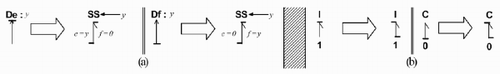
The computational capabilities of the bicausality concept have shown that this is an adequate tool for solving the problem of inverse systems [Citation10]. The bicausality allows a variable to be fixed or imposed at the same time, and its conjugate as bicausal bonds decouples the effort and flow causalities. In the context of the inversion problem, imposing the output variable without modifying the energy structure (or constraint equations) of the system can be carried out by an SS element having a flow source/effort source causality [Citation11].
From Property 1, it is possible to determine bg-rank[C] by means of the dualization of detectors. When this procedure is carried out, the conjugate variable equals zero, because the detector is supposed to be ideal (with no power being dissipated or stored). Then, to obtain information on
Theorem 3
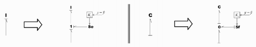
The inverse of Ca submatrix exists (or the bg-rank[Ca ] = m), if the following operations can be made in the bond-graph model without introducing any causality conflict:
| 1. | All detectors are substituted by SS elements (). | ||||
| 2. | The integral causality of the dynamical elements associated with xa change into a bicausality (). | ||||
| 3. | The dynamical elements associated with xb stay in integral causality. | ||||
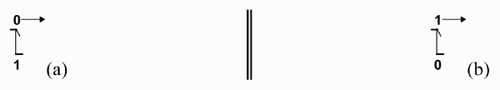
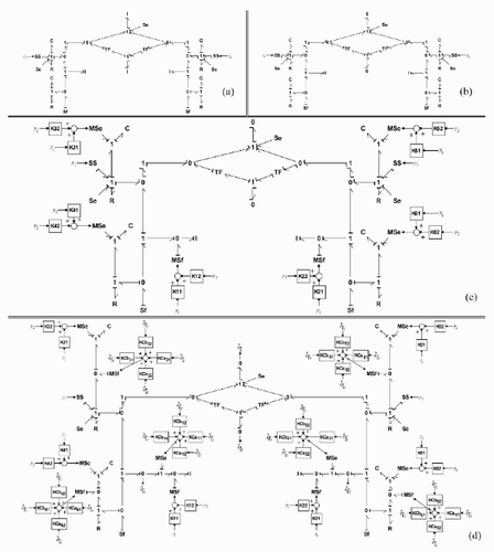
Figure 3. (a) Substitution of detectors by SS elements. (b) Bicausality of elements associated with xa .
Proof
Consider the junction structure equation of the initial bond-graph model:
Obviously, there are two possible ways to invert the output equation in Equationequation (4), directly with the inverse of Ca submatrix, or using the bicausality assignment. The same equation has to be obtained, so Equationequation (14) has to be equal to Equationequation (15), meaning that the bg-rank[Ca ] = m and the inverse of Ca exists.
Step 3.3. Calculation of Ca and Cb
Once xa has been selected (considering the conditions of Theorem 3 to confirm bg-rank(Ca ) = m), the calculation of Ca (or Cb respectively) is derived from the initial bond-graph model by calculating the gain of the causal path of length one (1) from the I or C-elements associated with xa (or xb respectively) to the output y. With this operation, Step 3 is completed. Afterwards, the observer model is built from the bond-graph model with bicausality generated to analyse the invertibility of Ca . Steps 4 – 6 specify the changes needed to conclude the construction of the observer.
Step 4. Suppression of the dynamical elements associated with xa
When the causality of the dynamical elements associated with xa changes to a bicausality () and the detectors are substituted by SS elements (), the complementary variables Za and the derivative of the state variables
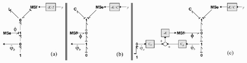
Figure 4. Suppression of dynamical elements in the bond graph model of the observer.
Step 5. Sum of the term Ky
The term Ky has to be summed to calculate the state
Figure 5. Sum of Ky: (a) in an I-element; (b) in a C-element.
Step 6. Sum of the term ϕ
The term ϕ is required to calculate
Lemma 1
The variables
Figure 6. Variable in the observer bond graph associated with: (a) I-element; (b) C-element.
Lemma 2
In the bond-graph model of the observer, when xb is associated with a C-element,
shows the addition of the term ϕ in the observer bond graph. In this figure, ϕ is added using a modulated flow source (because xb is associated with a C-element); according to Lemmas 1 and 2,
Figure 7. (a) Variable with an I-element; (b) Variable
with a C-element; (c) Addition of term ϕ.
If the designer does not want to use the bicausality concept to implement a reduced-order observer, another bond-graph approach for building reduced-order observer can be used (as proposed by Pichardo-Almarza et al. [Citation5]).
In that case, not using the bicausality concept in the implementation of the observer will have the following consequences:
| 1. | Calculation of | ||||
| 2. | The architecture of the observer model will be more complex because the order reduction is made substituting the dynamical elements associated with xa by modulated sources. | ||||
| 3. | Lemma 1 must be modified to identify | ||||
If the designer decides to implement a reduced-order observer, the graphical manipulations in the bond graph increase, but the estimation will have a smaller computational cost.
Once the designer has selected the type of observer, they are ready to calculate the gain from the observer bond-graph model. Next section proposes the technique used to design the observers.
3 Bond-graph approach to design the observer
The observer design is based on the pole placement techniques proposed by Rahmani et al. [Citation7] as in the approach proposed by Pichardo-Almarza et al. [Citation5, Citation6]. In this case, the characteristic polynomial of the full-order observer (P ( A−KC ) (s)) or the characteristic polynomial of the reduced observer
Theorem 4
The value of each coefficient of the characteristic polynomial P(A−KC) (s) or
Thus, the causal analysis to calculate K is made only with the family of causal cycles in the observer's bond graph.
Remark
The calculation of causal cycles in the observer model may be an arduous task if the designer does not have efficient bond-graph software. Ideally, the designer should dispose of bond-graph software that can calculate the observer gain applying a graphical analysis in the bond-graph model. Bond-graph software such as ARCHER [Citation12] or MS1 [Citation13] allows the causal loops and paths between variables in a model to be identified. These software suites are good tools for control analysis, but they need some improvements to be useful for the observer design.
In this paper, 20-sim® software [Citation14] was used as simulation tool. This software allows easy implementation of the observer bond graph, but symbolic calculations are not possible from the graphical model. For this reason, the authors had to use mathematical software (MATLAB®) to facilitate the symbolic and numerical calculations associated with observer gain.
4 Example
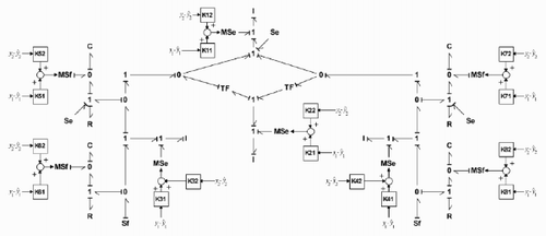
This example considers the 1/2 vehicle passive mechanical suspension () used by Dauphin-Tanguy et al. [Citation15]. The motions considered are heave and pitch. The disturbance inputs are road motion (on the left and right wheels), the gravity and the mass-transfer force due to braking or accelerating effects applied on the car's inertia centre G. shows the bond-graph model in the integral causality of the system. Only relative velocities are measurable, which are represented by Df-sensors in the BG model. These measures will be used to design the state observers for a future state feedback control law implementation.
Figure 8. Bicycle suspension in vertical motion: (a) physical model; (b) bond graph model.
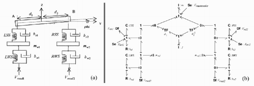
From , it is possible to define four states as accessible: pm, pJ, pmw1 and pmw2 because the I-elements Im, IJ, Imw1 and Imw2 have a direct causal path with a detector. As there are only two measurements, it is possible to define six different pairs of accessible state variables (xa ):
Step 1. Verification of the non-existence of redundant outputs.
In the model of , the detectors can be dualized without creating any causality conflict; thus, from Property 1: bg-rank[C] = 2. Thus, the measurements in the Df-sensors are non-redundant outputs.
Step 2. Verification of the structural observability
Applying the technique proposed by Sueur and Dauphin-Tanguy [Citation8], after assigning a preferred derivative causality on the model, it is possible to conclude that the model is structurally observable by these detectors.
4.1 Full-order observer
The construction of the full-order observer is based on procedure 2.1. Thus, only Step 3 should be applied to finish the construction.
Step 3
The term
Figure 9. Bond graph model of the full-order observer.
4.2 Design of the full-order observer
The poles of the observer have been selected slightly more rapid than the poles of the model:
From the observer bond-graph model (), it is possible to find hundreds of families of causal cycles associated with each polynomial coefficient. MATLAB® software has been used to calculate numerically the gain matrix of the observer. Then, with the desired poles, sd , the gain of the observer is:
4.3 Reduced-order observer
The construction of the reduced-order observer is based on the procedure 2.2. Then, step 3, 4, 5 and 6 can be applied.
Step 3. Selection of xa
As mentioned before, to build the reduced-order observer there are four states variables that can be defined as accessible: pm, pJ, pmw1 and pmw2 ; then, there exist six possible pairs of xa to build a reduced-order observer. In this example, only one observer is designed, considering pm and pJ as accessible state variables; then:
Step 3.1. Verification of rank (Ca ) = m
In the bond-graph model, the detectors are substituted by SS elements, and the causality of the dynamical elements associated with xa is changed to a bicausality (). This operation can be made in the BG-model, thus: bg-rank (Ca ) = m.
Figure 10. (a) Step 3: Verification of bg-rank (Ca ); (b) Step 4: Suppression of dynamical elements; (c) Step 5: Sum of the term Ky; (d) Step 6: Bond graph model of the reduced order observer.
Step 4. Suppression of the dynamical elements associated with xa
From the bond-graph model with bicausalities obtained in the previous step, the I-elements with bicausalities are substituted by 1-junctions ().
Step 5. Sum of the term Ky
The term Ky is added in each dynamical element (associated with xb ) with modulated sources as shown in .
Step 6. Sum of the term ϕ
The term ϕ is added with modulated sources. With this last operation, the observer model is complete (). In , the terms KCaij are the components of – KCa , and KCbij are the components of – KCb (according to Equationequation (16)).
4.4 Design of the reduced-order observer
The poles of the observer have been selected slightly more rapidly than the poles of the model:
In this case, hundreds of families of causal cycles are found, too. Again, MATLAB® software has been used to calculate the gain of the observer. Then, with the desired poles, sd , the gain of the observer is:
4.5 Simulations
For the simulations, the parameters have the following numerical values: m = 761 kg, mw 1 = mw 2 = 35 kg, bw 1 = bw 2 = 1000 Ns m−1, bs 1 = bs 2 = 1900 Ns m−1, d 1 = d 2 = 1.495 m k LSS = k RSS = 12 000 N m−1, k LWS = k RWS = 120,000 N m−1, J = 850 kgm−2.
The mass transfer, supposed to be due to a braking action, is modelled by the response of a first-order model 1 / (1 + 0.1s) to a pulse input (amplitude – 800 N, t 0 = 0.1 s, t 1 = 0.2 s). The observer behaviour is evaluated considering that there exist uncertainties in the vehicle mass; the mass was incremented up to 1000 kg (which might represent the mass of three additional passengers in the car).
shows the dynamics of absolute errors (for some state variables [x1 x2 x3 x4] T = [p mw 1 p mw 2 p LSS p LRS ] T ), and shows the relative estimation error in the steady state when both observers are used. These results show the sensitivity of the estimation error with respect to the variation in vehicle mass. When the parameters of the Luenberger observers are equal to the parameters of the original model the estimation error always converges to zero. However, the state estimation error does not always converge to zero if a Luenberger observer is used to estimate the states in linear uncertain systems [Citation16].
Figure 11. Estimation error: (a) full-order observer; (b) reduced-order observer.
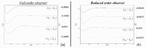
Table 1. Relative estimation error in steady state*.
Remark
When the bond-graph approach to build the reduced-order observer without bicausalities is applied in this example, the same K matrix is obtained, and the simulation results are equal to those shown in .
5 Conclusions
In this paper, two methods have been shown to build and design Luenberger observers. Although the full-order observers are simpler in their construction, the reduced-order observers represent a good estimator, since these yield a computational cost decrease. With the advantages of the bicausality concept, the bond-graph approach to build the reduced-order observers does not need an explicit calculation of Ca −1. The approaches shown in this paper represent a control tool for those developing a bond-graph model. The matrix calculations are substituted by causal manipulations applied in the observer bond graph.
Although, with the development of computers, the inversion of matrices is an operation that can be easily handled (even for relatively large matrices), besides saving on computational costs associated with matrix inversion, it is useful for a bond-graph modeller to have graphical control tools (based on bond graphs) for which state equations do not need to be written and which simplify the matrix calculations as soon as possible. Finally, the methods for designing linear observers shown in this paper would be less arduous if the graphical operations related to the calculation of the K matrix could be implemented directly in the existing bond-graph software.
References
References
- Luenberger , DG . 1964 . Observing the state of a linear system . IEEE Transactions on Military Electronics , MIL-8 : 74 – 80 .
- Gopinath , B . 1971 . On the control of multiple input – output systems . Bell System Technical Journal , 50 : 1063 – 1081 .
- Luenberger , D . 1966 . Observers for multivariable systems . IEEE Transactions on Automatic Control , 11 : 190 – 197 .
- Luenberger DG 1971 An introduction to observers. IEEE Transactions on Automatic Control, AC-16 596 602
- Pichardo-Almarza C Rahmani A Dauphin-Tanguy G Delgado M 2003 Paper presented at the Proceedings of 4th MATHMOD, Fourth International Symposium on Mathematical Modelling
- Pichardo-Almarza C Rahmani A Dauphin-Tanguy G Delgado M 2003 Paper presented at the Proceedings of ECC'2003, European Control Conference
- Rahmani , A , Sueur , C and Dauphin-Tanguy , G . 1994 . Pole assigment for systems modelled by bond graph . Journal of the Franklin Institute , 331 : 299 – 312 .
- Sueur , C and Dauphin-Tanguy , G . 1991 . Bond graph approach for structural analysis of MIMO linear systems . Journal of the Franklin Institute , 328 : 55 – 70 .
- Karnopp , D . 1979 . Bond graphs in control: physical state variables and observers . Journal of The Franklin Institute , 308 : 221 – 234 .
- Gawthrop P 1995 Paper presented at the Proceedings of the 1995 International Conference on Bond Graph Modelling and Simulation: ICBGM'95 pp. 83 – 88
- Ngwompo , F , Scavarda , S and Thomasset , D . 1996 . Inversion of Linear Time-invariant Systems Modelled by Bond Graph . Journal of the Franklin Institute , 333 : 157 – 174 .
- Azmani A Dauphin-Tanguy G 1992 In: P.C. Breedveld and G. Dauphin-Tanguy (Eds) Bond Graphs for Engineers pp. 263 – 277 Amsterdam IMACS, North Holland
- LorSim Available online at: http://www.lorsim.be (accessed 12 March 2004)
- Controllab Products 1998 20-sim for Microsoft Windows version 2.3 Available online at: http://www.20sim.com (accessed 1 February 2004)
- Dauphin-Tanguy , G , Rahmani , A and Sueur , C . 1999 . Bond graph aided design of controlled systems . Simulation Practice and Theory , 7 : 493 – 513 .
- Schreier G 1997 Estimation de l'état de systèmes incertains Thèse de l'Institut National Polytechnique de Lorraine