Abstract
A hybrid distributed parameter model of a heating system for domestic hot water is presented in this paper. This heating system comprises a condensing boiler (burner), a counter current heat exchanger, and a so-called stratified storage tank which is the state of the art domestic hot water storage unit. The paper presents the model for the different operational modes of the plant which are described by a finite state automaton representing the discrete-event dynamics and driving the underlying continuous-time dynamics of the storage tank, the heat exchanger, and the burner. These interconnected components are modelled by a system of six coupled, quasi-linear partial differential equations (PDEs) comprising diffusion-, convection-, and source terms. In order to perform numerical simulations, the set of PDEs is spatially discretized using the method of lines. Thereby, the influence of various discretization schemes on the temporal evolution of the traveling temperature profiles in the single components is investigated. A high resolution slope limiter scheme for the stratified storage tank and a higher order up–/downwind scheme for the heat exchanger and the burner are found to be an appropriate choice for the spatial discretization of the model equations in order to adequately cover the plant dynamics. Simulation results fortify the effectiveness of the chosen discretization schemes and show the excellent performance of the suggested model representing the measurement data.
1. Introduction
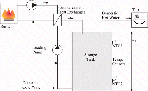
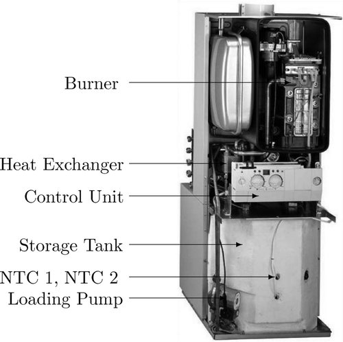
The use of storage tanks for domestic hot water in contemporary heating systems, as shown in , has proven great potential to save energy and increase comfort and availability. For solar heating systems, it is even indispensable, since in most cases there is a significant time gap between energy gain and consumption. Although storage of hot water is common practice in most households, the efficiency of ordinary storage systems is not satisfactory. Therefore, in the heating systems community, the state-of-the-art system for domestic hot water storage is the so-called stratified storage tank Citation1. In general, the fluid in the storage vessel has a certain temperature profile and thus a density gradient which assures the physical principle of stratification. To maintain this stratification, the storage tank in is driven with relatively low mass flows and equipped with baffle plates to ensure that the mixing and excitation of agitation flows in the in- and outflow regions of the tank are minimized. Due to the characteristic stratification of the water in the tank, i.e. hot water at the top part and cold water at the bottom part, domestic hot water (e.g. for shower, bath, kitchen) is always taken from the uppermost fluid layer. During tapping, equal amounts of cold fluid are introduced at the very bottom of the tank such that the vessel is always entirely filled with water. During loading, the storage tank is connected to the secondary side of a counter current heat exchanger and filled with the desired amount of hot water. Thereby, cold water is pumped from the bottom part over the heat exchanger and introduced back up into the top part of the tank. To feed the corresponding primary side with hot water, the heat exchanger is connected to a condensing boiler, referred to as the burner. The interconnection of the components of interest, i.e. burner, heat exchanger, and storage tank, can be inferred from . The system considered here is referred to as the Cerasmart Module and commercially available from Robert Bosch GmbH.
Figure 1. Heating unit with stratified storage tank, control unit, loading pump, burner, counter current heat exchanger, and temperature sensors (NTC 1 and NTC 2).
The dynamics of the plant is characterized by discrete-time events due to e.g. tapping or loading events as well as continuous time-varying spatial temperature profiles, which occur in the storage tank, the heat exchanger, and the burner. These components are represented by the respective distributed parameter models which are then coupled according to the flowsheet in . In detail, the models are given as a diffusion–convection system (DCS) with heat loss to the ambiance for the storage tank and as two counter current transport systems with heat exchange between the primary and secondary side for the heat exchanger and the burner. Thus, the entire model consists of a finite state automaton interacting with a continuous-time model of six underlying coupled quasi-linear partial differential equations. Consequently, the entire plant can be interpreted as a hybrid distributed parameter system Citation2.
Due to the rapid increase of the cost of energy, consumers require that process control schemes operate the plant in such a manner that energy consumption is minimized. However, today's standard is that the loading cycle is driven by a two-point controller that activates the loading pump and the burner if a predefined temperature threshold at the temperature sensor NTC1 is detected and correspondingly stops the loading after detecting a respective temperature threshold at NTC2. To develop a process control system which minimizes the consumed energy of the heating system, the set-up of a model-based process control scheme Citation3 is mandatory. Even though complex 3D finite element models exist for similar applications Citation4, the contribution of this paper is to provide a reduced-order model of the plant which is suitable for the development of a process control scheme for energy efficient, optimal loading of the storage tank. The tasks therefore are the design of a state observer Citation5, a control algorithm based e.g. on a flatness approach Citation6,Citation7, or on the method of characteristics Citation8,Citation9 and a dynamic real-time optimization scheme for the design of an economically optimal loading strategy Citation10.
The first part of the paper outlines the derivation of the hybrid plant model. Here, the finite state automaton with its five discrete states and its corresponding transitions is presented. Furthermore, the partial differential equations (PDEs) for the storage tank, the heat exchanger and the burner are derived. To perform numerical simulations, the spatial discretization of the PDEs is investigated in the second part of the paper. Thereby, the temporal evolution of the traveling temperature profiles in dependence of the discretization approach for the convection terms is analysed. For the tank model, a finite volume approach switching between an up – and a downwind scheme in dependence of the flow direction is compared to a switching high resolution slope limiter scheme. For the heat exchanger and the burner, a finite volume first order up- and downwind approach is compared to respective third- and fourth-order discretization approaches. In the last part of the paper, the suggested plant model is identified and compared to measurement data.
2 Hybrid plant model
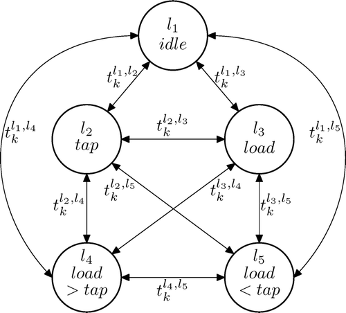
The discrete plant dynamics is characterized by switching events due to tapping and loading, which drive the underlying dynamical behaviour of the heat exchanger, the burner, and the storage tank Citation11. The discrete-event dynamics is fully described by a finite state automaton of five discrete states and their respective transitions. These states represent the operational modes of the plant and are distinguished as follows: idle state, loading state, tapping state, and the combined state of tapping and loading. Thereby, the operational mode where tapping and loading occurs simultaneously has to be divided into two discrete states depending on the resulting direction of the plug flow in the tank. The underlying continuous-time dynamics is characterized by time-varying spatial temperature profiles in the storage tank, the heat exchanger, and the burner. These components are modelled by six quasi-linear PDEs for the six state variables, namely the temperature T(z,t) in the storage tank, the primary and secondary side temperatures Θpr(x,t) and Θsec(x,t) in the heat exchanger, and the primary side, wall, and secondary side temperatures τpr(ζ, t), τw(ζ, t), and τsec(ζ, t) in the burner. These temperature profiles depend on the spatial coordinates z, x, and ζ as well as on time t. In the subsequent section (2.1), the finite state automaton is introduced, followed by a description of the distributed energy balances for the heat exchanger, the burner, and the storage tank in Sections 2.2–2.4.
2.1 Discrete state automaton
A finite state automaton can be denoted as a labelled transition system, described by a triple (L,A,E), where L is the finite state space, A is a finite set called alphabet, and E is the corresponding transition rule Citation2. A sequence (l 0, a 0, l 1, a 1, … , l N−1, a N−1, l N ) with (l m , a m , l m+1) ∈ E for m = 1, 2, … is called a trajectory on the state space Citation2. Using this notation, the state space of the finite state automaton of the storage tank is given by
The graph of the resulting finite state automaton is depicted in . Note that depending on the tapping and loading mass flows during the states l
4 and l
5, the resulting plug flow in the storage tank is either positive, i.e. directed from top to bottom, or negative, i.e. from bottom to top. For an appropriate choice of the numerical approach, the separation of these two states is of great relevance. The alphabet of the finite state automaton Citation2 is labelled by implicitly caused discrete switching times (due to a tapping or loading event) denoting the transitions from one state l
m
to another state l
n
, i.e.
Figure 3. Graph of the finite state automaton describing the operational modes of the plant. For the sake of simplicity, transitions are labeled only unidirectionally, i.e. for each there exists a corresponding transition
.
With EquationEquations (1) and Equation(2)
, the general transition rule can be derived to be
Citation2, i.e.
is an example for a possible trajectory on the discrete state space L in dependence of the events occurring.
2.2 Distributed parameter model of the heat exchanger
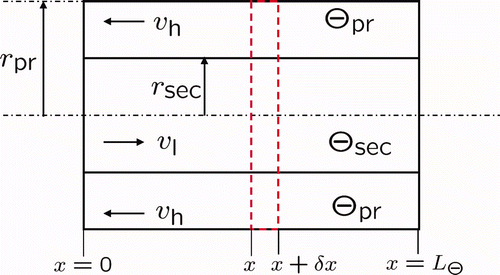
The counter current heat exchanger is modelled by a set of two coupled first-order partial differential equations Citation8,Citation12, each comprising a convection and a source term accounting for the heat exchange between the primary and the secondary side of the system. Therefore, a pipe-in-pipe system with length L Θ is used to model the primary (outer pipe) and the secondary side (inner pipe) of the heat exchanger (see ). The separating wall between the two pipes is assumed to be negligibly thin, such that heat conduction along and through the wall is neglected. Setting up the energy balance for an infinitesimally small volume element with length δx and applying a Taylor series expansion for the element bound at x + δx yields the model equations of the heat exchanger for δx → 0. The resulting equation for the primary side is
Figure 4. Sketch of the counter current heat exchanger with primary and secondary side temperature profiles Θpr(x,t) and Θsec(x,t) as well as the respective flow velocities v h(t) and v l(t).
Accordingly, the energy balance of the secondary side is given by
As shown in Section 4, the heat transfer coefficient α between the two heat exchanger pipes in EquationEquations (3) and Equation(4)
is obtained by minimizing the least squares error between model and measurement data. Therefore, the geometry of the pipes is chosen to match the transfer area and the primary and secondary side volumes of the heat exchanger. The Dirichlet boundary condition (BC) at x = 0 reads as
The initial conditions (ICs) in the pipes are
Here, , which means that the heat exchanger model is activated during the discrete states l
3, l
4 and l
5.
2.3 Distributed parameter model of the burner
This section first summarizes the operating principle of the condensing boiler, followed by the presentation of the distributed parameter model of the burner. A fan feeds the combustion chamber of the burner with an air mass flow proportional to the fan speed (n
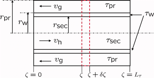
F(t)) (see ). The respective gas mass flow is adjusted by a mechanical λ – control, which guarantees optimal combustion in the burner. Here, the combustion chamber is referred to as the primary side of the burner. The burning gas is then used to heat up the water in the secondary side of the burner. The model of the burner is therefore set up in accordance to the counter current principle used for the heat exchanger in Section 2.2. Due to the thickness of the walls in the burner, i.e. the separating wall between the primary and secondary side, the structure in EquationEquations (3) and Equation(4)
has to be extended by an additional PDE for the wall. As depicted in the sketch in , the actual model of the burner is split up into two parts. The first part consists of two algebraic relations to determine the flow velocity v
g(t) and the primary side feed-flow temperature
as a function of the fan speed n
F(t) according to
Figure 5. Setup of the burner composed of the fan with the fan speed n F and the heat exchanging unit (pipe system) with the primary and secondary side temperatures τpr(ζ, t) and τsec(ζ, t) as well as the respective flow velocities v g(t) and v h(t).

The parameters v
g,max and p
1, … ,4 are determined by minimizing the least squares error between simulations and measurement data, i.e. all effects of combustion are summarized in . EquationEquations (8)
and Equation(9)
are employed to calculate the respective primary side inputs of the second part of the burner model, i.e. the dynamical part (the pipe system) which can be interpreted as a counter current heat exchanger with a dividing wall, as depicted in . Setting up the energy balance for the volume element δζ and following the procedure in Section 2.2 yields the model equations for the primary side,
Figure 6. Sketch of the heat exchanging part of the burner with the primary side, wall, and secondary side temperatures τpr, τw, and τsec as well as the respective flow velocities v g(t) and v h(t).
The boundary conditions at the inlets of the primary and secondary side are
The ICs read as
In the sequel, the IC of the wall τw(ζ, ) is chosen to be the arithmetic mean between the temperatures of the primary and secondary side. Note that due to the significant length of the pipe system in the burner, heat conduction within the wall is negligible. The coefficients of the exchange terms in EquationEquations (10)
–Equation
Equation(12)
, i.e. γpr, γsec, q
pr and q
sec, are also obtained by an optimization-based parameter identification. The optimization result is presented in Section (4).
2.4 Distributed parameter model of the stratified storage tank
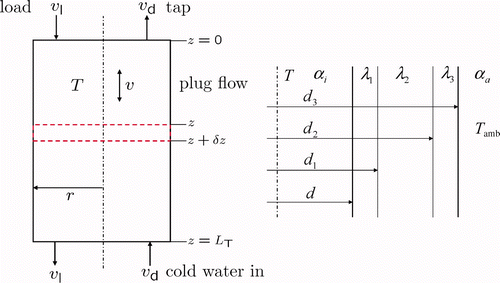
The governing model equations of the storage tank can be obtained following the derivation of the heat exchanger and burner equations. Due to the large diameter of the storage vessel, flow velocities are significantly smaller than in the heat exchanger. Therefore, it is necessary to extend the partial differential equation by a conductive component which is set up according to Fourier's heat conduction Citation13. Further, the BCs have to be expanded to Cauchy BCs to model the heat loss through the ceiling and bottom of the storage tank. The resulting temperature distribution in the stratified storage tank can be described by the following PDE with BCs and a respective IC according to
Figure 7. Left: labeled scheme of the storage tank with respective in- and outflow velocities v l,d(t) and the resulting plug flow velocity v(t). Right: cross section of the storage wall with corresponding diameters d m , m = 1,2,3, heat conduction coefficients λ m , and heat transfer coefficients α n , n∈{i, a}.
The general hybrid I/O-behaviour of the plant is on the one hand dominated by uncertain tapping events driven by the consumer and on the other hand based on the loading events initiated by a respective process control strategy. These events determine the in- and outflows of the storage tank. Consequently, the model equations depend on the corresponding discrete states in L and may furthermore be simplified significantly. This concerns especially the BCs (16)–(17) of the stratified storage tank. The reduction for the relevant discrete states in L is summarized below and can be easily incorporated in the respective equations according to
2.4.1 Model parameters
In the sequel, the derivation of the heat transfer coefficient of the storage tank is outlined. The derivation of the respective coefficient is hereby based on physical relations. As shown in , the storage wall consists of three material layers with different heat conductivity. The coefficient k w is therefore composed of the convective heat transfer in water and air, the heat conduction in each of the three wall layers and the radiative heat at the outside wall of the tank. According to Citation13, the equation for the heat transfer coefficient k w of a wall with various layers and an inner wall diameter d is given by
The radiative heat transfer is governed by
3 Numerical simulation of the hybrid plant model
This section illustrates the numerical setup of the hybrid plant model for the discrete states l 2 – l 5. Due to the hyperbolic nature of the PDEs during tapping and loading, the discretization of the convection terms plays a major role for numerical simulation studies. Hence, different discretization schemes are investigated in terms of accuracy and resulting model dimension of the discretized lumped model. The first part of this section considers the discretization of the storage tank model. Here, the reconstruction of sharp spatial transitions, as they are present in the stratified storage tank, is of great interest. Therefore, a finite volume up- and downwind scheme in dependence of the flow direction as well as a high resolution scheme, a so-called slope limiter scheme Citation17, are investigated. The second part of the section gives a brief discussion on the discretization of the heat exchanger and burner model where up- and downwind schemes of different approximation orders are used.
3.1 Discretization of the storage tank equation
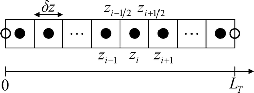
A method of lines (MOL) approach Citation18 is employed for the spatial discretization of the model EquationEquation (15). The temperature distribution in z – direction is approximated by clustering the spatial domain in N
T
finite volumes, see . The centre of the i‐th volume is denoted by z
i
and the volume bounds as
, respectively. Integration of (15) over a control volume yields
For the evaluation of the integral (23), certain assumptions are made. Choosing the coefficients λw, ρ, c, k w and the temperature T to be constant within the interval z ∈ [z i−1/2, z i+1/2] and with δz = z i+1/2 – z i−1/2 = const, entails the discretized version of the storage PDE (15), i.e.
As mentioned before, special effort has to be spent to find an appropriate approximation of the convective terms. The various approaches mentioned previously are generally represented by the following substitution for the control volume bounds T i±1/2 according to
where Φ denotes the so-called limiter function Citation17,Citation19. Consequently, for v > 0, the spatially discretized PDE (15) results as
In EquationEquation (29), the well-known upwind scheme is obtained by setting the limiter function Φ
i+1/2 = Φ
i−1/2 = 0, whereas the corresponding downwind scheme can be obtained for Φ
i+1/2 = Φ
i−1/2 = 2 Citation18. Since the plug flow velocity in the storage tank changes sign, Gibb's phenomenon Citation20 has to be avoided by employing the upwind scheme for v > 0 and the downwind scheme for v < 0, i.e. the choice of the numerical scheme depends on the flow direction and therefore also on the discrete state of the finite state automaton. The so-called central difference scheme (CDS) is obtained by setting Φ
i+1/2 = Φ
i−1/2 = 1. The performance of the previously named approaches changes significantly for different spatial resolutions, especially for the upwind scheme. However, due to numerical diffusion, this approach is not feasible for the reconstruction of sharp spatial transitions. As opposed to the upwind scheme, the CDS perfectly reconstructs sharp transitions of the spatial profile. Unfortunately, this discretization method leads to the occurrence of spatial oscillations and therefore to an unsatisfactory result. The idea of a high resolution slope limiter scheme is now to combine the benefits of the previously named methods, i.e. oscillation-free reconstruction of sharp transitions. This can be realized by defining Φ as a nonlinear function of the so-called smoothness
, which in turn is defined as
3.2 Discretization of the heat exchanger and burner equations
Similar to the spatial discretization of the stratified storage tank, a MOL approach is used for the discretization of the heat exchanger and the burner. Due to the similarity of the system structure and the occurring spatial temperature profiles in the heat exchanger and the burner, the subsequent considerations are outlined on the basis of the heat exchanger model in EquationEquations (3) and Equation(4)
but are then used for the discretization of both the heat exchanger and the burner. The following three discretization approaches adopted from Citation18 are investigated:
Hereby, a classical first-order up/downwind scheme is used for the calculation of the boundary values in EquationEquations (33) and Equation(34)
, while the forth-order approach is based on a special higher order up- and downwind approximation of the boundary conditions (referred to as “Subroutine DSS020” in Citation18).
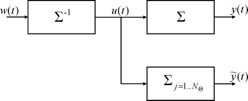
To classify the transient and stationary performance of the different discretization orders, a respective reference trajectory has to be specified. This can be done using an analytical solution of the PDE. However, the analytical solution is generally not known or difficult to evaluate. For the special case of the heat exchanger, the analytical solution includes infinite sums of Bessel functions Citation22. Their evaluation is costly and only possible to a certain accuracy. Hence, an alternative approach is suggested for cases, where an exact inversion of the PDE considered is available Citation6. The procedure is then as follows: a desired trajectory w(t) which is dynamically feasible on one hand and which covers the transient and the stationary behaviour of the process on the other hand has to be chosen. With the use of an exact inversion Σ−1 of the system Σ, a feedforward control u(t) can be calculated, i.e. u(t) = Σ−1
w(t) Citation15. Then w(t) can be used as the respective reference trajectory when the calculated feedforward control is applied to the system Σ, i.e. y(t) = Σu(t) = ΣΣ−1
w(t) and therefore (see ). Substituting the distributed system Σ by its discretized counterpart
yields the distorted output trajectory
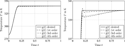
, which is then used for the assessment of the discretization scheme. For the explicit case of the heat exchanger model, the performance is depicted in . The inversion of the heat exchanger model is hereby obtained according to the methodology described in Citation6. further shows that the minimum variation between the desired and distorted trajectory can be obtained using the 3rd order discretization scheme. This means that for the considered range of operation, the different approximation of the boundary values in EquationEquation (35)
leads to an overall degradation of the 4th order scheme compared to the 1st and 3rd order approach. Hence, the 3rd order scheme according to EquationEquation (34)
is used for the spatial discretization of both, the heat exchanger and the burner model.
3.3 Simulation results of the hybrid plant model
The discretized plant model, i.e. burner, heat exchanger, and stratified storage tank, is implemented in a MATLAB/SIMULINK environment Citation23, allowing for the numerical simulation of the plant and the examination of its hybrid behaviour. The implementation is set up in a flexible manner, such that all types of scenarios which can possibly occur in the course of the plant operation may be studied.
Footnote1
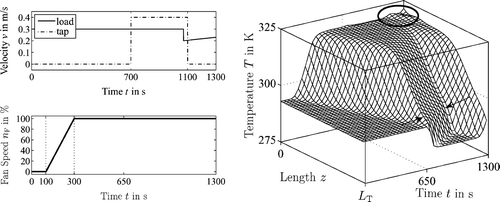
shows the simulation result of the temperature profile T(z,t) in the storage tank for various variations of the flow velocities v
l,d and the fan speed n
F. Hereby, the simulation scenario covers the following effects: at t = 0 s the storage tank has an initial temperature profile with T(z,0) = 293 K. During the time interval 0 s ≤ t < 700 s, the storage tank is operated in the discrete state l
3 with a ramp-like rise of the fan speed n
F for 100 s ≤ t ≤ 300 s and a loading velocity v
l = 0.3 m/s, according to the solid lines in . It can be seen that due to the wall and the circular setup of the heat exchanger and the burner, the ramp-like increase of the fan speed results in a smooth rise of the feed flow temperature at z = 0. Due to the tapping event occurring during the time interval 700 s ≤ t ≤ 1100 s, cold water is introduced at z = L
T
. Note that in this case, the discrete state automaton is in state l
5, where the tapping flow velocity v
d exceeds the loading flow velocity v
l, i.e. the plug flow reverses and the tank discharges. Hereby, the transitions between the discrete states l
3 and l
5 are denoted by the arrows in . At t = 1100 s, the state automaton switches back to the state l
3 and the storage tank gets refilled. For this latter case, the variation of the loading velocity for t ≥ 1070 s is chosen such that the variation of the feed flow temperature
at the top of the storage tank is kept inside a certain band. The respective region is marked by a circle in .
4 Model identification
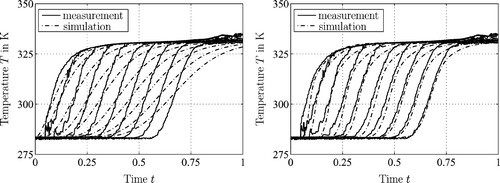
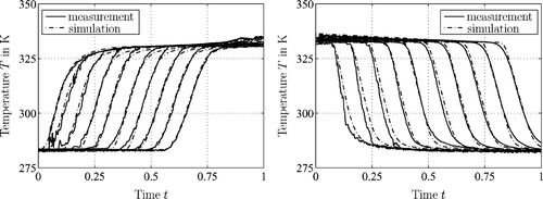
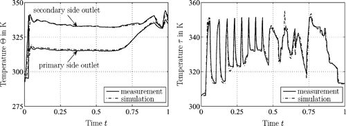
In this section, the hybrid plant model is identified via least squares optimization using measurement data obtained for the operational modes l 2 and l 3. The datasets of the heat exchanger, the burner, and the storage tank are presented and compared to the respective simulation results. Thereby, the discretization scheme and the required number of grid points for the storage tank model are furthermore discussed and determined. It shall be emphasized that the subsequent plots rely on a normalized time scale. shows the identification results for the heat exchanger and the burner. It can be inferred from the plots that the heat exchanger and the burner model are feasible to track the measurement data very well for both, the stationary and the transient regions. To identify the storage tank model, ten equidistantly distributed thermocouples are attached from top to bottom on the inside wall of the tank. The numerical simulations of the upwind scheme () and the slope limiter scheme using a Superbee limiter () are compared to corresponding measurement data. In the case of the upwind scheme with a spatial discretization of 20 nodes, the model reconstructs the measured values very poorly. However, by increasing the spatial discretization up to 300 nodes, a far better fit can be achieved. Even though better results are attained by increasing the spatial resolution of the upwind scheme, numerical diffusion is still present, see . As illustrated in , the slope limiter scheme bears significant improvements for the loading scenario. It is furthermore shown that applying the high resolution scheme with Superbee limiter to the tapping state where hot water is taken from an entirely filled storage cell, the measured and simulated values agree very well. Note that for the high resolution scheme, a spatial discretization of only 21 grid nodes is sufficient.
Figure 12. Left: plot of the measured and simulated outlet temperatures of the primary and secondary side of the counter current heat exchanger. Right: measured and simulated temperature profiles at the secondary outlet of the condensing boiler.
5 Conclusion and outlook
In this paper, the derivation of a hybrid model of a domestic heating system comprising a condensing boiler (burner), a heat exchanger, and a stratified storage tank is outlined. Thereby, the model parameters of the burner and the heat exchanger are obtained by minimizing the least squares error between the simulation results and measurement data. The derivation of the storage tank parameters are based on physical considerations. To perform numerical simulations, different discretization schemes according to the method of lines approach are investigated in terms of feasibility and numerical performance. It is hereby shown that for the storage tank, where sharp spatial temperature gradients are present, the high resolution slope limiter scheme with Superbee limiter outperformed the up-/downwind scheme and the CDS. It is further found that a third-order up-/downwind scheme is well suited for the discretization of the heat exchanger and the burner. The good agreement between the measurement data and simulation results for stationary and transient scenarios justifies the suitability of the suggested models of the burner, the heat exchanger, and the stratified storage tank. Consequently, this model can be used to study the challenging task of advanced process control design for domestic heating systems with stratified storage tank as an example for a hybrid distributed parameter system Citation24. Future research is necessary to model the free convection phenomena occurring in the course of the discrete state l 2 of cooling.
Notes
Revised and expanded version of a paper presented at the 5th Vienna International Conference on Mathematical Modelling (5th Mathmod), Vienna, Austria, 2006.
1. The MATLAB - ode23tb solver is used for the time-integration of the discretized PDEs.
References
- Dincer , I. and Rosen , M. A. 2002 . Thermal Energy Storage - Systems and Applications , New York : John Wiley .
- van der Schaft , A. and Schumacher , H. 2000 . An Introduction to Hybrid Dynamical Systems , Berlin : Springer Verlag .
- Ray , W. H. 1980 . Advanced Process Control , New York : McGraw‐Hill Education .
- Lin , W. and Armfield , S. W. 1999 . Direct simulation of natural convection cooling in a vertical circular cylinder . Int. J. Heat Mass Trans. , 42 : 4117 – 4130 .
- Kreuzinger , T. , Bitzer , M. and Marquardt , W. 2006 . Design of a quasi‐linear distributed state observer and parameter estimator for a stratified storage tank . Proceedings of the 2006 IEEE International Conference on Control Applications . 2006 , Munich, Germany. pp. 680 – 685 .
- Kreuzinger , T. , King , F. A. , Bitzer , M. and Marquardt , W. Feedforward boundary control of linear distributed parameter systems using a numerical inverse Laplace transform . preprints of the 3rd IFAC Symposium on System, Structure and Control SSSC07, Foz do Iguassu, Brazil, 17–19 October 2007
- Rudolph , J. 2000 . Randsteuerung von Wärmetauschern mit örtlich verteilten Parametern: ein flachheitsbasierter Zugang . at-Automatisierungstechnik , 48 : 399 – 406 .
- Rhee , H.-K. , Aris , R. and Amundson , N. R. 1986 . First-Order Partial Differential Equations , Vol. I , NJ, , USA : Prentice-Hall, Englewood Cliffs .
- Huilan , Shang . 2002 . Characteristic-based Control of Distributed Parameter Systems Ph.D. thesis, Department of Chemical and Materials Engineering, University of Alberta
- Busch , J. , Oldenburg , J. , Santos , M. , Cruse , A. and Marquardt , W. 2007 . Dynamic predictive scheduling of operational strategies for continuous processes using mixed – logic dynamic optimization . Comput. Chem. Eng. , 31 : 574 – 587 .
- Kreuzinger , T. , Bitzer , M. and Marquardt , W. Hybrid modeling of a stratified storage tank . Proceedings of the 5th Vienna Symposium on Mathematical Modelling (5th Mathmod) . Vienna, Austria. Edited by: Troch , I. and Breitenecker , F. Vol. 2 , pp. 1 – 10 .
- Evans , L. C. 2002 . Partial Differential Equations , USA : American Mathematical Society, Rhode Island .
- Bird , R. B. , Stewart , W. E. and Lightfoot , E. N. 1960 . Transport Phenomena , New York, , USA : John Wiley .
- Probstein , R. F. 2003 . Physiochemical Hydrodynamics , New York : Wiley Interscience .
- Glück , B. 1989 . Wärmeübertragung - Wärmeabgabe von Raumheizflächen und Rohren , Berlin, , Germany : VEB Verlag für Bauwesen .
- VDI Gesellschaft Verfahrenstechnik und Chemieingenieurwesen VDI – Wärmeatlas VDI Verlag GmbH Düsseldorf 1991
- Roe , P. L. 1985 . Some contributions to the modelling of discontinuous flows . Lecture Notes Appl. Math. , 22 : 163 – 193 .
- Schiesser , W. E. 1991 . The Numerical Method of Lines Integration of Partial Differential Equations , San Diego : Academic Press .
- LeVeque , R. 1992 . Numerical Methods for Conservation Laws , Basel : Birkhäuser Verlag .
- Patankar , S. V. 1980 . Numerical Heat Transfer and Fluid Flow , New York : McGraw-Hill .
- Köhler , R. 2002 . Preprocessing Tool for Method-of-Lines Discretization of Process Models in the Simulation Environment DIVA , Fortschritt-Berichte Reihe 20 Nr. 357, VDI-Verlag Düsseldorf .
- Jawson , M. A. and Smith , W. 1954 . Countercurrent transfer processes in the non-steady state . Proceedings of the Royal Society, vol. 226 . 1954 .
- The MathWorks Inc. Matlab Documentation August 2005 Matlab 7.1, Release 14
- Christofides , P. D. 2001 . Control of nonlinear distributed process systems: recent developments and challenges . AIChE J. , 47 : 514 – 518 .
