Abstract
Objective: The objectives of this study are to propose a new instrumentation technique for measuring cervical spine kinematics, validate it, and apply the instrumentation technique to postmortem human subjects (PMHS) in rear impact sled tests so that cervical motions can be investigated.
Methods: First, a new instrumentation and dissection technique is proposed in which instrumentation (3 accelerometers, 3 angular rate sensors) capable of measuring the detailed intervertebral kinematics are installed on the anterior aspects of each vertebral body with minimal muscular damage. The instrumentation was validated by conducting 10 km/h rear impact tests with 2 PMHS in a rigid rolling chair. After this validation, a total of 14 sled tests using 8 male PMHS (175 ± 6.9 cm stature and 78.4 ± 7.7 kg weight) were conducted in 2 moderate-speed rear impacts (8.5 g, 17 km/h; 10.5 g, 24 km/h). A current rear impact dummy, BioRID II, was also tested under the same condition with an angular rate sensor installed on each of the cervical vertebrae so that rotations of the cervical spine of the BioRID II could be compared to those measured from the PMHS. The National Highway Traffic Safety Administration (NHTSA) biofidelity ranking system was used for quantitative analysis of the BioRID II cervical spine biofidelity.
Results: Results show that the BioRID II exhibited comparable rotations to the PMHS in the 17 km/h test, but the vertebrae in the lower cervical spine (C5–C7) of the BioRID II showed less rearward rotation than the PMHS. For the 24 km/h test, the vertebrae in the cervical spine of the BioRID II exhibited less rearward rotation than the PMHS at all levels (C2–C7). The average biofidelity score for C2 through C7 was 1.02 for the 17 km/h test, and 2.27 for the 24 km/h test.
Conclusions: These results reflect the fact that the fully articulated spine of the BioRID II was designed and tuned to model low speed rear impacts. The intervertebral rotations for both the PMHS and the BioRID II were primarily relative flexion rotations even though the cervical vertebrae rotated rearward with respect to the global coordinate system.
Supplemental materials are available for this article. Go to the publisher's online edition of Traffic Injury Prevention to view the supplemental file.
Introduction
Claims of cervical spine injuries in rear impact collisions (e.g., whiplash) are common and result in enormous societal cost, with estimates on the order of $8.0 billion annually (National Highway Traffic Safety Administration [NHTSA] Citation2004). Numerous studies have investigated occupant biomechanics and cervical spine injury mechanisms during simulated rear impacts utilizing volunteers (Croft and Philippens Citation2007; Geigl et al. Citation1994; Mertz and Patrick Citation1967; Ono et al. Citation1997; Siegmund et al. Citation1997; Van den Kroonenberg et al. Citation1998) and/or postmortem human subjects (PMHS; Bertholon et al. Citation2000; Deng et al. Citation2000; Geigl et al. Citation1994; Hu et al. Citation1977; Kallieris et al. Citation1996; Kang et al. Citation2012; Mertz and Patrick Citation1967; Philippens et al. Citation2000; Yoganandan et al. Citation2000). Other studies have investigated intervertebral kinematics using whole cervical spine specimens on a mini-sled (Panjabi et al. Citation1998, Citation2005; Stemper et al. Citation2003; Tencer et al. Citation2004). Despite the fact that rear impact events have been studied extensively, there is no consensus as to the exact mechanism of injury or most relevant injury criterion. Proposed soft tissue injury sites vary and include facet joints, capsular ligaments, and intervertebral discs. Though the precise location of injury is debated in the literature (Bertholon et al. Citation2000; Croft and Philippens Citation2007; Deng et al. Citation2000; Geigl et al. Citation1994; Kang et al. Citation2012; Mertz and Patrick Citation1967; Ono et al. Citation1997; Philippens et al. Citation2000; Siegmund et al. Citation1997; Van den Kroonenberg et al. Citation1998; Yoganandan et al. Citation2000), there is reasonably good agreement that the injuries occur due to relative rotation and displacement between adjacent vertebrae that exceeds the physiological range of motion (ROM; Deng et al. Citation2000; Ono et al. Citation1997; Panjabi et al. Citation1998, Citation2005; Stemper et al. Citation2003; Sundararajan et al. Citation2004; Tencer et al. Citation2004; White et al. Citation2009). This illustrates the importance of being able to measure the detailed intervertebral kinematics of the cervical spine during a rear impact event.
A few studies have captured the detailed intervertebral kinematics using a high speed X-ray imaging system (Deng et al. Citation2000; Ono et al. Citation1997; Sundararajan et al. Citation2004; White et al. Citation2009). Although this provides a minimally invasive and visually appealing anatomic view of the cervical spine kinematics in fully intact PMHS or volunteers, it is limited by a small field of view (e.g., 25 × 25 cm2 in Ono et al. [Citation1997] and 30 × 30 cm2 in Deng et al. [Citation2000]) that typically cannot visualize the entire cervical spine (i.e., only C2–C6) and for some test conditions is unable to capture the cervical motion during the entire event (the White et al. [Citation2009] study and the Sundararajan et al. [Citation2004] study both reported that the maximum rotation of the vertebrae occurred after leaving the field of view in their tests). Consequently, using high-speed X-ray to measure rear impact cervical kinematics is limited to low-speed tests and/or using a rigid, nonyielding seat back.
Intervertebral kinematics have also been studied by mounting isolated cervical spine specimens to a mini-sled, applying a horizontal acceleration, and obtaining the kinematics using high-speed video (Panjabi et al. Citation1998, Citation2005; Stemper et al. Citation2003; Tencer et al. Citation2004). In these studies (with the exception of Stemper et al. [Citation2003]) the muscles and skin were removed from the spine specimens so that only the ligamentous spine was evaluated, although Panjabi et al.'s (Citation1998, Citation2005) studies did incorporate spring-cable muscle force replicators. Obtaining the intervertebral kinematics using isolated spine specimens provides a detailed anatomical view of the cervical kinematics and does not limit the severity of potential test conditions, but the acquisition rate for high-speed video is somewhat limited (typically 1000 f/s), particularly when calculating velocity and acceleration of the vertebrae. In addition, because the upper thoracic spine (i.e., lower end of the specimen) must be fixed, the kinematic effects due to rotation of the thoracic spine (e.g., T1) cannot be accounted for, and thoracic interaction with the automotive seat back along with the kinematic effects of ramping, which affects the kinematics of the entire spine (lumbar to cervical), cannot be analyzed.
In order to address some of the limitations of the isolated cervical spine specimen studies, Ivancic et al. (Citation2009) modified the BioRID II, an anthropometric test device (ATD) for rear impact, by replacing the ATD neck with cadaveric cervical spine specimens. This improvement allows for the effects of thoracic interaction with the seat back and ramping to be incorporated in the kinematics of cervical spine specimens. However, because an anthropometric surrogate head (4.2 kg mass; 0.0244 kg-m2 mass moment of inertia) was mounted on the top of each cervical spine specimen, rather than the actual head for the specimen, any relationship between an individual subject's head weight and cervical spine characteristics are not accounted for.
Bertholon et al. (Citation2000) measured 2D cervical kinematics by installing mounting blocks containing 2 accelerometers and an angular rate sensor on the anterior aspect of the second and fifth cervical vertebrae (C2 and C5) as well as T1. Implementation of instrumentation such as accelerometers and angular rate sensors to measure the cervical kinematics allows for measurements at a sufficiently high sample rate, does not limit the severity of potential test conditions, and allows for full-body PMHS testing in any seating environment. However, Bertholon et al. (Citation2000) only measured partial kinematics of the cervical spine (i.e., C2 and C5 only).
ATDs have been used to improve seat and restraint systems in rear impacts (Ishikawa et al. Citation2000; Sano et al. Citation2001; Zellmer et al. Citation2001). There are 2 ATDs designed specifically for rear impact: BioRID II (Davidsson, Flogard, et al. Citation1999) and RID3D (Cappon et al. Citation2001). The biofidelity of these ATDs has been evaluated extensively (Bortenschlager et al. Citation2003; Cappon et al. Citation2000, Citation2001; Croft and Philippens Citation2007; Davidsson, Flogard, et al. Citation1999; Davidsson, Lovsund, et al. Citation1999; Gotou et al. Citation2001; Ishikawa et al. Citation2000; Kim et al. Citation2003; Mallory and Stammen Citation2007; Moorhouse et al. Citation2012; Philippens et al. Citation2002; Sano et al. Citation2001; Siegmund et al. Citation2001), but these studies have focused on comparison of global measures (e.g., head and T1 kinematics) obtained from human volunteers and/or PMHS with those obtained from the rear impact ATDs, rather than comparing detailed intervertebral kinematics of the entire cervical spine. This is partly due to the challenges associated with obtaining detailed intervertebral kinematics from PMHS but also because the detailed kinematics of the cervical spine of the rear impact ATDs are not measured. However, the BioRID II has a fully articulated flexible spine that consists of 24 segments, 7 cervical, 12 thoracic, and 5 lumbar vertebrae, such that it is possible to install instrumentation on the vertebrae to measure rotations. No previous studies have evaluated rotations measured from the cervical vertebrae of the BioRID II compared to those measured from PMHS in identical sled test conditions.
The objectives of this study are to propose a new instrumentation technique for measuring cervical spine kinematics, validate the instrumentation, and apply this instrumentation technique to PMHS in rear impact sled tests so that cervical motions can be investigated. In addition, because the BioRID II was tested under identical conditions with each cervical vertebra instrumented by a single angular rate sensor, the rotations of the cervical spine of the BioRID II were compared to those measured from the PMHS. The NHTSA biofidelity ranking system was used for quantitative analysis of the BioRID II cervical spine biofidelity.
Methods
Cervical Instrumentation
In order to measure the detailed intervertebral kinematics of the cervical spine in rear impact tests, a new technique is proposed that allows for installation of accelerometers and angular rate sensors on the anterior aspect of the cervical vertebral bodies without disrupting the musculature of the neck. It is important not to damage the muscles in the neck during the dissection so that the passive resistance of the musculature is maintained during the neck extension that occurs in rear impact scenarios. Due to the extensive musculature in the anterior portion of the neck, this was accomplished by entering the retropharyngeal space from the lateral aspect of the neck, thus providing access to the anterior aspect of the cervical vertebral bodies (). Specifically, an incision was made on the anterior border of the sternocleidomastoid muscle to access the lateral retropharyngeal space, and then the retropharyngeal space was expanded to make room for instrumentation by moving the trachea and esophagus anteriorly, separating them from the cervical vertebrae. Custom instrumentation mounts were screwed into the anterior aspect of the vertebral bodies and were designed to wrap around to the lateral side of each vertebra, as shown in . In order to measure the translational and rotational displacements of the cervical vertebrae during the event, 3 accelerometers (Endevco model 7264C-2K, Endevco, San Juan Capistrano, CA; Entran model EGEB6Q-2K, Entran Devices, Fairfield, NJ) and 3 angular rate sensors (DTS ARS-1500, Diversified Technical Systems, Seal Beach, CA), 3aω, were installed to each mount, either with all 6 sensors on one instrumentation block (22 × 22 × 11 mm) or with the 3aω instrumentation on 2 separate blocks (15 × 15 × 11 mm). The custom instrumentation mounts were wrapped around alternating sides of the neck, and the corresponding instrumentation block configurations were staggered to ensure sufficient clearance between instrumentation on adjacent vertebrae during the rear impact tests ().
Fig. 1 Neck anatomy and dissection flow (cross section at C4).
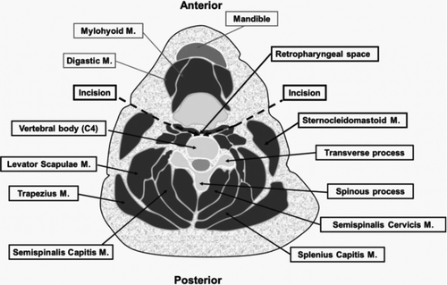
Fig. 2 Cervical instrumentation: (a) custom instrumentation mount screwed on C4 and (b) instrumentation configuration with 3D CT reconstruction.
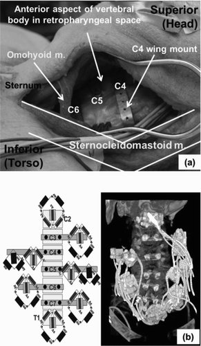
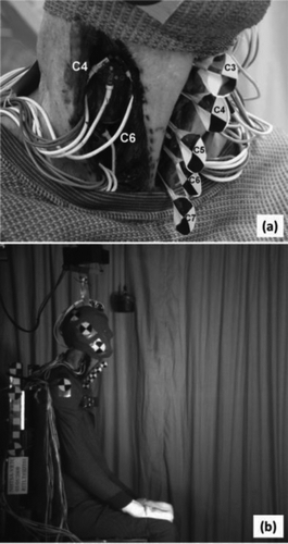
Fig. 3 Rear impact lab trial test: (a) C4 and C6 instrumentation and Steinmann pins with fiducials and (b) lateral view of test setup.
Validation Tests
In order to validate the proposed instrumentation technique, two 10 km/h impact trials were conducted using PMHS seated in a rigid rolling chair. An 82-year-old male subject (subject 1: weight, 72.1 kg; height, 175.0 cm) and a 91-year-old male subject (subject 2: weight, 63.5 kg; height, 179.0 cm) were used in these validation tests. The anthropometry measurements for the subjects are provided in Table A1 (see online supplement). The neck was dissected and each of the cervical vertebrae from C3 to C7 was instrumented as described in the Cervical Instrumentation section. The anterior portion of the neck was also dissected so that pins with attached fiducials (i.e., photo targets for video analysis) could be drilled into the anterior aspect of each of the vertebral bodies (C3–C7) to record kinematics using a high-speed camera (). This required that a portion of the anterior neck including the trachea, esophagus, and hyoid bone be split in half along a superior-to-inferior midline incision. Because it was not possible to install the Steinmann pins on the C2 or T1 vertebra due to interference with the chin and sternum, respectively, instrumentation blocks were also not installed on C2 or T1 for this validation test. It should be noted that although the realistic response of the neck may have been compromised by the additional anterior dissection and that complete
kinematics were not obtained because of the C2 and T1 omissions, the purpose of this study was to validate the instrumentation for a given vertebral level by comparing the kinematics from the high-speed video with the kinematics obtained from the instrumentation. Therefore, 5 separate vertebral levels (C3–C7) were deemed sufficient for this purpose. Once validated, however, the additional anterior dissection is not necessary in subsequent tests, thus avoiding any disruption of the anterior neck musculature.
The rigid rolling chair was positioned against a pneumatic ram system so that the chair would move forward when the ram system was fired, resulting in extension of the subject's neck. The subject's head was supported by a harness that was attached to an electromagnetic system such that the head would be released just prior to the event (). After positioning the subject, 3 points on each instrumentation block were digitized by a Faro arm device (Faro Arm Technologies, Lake Mary, FL) in order to define the initial orientation of the instrumentation blocks. The fiducials on the Steinmann pins were also digitized so that the data from the instrumentation could be transformed to the fiducials. High-speed video (1000 f/s) was recorded so that the kinematic data from the Steinmann pin fiducials could be compared to the kinematic data from the instrumentation. To provide a quantitative measure of this comparison, the normalized root mean squared deviation (NRMSD) was used as shown in EquationEq. (1). The NRMSD effectively provides an average percentage error over time between the kinematic data obtained from the video and instrumentation (Kang et al. Citation2011):
Fig. 4 General setup for the sled tests: (a) PMHS and (b) BioRID II.
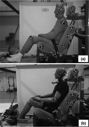
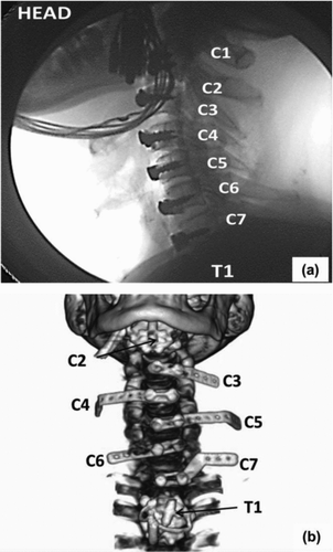
Fig. 5 PMHS cervical instrumentation (PMHS08) for the sled tests: (a) fluoroscopic image and (b) 3D CT reconstruction.
Rear Impact Sled Tests Using PMHS and BioRID II
Eight unembalmed PMHS (72 ± 14 years old, 78.4 ± 7.2 kg, and 175.8 ± 6.2 cm) were instrumented using the proposed cervical instrumentation technique. Rear impact PMHS sled tests were conducted at 2 moderate speeds (8.5 g and 17 km/h; 10.5 g and 24 km/h). A total of 14 rear impact sled tests were conducted with 7 PMHS exposed to the 17 km/h test and 7 exposed to the 24 km/h test. An experimental seat that was capable of simulating the dynamic seat back rotation of modern vehicle seat backs by considering the moment-rotation properties of a typical passenger vehicle seat was designed and used in the rear impact sled tests (Kang et al. Citation2012). The BioRID II was also tested under identical test conditions. Detailed information for the sled tests (i.e., sled pulse selection, experimental seat design, subject selection, subject instrumentation, and subject seating procedure) for both PMHS and BioRID II was reported in previous studies (Kang et al. [Citation2012] for PMHS; Moorhouse et al. [Citation2012] for BioRID II). Photographs of the general setup and initial positioning for the sled tests are shown in . For the PMHS cervical instrumentation, the 3aω blocks were installed on the anterior aspect of the cervical vertebral bodies (C2–C7), as described in the cervical instrumentation section. indicates the fluoroscopic image after installing the cervical instrumentation (C2–C7 and T1) and shows a 3D computed tomography (CT) reconstruction detailing how the wing mounts were screwed into each cervical vertebral body and wrapped around to the lateral aspect of the neck. The C2 and T1 instrumentation were installed directly on the anterior aspect of the vertebral body as shown in .
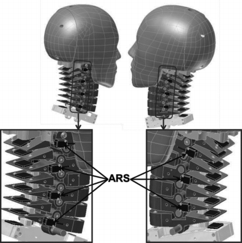
Threaded holes for installing angular rate sensors on the lateral aspect of the cervical vertebrae (C1–C7) of the BioRID II were created by the manufacturer (Humanetics, Inc. Plymouth, MI) so that the BioRID II had the capability of measuring neck angular kinematics, as shown in . The angular rate sensors were attached to each cervical vertebra in alternating fashion (C1, C3, C5, and C7 on the right side and C2, C4, and C6 on the left side). Linear kinematics for the BioRID II cervical spine were not recorded using accelerometers due to limitation of the space between each cervical vertebra of the BioRID II and because the pinned vertebral joints do not allow for relative translation. For this reason, even though the instrumentation on the PMHS cervical spine is capable of measuring rotations of each of the cervical vertebrae as well as axial and shear displacements, only rotations are reported in this study so that direct comparisons to the BioRID II cervical vertebrae rotations could be made. Axial and shear displacements will be reported in a separate study on the comparison of vertebral kinematics to resulting cervical spine injuries to investigate appropriate rear impact injury criteria.
Fig. 6 BioRID II cervical instrumentation (angular rate sensors shown in blue).
PMHS biomechanical targets for the cervical vertebrae rotations were created by first removing phase differences among the PMHS individual responses as described in Kang et al. (Citation2012). In order to quantify the biofidelity of the cervical spine of the BioRID II, biofidelity scores were computed using the updated NHTSA biofidelity ranking system (Rhule et al. Citation2013). Briefly, the phase difference between the dummy response and PMHS mean curve was removed to determine the shape and magnitude biofidelity (SM), and then the phase biofidelity (P) was evaluated by considering the difference in phase between the dummy response and PMHS mean curve relative to the standard acceptable phase difference as from the PMHS data. The values for SM and P are then combined using a vector magnitude methodology to provide a sense of the total biofidelity quality. Details on this updated biofidelity ranking system are provided in Rhule et al. (Citation2013). A biofidelity score of less than 1.0 indicates that the dummy response was less than one standard deviation different from the mean PMHS response, a biofidelity score less than 2.0 indicates that the dummy response was within 2 standard deviations of the mean PMHS response, and so forth. As a general rule, a biofidelity score of less than or equal to 2.0 is considered to represent good biofidelity for a dummy.
Data Transformation for Proposed Instrumentation
For the validation tests, data measured from the proposed instrumentation were transformed to the Steinmann pin fiducials (i.e., global frame) at each point in time, and coordinate systems were chosen according to SAE J211 (Society of Automotive Engineers Citation2007). The influence of gravity on the accelerometers was compensated for (Wu et al. Citation2009), because this has been shown to provide more accurate displacement data when computed from double numerical integration. The displacement data as determined from double integration of the accelerometer data did not begin to diverge until approximately 200 ms. The rotation data, however, were determined from single numerical integration of the data measured from the angular rate sensor so that the rotation data were less affected by numerical error and were valid beyond 200 ms. For the PMHS rear impact sled tests, data measured from the neck instrumentation were transformed to the origin of each vertebra and the linear displacement data of the cervical vertebrae in the global frame were obtained from double numerical integration (i.e., trapezoidal numerical integration) of the transformed accelerometer data, and the rotation data transformed to the global frame were determined from single numerical integration. The detailed transformation method for 3aω used in this study was provided in Kang et al. (Citation2011).
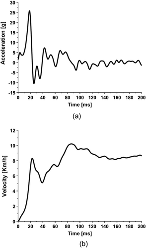
Fig. 7 Input pulse for the validation tests: (a) acceleration and (b) velocity.
Results
Validation Tests
The input acceleration pulse and velocity for a lab validation test are presented in . The transformed data (translational motion in the x- and z-directions, rotational motion in the y-direction) were compared to the corresponding data from the high-speed video analysis and shown in Figures A1–A3 (see online supplement). Qualitative evaluation of these curves for both subjects 1 and 2 revealed good agreement between the cervical kinematics obtained from video with the kinematics obtained from the instrumentation. To quantify this agreement, the NRMSD was calculated over the first 200 ms at each vertebral level, and the results are shown in
Table 1 Quantitative comparison between kinematics obtained from instrumentation and video using NRMSD
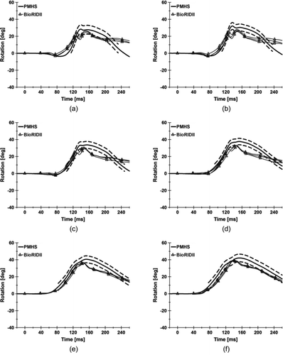
Fig. 8 Rotation of the cervical vertebrae relative to the sled in the global y-axis (17 km/h test): (a) C2, (b) C3, (c) C4, (d) C5, (e) C6, and (f) C7.
. For subject 1, the NRMSD was under 5 percent for every kinematic measure (x- and z-displacement and y-rotation) at C3 through C6 and for both displacement measures at C7, indicating that there was less than 5 percent error between the 2 methods. The NRMSD value for the C7 y-rotation was 14.4 percent, which indicated much higher disagreement between the 2 curves. Quantitative results for subject 2 also showed that the instrumentation matched the video analysis well with NRMSD values below 5 percent, with the exception of the y-rotations at the C3 (NRMSD = 7.6%) and C6 (NRMSD = 10.8%) vertebral levels. Overall, the NRMSD values were below 5 percent in 27 of the 30 comparisons and, based on these results, the proposed instrumentation appears to be capable of accurately measuring detailed cervical kinematics in rear impacts.
Rear Impact Sled Tests Using PMHS and BioRID II
Comparison of Cervical Vertebrae Rotations (Global Rotation Relative to Sled)
In order to visualize the PMHS cervical spine motions and assess them qualitatively, subject-specific cervical spine models for each PMHS were created using CT image data and are shown in Figure B1 (see online supplement). Sequential images of the cervical spine kinematics and the overall kinematics for an exemplar PMHS are shown for both 17 and 24 km/h tests in Figures B2 and B3 (see online supplement).
For all comparison plots between the BioRID II and PMHS biomechanical targets in this study, the BioRID II is denoted with triangle symbols and the PMHS biomechanical targets are denoted without symbols (solid line mean curve and dotted line standard deviation boundaries). shows the rotation of the cervical vertebrae for both the PMHS and BioRID II in the 17 km/h test. Qualitatively, the BioRID II exhibited comparable results to the PMHS in the 17 km/h test, and the SM scores for all cervical vertebrae of the BioRID II were less than 1.3 with an average value of 1.02 ± 0.22. Phase differences between the PMHS mean curve and the responses of the BioRID II appeared minimal qualitatively, and this was reflected quantitatively with an average P score of 0.08 ± 0.08 ().
Table 2 Biofidelity scores for the 17 km/h test
Fig. 9 Rotation of the cervical vertebrae relative to the sled in the global y-axis (24 km/h test): (a) C2, (b) C3, (c) C4, (d) C5, (e) C6, and (f) C7.
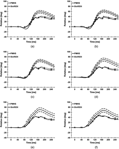
For the 24 km/h test, the cervical vertebrae of the BioRID II exhibited less rearward rotation than the PMHS at all vertebral levels, as depicted in . Qualitatively, none of the cervical vertebral levels showed good biofidelity in the 24 km/h test, and the SM scores for all vertebral levels ranged from 1.45 (C7) to 3.03 (C4) as shown in . The average SM score for all cervical vertebral levels was 2.27 ± 0.66, much greater than that in the 17 km/h test (1.02 ± 0.22). Phase differences between the PMHS mean curve and the responses of the BioRID II in the 24 km/h test were again minimal qualita-
tively, which was also reflected quantitatively (P score of 0.06 ± 0.03).
Table 3 Biofidelity scores for the 24 km/h test
Comparison of Relative Intervertebral Rotations of the Cervical Vertebrae
The relative intervertebral rotations of the cervical vertebrae (e.g., C2 rotation relative to C3 rotation denoted as C2/C3) were calculated for both the PMHS and the BioRID II from C2/C3 down to C6/C7 as shown in . The majority of peak intervertebral rotations (85% of PMHS and 87% of BioRID II) were a result of relative forward rotation or flexion (i.e., upper vertebrae were rotated forward relative to the lower vertebrae); thus, only negative peaks of relative intervertebral rotation (i.e., flexion) are seen in . For the 17 km/h test, average intervertebral rotations of the BioRID II at C3/C4 (P > .6), C5/C6 (P > .6), and C6/C7 (P > .4) were close to those measured in the PMHS, with the differences being less than 1° (). However, the BioRID II demonstrated less intervertebral rotation at the C2/C3 level (−1.8° BioRID II; −6.3° PMHS with P < .03) and the C4/C5 level (−4.4° BioRID II; −8.6° PMHS with P < .09). For the 24 km/h test, the average intervertebral rotations of the PMHS were greater than those of the BioRID II at all intervertebral levels but especially at the C2/C3 level (−6.6° PMHS; −1.2° BioRID II with P < .02) and the C4/C5 level (−11.7° PMHS; −3.7° BioRID II with P < .03).
Table 4 Peak relative intervertebral rotations (°)
Table 5 Comparison of global vertebral rotations measured in the current study compared to studies in the literature. Rotations in the current study are reported as mean (SD)
Discussion
Validation Tests
For subject 1, the C7 y-rotation had a large NRMSD value, whereas the rest of the NRMSD values were less than 5 percent. Inspection of the video revealed that the C7 fiducial was partially hidden behind the C6 fiducial, which likely affected the video analysis results for the rotation. In fact, the maximum peak rotations for C7 from the instrumentation and the video analysis were 28.2 and 23.5°, respectively. However, the average peak rotations of the cervical vertebrae from C3 through C6 as determined by the instrumentation and video were 32.0 ± 2.0° and 32.1 ± 1.2°, respectively. This indicates that the 28.2° of rotation obtained from the instrumentation may be more realistic than the 23.5° of rotation obtained from the video analysis, thus providing further evidence that there was an issue tracking the C7 fiducial.
Quantitative results for subject 2 showed that the NRMSD values were less than 5 percent, with the exception of the y-rotations at the C3 (NRMSD = 7.6%) and C6 (NRMSD = 10.8%) vertebral levels. It was found in the high-speed video that the Steinmann pin attached to C3 began to contact the head shroud at 30 ms, and then the fiducial on the Steinmann pin contacted the chin of the subject between 37 and 60 ms. This contact explains the discrepancy between the C3 rotations obtained from the instrumentation and the video analysis because the motion due to Steinmann pin contact would affect only the kinematics obtained from video analysis. A tracking issue similar to that observed in the C7 fiducial of subject 1 was found for the C6 fiducial of subject 2. The C6 fiducial for subject 2 was partially hidden behind the C5 fiducial, resulting in 8.4° of maximum forward rotation at 23 ms, which is unrealistic compared to the other cervical vertebrae (maximum forward rotation of 2.3–3.0°).
Rear Impact Sled Tests Using PMHS and BioRID II
Many studies have looked at the gross kinematics of the head and T1 of the BioRID II (Davidsson, Flogard, et al. Citation1999; Kim et al. Citation2003; Mallory and Stammen Citation2007; Philippens et al. Citation2002), but no previous studies actually measured individual cervical kinematics of the BioRID II by installing sensors on each cervical vertebra. The cervical spine of the BioRID II exhibited good biofidelity in the 17 km/h test, with a biofidelity score of 1.03 ± 0.21. However, the responses in the 24 km/h did not show good agreement with the PMHS responses, having worse biofidelity scores (2.27 ± 0.66). These results reflect the fact that the BioRID II cervical spine was designed to model low-speed rear impacts on the order of 10 km/h (Davidsson, Flogard, et al. Citation1999). However, it is important to evaluate the biofidelity of the BioRID II not only in low-speed impact scenarios but also at moderate to high speeds so that seat design using the BioRID II is optimized to provide protection to occupants at all speeds.
It should be noted that the responses of the cervical spine of the BioRID II were dependent on the responses of each region of the spine (i.e., cervical, thoracic, lumbar, sacral, and coccygeal) because they are all connected. For example, poor biofidelity in the cervical spine could be due simply to propagation of poor lower spine biofidelity, although this was not investigated in this study. In Moorhouse et al. (Citation2012), the 24 km/h T1 biofidelity of the BioRID II was found to be poor (using data from the same tests reported herein) due to large spikes in the x- and z-accelerations upon T1 contact with the head restraint. It was difficult to distinguish in this study whether the limited rotation responses of the BioRID II cervical spine in the 24 km/h test were due to poor biofidelity of the cervical spine or were an artifact due to the T1 interaction with the head restraint causing the large acceleration spikes.
Occupant ramping motion up the seat back also affects the cervical kinematics. In these tests, the PMHS head stayed close to the initial position (relative to the sled) due to inertia, whereas the thorax rotated rearward and the body ramped up along the seat back (Kang et al. Citation2012). Consequently, C2 and C3 initially rotated forward (, , and ) in both the 17 and 24 km/h test due to the combination of ramping-up motion and inertia of the head. The PMHS exhibited much larger ramping motion up the seat back than the BioRID II in the 24 km/h test, whereas the ramping motion up the seat back between the PMHS and BioRID II was much more similar in the 17 km/h test (Kang et al. Citation2012; Moorhouse et al. Citation2012). These differences in whole-body kinematics may influence the cervical spine rotations and contribute to the finding that the BioRID II cervical spine exhibited comparable performance to the PMHS in the 17 km/h test but not in the 24 km/h test.
Comparison of Cervical Vertebrae Rotations (Global Rotation Relative to Sled)
shows global rotations of the cervical vertebrae C2 through C7 measured in the current study compared to studies in the literature using a high-speed X-ray system. Deng 01 and Deng 02 are cervical vertebrae rotations from 2 subjects tested with a head restraint in Deng et al. (Citation2000), and White 01 and White 02 are cervical vertebrae rotations from 2 subjects tested with a head restraint in White et al. (Citation2009). Cervical vertebrae rotations from the Deng et al. (Citation2000) study were slightly greater than those obtained from the 17 km/h tests in the current study. Upper cervical (C2 and C3) rotations measured from the White et al. (Citation2009) study were smaller than those found in the current study, whereas lower cervical rotations (C5 and C6) were comparable to those from the 17 km/h tests in the current study, especially White 01.
Table 6 Comparison of relative intervertebral rotations measured in the current study compared to studies in the literature. Rotations are reported as mean (SD)
Comparison of Relative Intervertebral Rotations of the Cervical Vertebrae
Relative intervertebral rotations in rear impacts have been reported using isolated cervical spine specimens (Ivancic et al. Citation2006; Panjabi et al. Citation2005), where the isolated cervical spine specimens with a custom surrogate head (weight of 3.3 kg) were exposed to 3.5, 5, 6.5, and 8 g rear impacts, and the intervertebral kinematics were measured by high-speed cameras. Deng et al. (Citation2000) also reported relative intervertebral rotations measured by a high-speed X-ray system in low-speed rear impact conditions (5–9.8 g and 5–16 km/h) using full-body PMHS. The intervertebral rotations resulting from these studies in the literature are compared to the current study in , with the relative extension values highlighted in light gray and the relative flexion values shown in dark gray.
The maximum peak values for the intervertebral rotations (C2/C3 through C6/C7) in the Panjabi et al. (Citation2005) study and Ivancic et al. (Citation2006) study exhibited only positive values (i.e., relative extension), wheras those from the current study were negative (i.e., relative flexion), which can be explained by the very different test environments. Both the Panjabi et al. (Citation2005) study and Ivancic et al. (Citation2006) study used isolated cervical spines with the upper thoracic area (T1 level) fixed to a mini-sled system, so typical thoracic seat back interaction expected in a rear impact could not be taken into account. This fixation of T1 constrains its movement to be horizontal in the moving direction of the mini-sled, thus facilitating relative extension for the intervertebral rotations.
The Deng et al. (Citation2000) study, however, used full-body PMHS in low-speed rear impacts with and without a head restraint, so no such constraint was imposed on the upper spine. shows that for Deng et al.'s (Citation2000) tests with a head restraint, the intervertebral rotations for the upper cervical spine (C2–C4) were very similar to those found in this study, whereas the intervertebral rotations for the lower cervical spine (C4–C7) exhibited opposite polarity (i.e., extension vs. flexion). This was likely due to the difference in seat systems between the 2 studies. A rigid seat was used in the Deng et al. (Citation2000) study, whereas the experimental seat utilized in this study had a rotating seat back (Kang et al. Citation2012). With a rotating seat back, the upper thoracic spine rotates rearward relative to the sled because it is coupled to the seat back and then the adjacent cervical vertebrae sequentially rotate rearward while the head stays close to the initial angle (0°) due to head lag. This causes initial relative flexion of all of the cervical vertebrae. However, in the rigid seat condition the upper thoracic spine rotates rearward less than in a rotating seat back. Consequently, the adjacent lower cervical spine rotates rearward more than the upper thoracic spine, resulting in intervertebral extension for the lower cervical spine, whereas the upper cervical spine still exhibits intervertebral flexion because it is dominated by the head lag effect.
For the seat back rotational kinematics in this study shown in Figures B2 and B3 and documented in Kang et al. (Citation2012), the intervertebral rotation was dominated by flexion () even though the cervical vertebrae rotated rearward with respect to the global coordinate system (i.e., sled). A similar influence of seat back rotation on head–neck kinematics was documented in Geigl et al. (Citation1994), where it was reported that the plastic deformation/rotation of the seat back of a production seat caused large flexion of the relative kinematics of the head to C4 and C4 to C7. The differences observed in cervical spine kinematics between the different test and/or seat configurations described in this section indicate that seat back deformation and/or rotation is a variable that needs to be considered when designing seats to reduce the risk of cervical spine injury.
The influence of the seat back rotation in this study was evident in the intervertebral kinematics of the BioRID II, where primarily intervertebral flexion was also observed. Initial design targets of the ROM between 2 adjacent vertebrae in the cervical spine of the BioRID II were 11.5° for extension and 4.5° for flexion (Davidsson et al. Citation1998). However, results from the PMHS in this study showed average intervertebral flexion rotations ranging from 5.3 to 11.7° (), much greater than the design target (4.5°) of the BioRID II. also shows that the BioRID II reached maximum intervertebral flexion rotation capacity of 4.5° in both the 17 km/h (C3/C4 through C6/C7) and 24 km/h (C5/C6 and C6/C7) tests. Based on the results from this study, the intervertebral ROM of the cervical spine for the BioRID II may need to be expanded in flexion and possibly specified separately for each intervertebral level because it appears that the ROM at the C4/C5 level (i.e., middle cervical spine) should be larger than the other levels (). In addition to the flexion ROM, the flexion stiffness of the BioRID II cervical spine may also need to be improved based on the biofidelity observed in the 24 km/h test. However, the influence of different seating systems on cervical spine kinematics and the potential need for improved flexion ROM and/or flexion stiffness of the BioRID II cervical spine needs to be further assessed in future testing using actual production seats.
Limitations
First, this study was somewhat limited by a small sample size of PMHS. Two PMHS were used in the initial validation tests and then 8 PMHS were used in the sled tests to generate the biomechanical response targets (a total of 7 PMHS biomechanical responses obtained at 2 different speeds). However, because rear impact biomechanical responses from PMHS are limited in the literature, a total of 14 PMHS sled tests using 8 PMHS should help to better understand responses in rear impacts.
Unlike low-speed rear impact studies using volunteers, this study focused on moderate-speed rear impacts in the severity realm where injuries might occur, so PMHS had to be used. Therefore, when applying these data to the real world, or comparing to dummy responses that are intended to represent a live unaware occupant, there is an inherent assumption that the difference in muscle activation between PMHS and live unaware occupants does not significantly alter the resulting head–neck kinematics, especially during the phase of impact most likely to result in injury. The validity of this assumption with respect to (1) passive resistance and tethering of the spine; (2) pre-impact muscle activation associated with bracing; (3) post-impact muscle activation due to reflexes; and (4) pre-impact muscle activation required to stabilize the neck and keep the head in an upright position is supported extensively in Kang et al. (Citation2012).
In this study, 3 accelerometers and 3 angular rate sensors were attached to each cervical vertebra. The mass of the instrumentation including a block, 3 accelerometers, 3 angular rate sensors, screws, and cables was 0.032 kg. Bertholon et al. (Citation2000) measured 2D cervical kinematics by installing mounting blocks containing 2 accelerometers and one angular rate sensor on the anterior aspect of the second and fifth cervical vertebrae (C2 and C5) as well as T1. They reported that their instrumentation weighed 0.050 kg, which was about 25 percent of the mass of one vertebral level (vertebra with soft tissues). Based on this assessment, the mass of the proposed instrumentation herein was approximately 15 percent of the mass of one vertebral level. Considering that the effective mass of each vertebral level during the rear impact events would be larger than the actual mass due to the resistance from passive ligaments and muscles, the mass of the instrumentation would actually constitute less than 15 percent of the effective mass of each vertebral level. However, future work will be carried out to quantify any effect that the instrumentation may have on neck kinematics, by directly comparing the cervical kinematics for a given neck with and without instrumentation (e.g., modeling approach or carefully controlled high-speed imaging).
For the rear impact sled tests, an experimental seat designed specifically for the biofidelity evaluation of rear impact ATDs was used (Kang et al. Citation2012). Therefore, the seat was designed to be durable and repeatable, and load cells were installed within the seat to assess external biofidelity of the dummies. These demands caused the framework of the seat and head restraint to be heavier and less compliant than a production seat, even though it included seat cushions and padding. In addition, in order to have the seat be more realistic than a fixed seat back configuration, a spring–damper system was used to achieve a specific amount of total seat back rotation during the rear impact based on average rotational stiffness values determined from a wide range of seats (Molino Citation1998). Despite these efforts, the seat back responses and resulting occupant kinematics in the experimental seat may have differed from production seats mostly due to the less compliant seat frame of the experimental seat in conjunction with a more uniform seat back rotation due to the constant stiffness spring damper system. In a production seat there is less initial seat back rotation as the occupant tends to first translate and sink more into the compliant seat cushion/framework until it bottoms out, at which time the majority of seat back rotation begins. Therefore, a production seat could be expected to generally yield less relative intervertebral flexion than the experimental seat. In future studies, a similar comparison between PMHS and BioRID II intervertebral kinematics will be carried out in production seats.
Conclusions
A new instrumentation and dissection technique was proposed in which instrumentation (3 accelerometers, 3 angular rate sensors) capable of measuring the detailed intervertebral kinematics of the cervical spine were installed on the anterior aspects of each vertebral body with minimal muscular damage. The instrumentation was validated by conducting 10 km/h rear impact tests with 2 PMHS in a rigid rolling chair, and NRMSD values were below 5 percent in 27 of the 30 comparisons. After this validation, a total of 14 sled tests using 8 male PMHS were conducted in 2 moderate-speed rear impacts (8.5 g, 17 km/h; 10.5 g, 24 km/h). The BioRID II was also tested under identical conditions with an angular rate sensor installed on each of the cervical vertebrae so that rotations of the cervical spine of the BioRID II could be compared to those measured from the PMHS. The results showed that the BioRID II exhibited comparable results to the PMHS in the 17 km/h test. For the 24 km/h test, the cervical vertebrae of the BioRID II exhibited less rearward rotation than the PMHS at all levels (C2–C7). The average biofidelity score for C2 through C7 was 1.02 for the 17 km/h test and 2.27 for the 24 km/h test. These results reflect the fact that the fully articulated spine of the BioRID II was designed and tuned to model low-speed rear impacts. The intervertebral rotations for both the PMHS and the BioRID II were primarily relative flexion rotations even though the cervical vertebrae rotated rearward with respect to the global coordinate system.
Supplementary Materials
Download Zip (2.1 MB)Acknowledgments
This article not subject to US copyright law.
References
- Bertholon , N , Robin , S , Le Coz , J Y , Potier , P , Lassau , J P and Skalli , W . Human head and cervical spine behaviour during low-speed rear-end impacts: PMHS sled tests with a rigid seat . Paper presented at: International Research Council on Biomechanics of Injury (IRCOBI) Conference; Montpellier, France, September 20–22 ,
- Bortenschlager , K , Kramberger , D Barnsteiner , K . 2003 . Comparison tests of BioRID II and RID2 with regard to repeatability, reproducibility and sensitivity for assessment of car seat protection potential in rear-end impacts . Stapp Car Crash J. , 47 : 473 – 488 .
- Cappon , H J , Philippens , MMGM , van Ratingen , M R and Wismans , JSWM . Evaluation of dummy behaviour during low severity rear impact . Paper presented at: International Research Council on Biomechanics of Injury (IRCOBI) Conference; Montpellier, France, September 20–22 ,
- Cappon , H , Philippens , M , van Ratingen , M and Wismans , J . 2001 . Development and evaluation of a new rear-impact crash dummy: the RID 2 . Stapp Car Crash J. , 45 : 225 – 238 .
- Croft , A and Philippens , M . 2007 . The RID2 biofidelic rear impact dummy: a pilot study using human subjects in low speed rear impact full scale crash tests . Accid Anal Prev. , 39 : 340 – 346 .
- Davidsson , J , Flogard , A , Lovsund , P and Svensson , M Y . 1999 . BioRID P3—design and performance compared to Hybrid III and volunteers in rear impacts at ΔV = 7 km/h . Stapp Car Crash J. , 43 : 253 – 265 .
- Davidsson , J , Lovsund , P , Ono , K , Svensson , M Y and Inami , S . A comparison between volunteer, BioRID P3 and Hybrid III performance in rear impacts . Paper presented at: International Research Council on Biomechanics of Injury (IRCOBI) Conference; Sitges, Spain, September , pp. 23 – 24 .
- Davidsson , J , Svensson , M Y Flogard , A . BioRID I—a new biofidelic rear impact dummy . Paper presented at: International Research Council on Biomechanics of Injury (IRCOBI) Conference; Göteberg, Sweden, September , pp. 16 – 18 .
- Deng , B , Begeman , P C , Yang , K H , Tashman , S and King , A I . 2000 . Kinematics of human cadaver cervical spine during low speed rear-end impacts . Stapp Car Crash J. , 44 : 171 – 188 .
- Geigl , B C , Steffan , H , Leinzinger , P , Roll Mühlbauer , M and Bauer , G . The movement of head and cervical spine during rearend impact . Paper presented at: International Research Council on Biomechanics of Injury (IRCOBI) Conference; Lyon, France, September , pp. 21 – 23 .
- Gotou , T , Ono , K , Ito , M and Matuoka , F . A comparison between BioRID AND Hybrid III head/neck/torso response in middle speed sled rear impact tests . Paper presented at: 17th International Technical Conference on the Enhanced Safety of Vehicles; Stuttgart, Germany, June , pp. 15 – 18 .
- Hu , A S , Bean , S P and Zimmerman , R M . 1977 . Response of belted dummy and cadaver to rear impact . Stapp Car Crash J , 21 : 589 – 625 .
- Ishikawa , T , Okano , N , Ishikura , K and Ono , K . An evaluation of prototype seats using BioRID-P3 and Hybrid III with TRID neck . Paper presented at: International Research Council on Biomechanics of Injury (IRCOBI) Conference; Montpellier, France, September , pp. 20 – 22 .
- Ivancic , P C , Panjabi , M M , Tominaga , Y and Malcolmson , G F . 2006 . Predicting multiplanar cervical spine injury due to head-turned rear impacts using IV-NIC . Traffic Inj Prev. , 7 : 264 – 275 .
- Ivancic , P C , Sha , D and Panjabi , M M . 2009 . Whiplash injury prevention with active head restraint . Clin Biomech. , 24 : 699 – 707 .
- Kallieris , D , Rizzetti , A , Mattern , R , Thunnissen , J and Philippens , M . Cervical human spine loads during traumatomechanical investigations . Paper presented at: International Research Council on Biomechanics of Injury (IRCOBI) Conference; Dublin, Ireland, September , pp. 11 – 13 .
- Kang , Y , Moorhouse , K and Bolte , J . 2011 . Measurement of 6 DOF head kinematics in impact conditions employing six accelerometers and three angular rate sensors (6aw configuration) . J Biomech Eng. , 133 : 111007-1 – 111007-11 .
- Kang , Y , Moorhouse , K , Donnelly , B , Herriott , R , Mallory , A and Bolte , J H . 2012 . Biomechanical responses of PMHS in moderate-speed impacts and development of response targets for evaluating the internal and external biofidelity of ATDs . Stapp Car Crash J. , 56 : 105 – 170 .
- Kim , A , Anderson , K F Berliner , J . 2003 . A biofidelity evaluation of the BioRID II, Hybrid III and RID2 for use in rear impacts . Stapp Car Crash J. , 47 : 489 – 523 .
- Mallory , A and Stammen , J . 2007 . Comparative Evaluation of Rear Impact ATDs Static Seat Interaction and Dynamic Testing , Washington, DC : National Highway Traffic Safety Administration . NHTSA Docket No. 2007-27986-19
- Mertz , H J and Patrick , L M . 1967 . Investigation of the kinematics and kinetics of whiplash . Stapp Car Crash J. , 11 : 267 – 317 .
- Molino , L . 1998 . Determination of Moment-Deflection Characteristics of Automobile Seat Backs , Washington, DC : National Highway Traffic Safety Administration . NHTSA Docket No. 1998-4064-26
- Moorhouse , K , Kang , Y , Donnelly , B , Herriott , R and Bolte , J H . 2012 . Evaluation of the internal and external biofidelity of current rear impact ATDs to response targets developed from moderate-speed rear impacts of PMHS . Stapp Car Crash J. , 56 : 171 – 229 .
- National Highway Traffic Safety Administration . 2004 . Federal Motor Vehicle Safety Standards; Head Restraints (FMVSS 202a) , Washington, DC : National Highway Traffic Safety Administration . 49 CFR Part 571, Docket No. NHTSA-2004-19807
- Ono , K , Kaneoka , K , Wittek , A and Kajzer , J . 1997 . Cervical injury mechanism based on the analysis of human cervical vertebral motion and head–neck–torso kinematics during low-speed rear impacts . Stapp Car Crash J. , 41 : 339 – 356 .
- Panjabi , M M , Cholewicki , J , Nibu , K , Babat , L B and Dvorak , J . 1998 . Simulation of whiplash trauma using whole cervical spine specimens . Spine (Phila Pa 1976). , 23 : 17 – 24 .
- Panjabi , M M , Ito , S , Ivancic , P C and Rubin , W . 2005 . Evaluation of the intervertebral neck injury criterion using simulated rear impacts . J Biomech. , 38 : 1694 – 1701 .
- Philippens , M , Cappon , H van Ratingen , M . 2002 . Comparison of the rear impact biofidelity of BioRID II and RID2 . Stapp Car Crash J. , 46 : 461 – 476 .
- Philippens , M , Wismans , J , Cappon , H , Yoganandan , N and Pintar , F . Whole body kinematics using post mortem human subjects in experimental rear impact . Paper presented at: International Research Council on Biomechanics of Injury (IRCOBI) Conference; Montpellier, France, September 20–22 ,
- Rhule , H , Moorhouse , K , Donnelly , B and Kang , Y . A methodology for generating objective targets for quantitatively assessing the biofidelity of crash test dummies . Paper presented at: 23rd International Technical Conference on the Enhanced Safety of Vehicles (ESV) , Seoul, Korea, May 27–30
- Sano , K , Dokko , Y , Negishi , H , Goto , T , Ono , K and Warren , J . Development of a cervical spine injury reducing seat system using BioRID II dummy . Paper presented at: 17th International Technical Conference on the Enhanced Safety of Vehicles; Amsterdam, The Netherlands , June 4–7
- Siegmund , G P , Heinrichs , B E and Lawrence , J M . 2001 . Kinetic and kinematic responses of the RID 2a, Hybrid III and human volunteers in low-speed rear-end collisions . Stapp Car Crash J. , 45 : 239 – 256 .
- Siegmund , G P , King , D J , Lawrence , J M , Wheeler , J B , Brault , J R and Smith , T A . 1997 . Head/neck kinematic response of human subjects in low-speed, rear-end collisions . Stapp Car Crash J. , 41 : 357 – 385 .
- Society of Automotive Engineers . 2007 . Instrumentation for Impact Test, Part 1: Electronic Instrumentation , Warrendale, PA: Society of Automotive Engineers . SAE J211/1
- Stemper , B D , Yoganandan , N and Pintar , F A . 2003 . Gender dependent cervical spine segmental kinematics during whiplash . J. Biomech. , 36 : 1281 – 1289 .
- Sundararajan , S , Prasad , P Demetropoulos , C K . 2004 . Effect of head–neck position on cervical facet stretch of post mortem human subjects during low speed rear end impacts . Stapp Car Crash J. , 48 : 331 – 372 .
- Tencer , A F , Mirze , S and Huber , P . 2004 . A comparison of injury criteria used in evaluating seats for whiplash protection . Traffic Inj Prev. , 5 : 56 – 66 .
- Van Den Kroonenberg , A , Philippens , M , Cappon , H , Wismans , J , Hell , W and Langwieder , K . 1998 . Human head–neck response during low-speed rear end impacts . Stapp Car Crash J. , 42 : 207 – 222 .
- White , N A , Begeman , P C Hardy , W N . 2009 . Investigation of Upper Body and Cervical Spine Kinematics of Post Mortem Human Subjects (PMHS) During Low-Speed, Rear-End Impacts , Warrendale , PA : Society of Automotive Engineers . SAE Paper No. 2009-01-0387
- Wu , J , Shi , Y , Kang , J and Nusholtz , G S . 2009 . Using Trial-Axial Angular Rate Sensor and Accelerometer to Determine Spatial Orientation and Position in Impact Tests , Warrendale , PA : Society of Automotive Engineers . SAE Paper No. 2009-01-0055
- Yoganandan , N , Pintar , F , Stemper , B , Schlick , M , Philippens , M and Wismans , J . 2000 . Biomechanics of human occupants in simulated rear crashes: documentation of neck injuries and comparison of injury criteria . Stapp Car Crash J. , 44 : 189 – 204 .
- Zellmer , H , Stamm , M , Seidenschwang , A and Brunner , A . Enhancement of seat performance in low-speed rear impact . Paper presented at: 17th International Technical Conference of the Enhanced Safety of Vehicles; Amsterdam, The Netherlands , June 4–7