
 ?Mathematical formulae have been encoded as MathML and are displayed in this HTML version using MathJax in order to improve their display. Uncheck the box to turn MathJax off. This feature requires Javascript. Click on a formula to zoom.
Abstract
Although conventional gait pattern control in humanoid robots is typically performed on flat terrains, the roads that people walk on every day have bumps and potholes. Therefore, to make humanoid robots more similar to humans, the movement parameters of these robots should be modified to allow them to adapt to uneven terrains. In this study, to solve this problem, reinforcement learning (RL) was used to allow humanoid robots to engage in self-training and automatically adjust their parameters for ultimate gait pattern control. However, RL has multiple types, and each type has its own benefits and shortcomings. Therefore, a series of experiments were performed, and the results indicated that proximal policy optimization (PPO), combining advantage actor-critic and trust region policy optimization, was the most suitable method. Hence, an improved version of PPO, called PPO2, was used, and the experimental results indicated that the combination of deep RL with data preprocessing methods, such as wavelet transform and fuzzification, facilitated the gait pattern control and balance of humanoid robots.
1. Introduction
With the rapid development of technology, several advancements have been observed in the field of robotics, with the most popular robotic application currently being mobile robots. Over the years, the development of robotics has progressed from robotic arms to robots with a variety of gait patterns, such as wheeled robots and quadruped robots. In this study, the type of robot discussed was a biped robot, whose gait pattern is highly similar to that of humans, and the model used was ROBOTIS OP3. Gait pattern, controlled by the body, was initially used by biologists to describe the movement pattern of an organism. However, this technique has been commonly applied to robots to record the movements of each robot leg and its gait pattern. This study focused on reinforcement learning (RL), a subset of machine learning whose aim is to explore how agents decide their actions depending on the environment (state) and what policies increase the reward. Given this concept, the present study also investigated how a humanoid robot can learn to walk on uneven terrain. Li et al.[Citation1] studied the tracking and control of aircraft. However, the tracking data were difficult to obtain because of occlusion. Therefore, an estimator and a controller were used to solve this problem. In the present study, a controller was used to control the robot’s gait pattern. The robot’s data were collected using a sensor, and the controller was used to change the robot’s gait pattern. Yu et al.[Citation2] used an RL boundary controller to address traffic congestion on highways. Proximal policy optimization (PPO), a neural network-based[Citation3] policy gradient algorithm, was applied to the controller. Although the training was conducted with an analog model, it had an academic value. Hence, in the present study, PPO2 was used, which was derived from PPO, and RL was embedded in the controller.
Conventional gait generators are typically used to plan the trajectory of the center of mass (CoM) through the zero-moment point (ZMP). Sato et al.[Citation4] used a predetermined gait pattern. Despite this method being commonly used, it could not handle certain situations. Because the gait pattern was preplanned, it had to be analyzed to ensure that the robot walked stably. In addition, the robot had to be trained to adjust the trajectory of its CoM and gait pattern when it encountered accidental collisions while walking. To parameterize the gait cycle phase and facilitate the application of this method to wearable robots, Villarreal et al.[Citation5] investigated the phase angle of hip joints. In the present study, more phase angles, such as the phase angles of legs and ankles, were included to control the humanoid robot. Li et al.[Citation6] proposed a method to control foot contact force. This contact force control was achieved by comparing the actual and desired force, through body stability, and by tracking the trajectory of the divergent component of motion (DCM). This method allowed the robots to walk more stably on uneven terrains. In the present study, the robot was capable of self-learning but still required some training.
Kyriakoulis and Gasteratos[Citation7] proposes a fuzzy hierarchical system to fuse visual and inertial pose estimations for an indoor volant robot. The system has three levels, where the first correct inertial measurement errors, the second fuses visual and corrected inertial measurements, and the third produces the final output. Results demonstrate the system’s accuracy and real-time feasibility. Wu and Li[Citation8] used a fuzzy controller to adjust a robot’s gait pattern when it encountered accidental collisions. Dong et al.[Citation9] used the feedback control of the DCM to compensate for the error of the linear inverted pendulum model (LIPM), an open-looped system. The DCM controller maintained the robot’s stability while it was walking. However, similar to the results of Wu and Li,[Citation8] Dong et al.,[Citation9] and Li et al.,[Citation10] the LIPM could not resolve unstable situations, such as complex terrains or external forces. Thus, Li et al.[Citation10] used a feedback system based on particle swarm optimization and a long short-term memory neural network. Chen and You[Citation11] used machine learning and data-driven robust model predictive control (DDRMPC) to perform automatic climate control in a greenhouse. The temperature, humidity, and concentration of carbon dioxide were regulated. By setting the parameters and greenhouse model and feeding back the greenhouse measurements to the machine learning and DDRMPC systems, a greenhouse that could automatically adapt to the climate was finally obtained. Zhang et al.[Citation12] focused on the tracking and control of time-delayed multiple-spacecraft systems. Fuzzification was applied to the controller, and this fuzzy-based controller was confirmed to be more efficient than a conventional, non-linear, compensation controller. Peng et al.[Citation13] studied autonomous surface vehicles. In the control loop, a fuzzy system was incorporated into the estimator to approximate the unknown dynamics according to the inputs and outputs. The simulation results indicated that the proposed method was effective. Accordingly, in the present study, fuzzy logic[Citation14] was adopted to increase the efficiency of data computation.
Hwang et al.[Citation15] used Q-learning to allow a biped robot to walk straight. The angles of the robot’s joints were adjusted, and posture training was conducted. If the latest posture was determined to be more satisfactory than the preceding one, then Q-learning was used to guide the robot with the current optimal posture and continue the training session to obtain a more suitable posture to walk forward. Piperakis et al.[Citation16] used the sensors inside a robot, such as the inertial measurement unit (IMU) and joint encoder, to acquire the robot’s body information and estimate its non-linear walking state. A rigid body estimator was then transformed into a CoM calculator. By combining and analyzing the two factors, the robot’s non-linear state during walking could be estimated according to the external effects. Lin et al.[Citation17] used Q-learning to balance a robot’s gait pattern. Force sensors were installed to confirm the slope of the ground and ZMP. After the ground on which the robot was standing and the ZMP were identified, the robot was trained using Q-learning to maintain its balance while walking on different slopes. On the basis of multiple posture simulations, Rakovic et al.[Citation18] obtained the projection of the center of mass (PCM) and ZMP in footprints. The most suitable posture for the next step could be arranged for the robot according to the PCM and ZMP obtained in each previous posture. Yu et al.[Citation19] indicated that vector calculation is a suitable method to allow robots to walk on a slope. The torques in the x, y, and z directions of the return of each joint revealed the location of the robot’s CoM and the inclination of the standing robot. According to said information and through vector calculation, the trajectory to proceed on slopes could be obtained. Khan and Chen[Citation20] attempted to acquire the natural oscillation of biped motion to approximate a robot’s gait pattern to the actual situation. The angle of the leg was obtained, and several parameters were set, including the mass and length of the leg and the elastic constant, to theoretically calculate the natural oscillation frequency. Comparison between the theoretical and simulated values determined whether the result was optimal. If so, the result was introduced into a new simulation to obtain a gait pattern closer to the actual situation. Zhao and Iwasaki[Citation21] used a central pattern generator to make movements more harmonious. Because an appropriate control framework and feedback system were used, more suitable natural and damping frequencies were obtained, and a more accurate movement trajectory was acquired on a computer when the robot was moving.
2. System architecture
RL is a method used to repeatedly learn something through interactions in a dynamic environment with the help of computers. RL allows robots to learn how to walk, hold objects, or perform a task. This trial-and-error method is similar to human behavior. Humans typically tend to determine the most optimal way and take action as soon as possible. If they encounter any difficulties, they tend to adjust their policy, learn from the experience, and avoid adopting the same unsatisfactory policy.
As a simple example, because children like candy, their parents promise them that they will buy them candy if they do well in their exams (positive reward). Conversely, they will be punished if they do poorly in their exams (negative reward). To obtain a positive reward, the children tend to study hard. After a few trials, they become aware of how to achieve high marks to obtain a positive reward.
In artificial intelligence, an agent can accomplish a goal during its learning process in an environment. RL consists of three elements: an actor, an environment, and a reward function. The environment and reward cannot be controlled and can only be preset. The actor, however, can be regulated to obtain positive rewards by adjusting the policy. In the present study, this method was adopted, the robot’s gait pattern was analyzed, and a code was written to define the reward system to allow the robot to perform the optimal gait pattern after multiple instances of training.
PPO is an RL algorithm used in several systems. The following is an introduction to the terms on-policy and off-policy. An on-policy is a situation in which the interaction of the agent with the environment is the same as the training of the agent, whereas an off-policy is a situation in which the interaction of the agent with the environment is different from the training of the agent. The on-policy constitutes learning during training, whereas the off-policy constitutes learning by observing the training of other agents. Because the policy gradient theorem is a type of an on-policy, the actor changes every time it is sampled. The original data also become no longer applicable. Therefore, the training becomes time-consuming and inefficient. shows a schematic of RL.
Figure 1. Reinforcement learning.[Citation22]
![Figure 1. Reinforcement learning.[Citation22]](/cms/asset/1cd174e2-3e20-4e5f-a366-fa054b4081cb/uopt_a_2222146_f0001_c.jpg)
In the algorithm, θ and θk are different (θ is a policy parameter). θk is a reference for θ, revealing the condition of interaction with the environment for training θ (off-policy) and increasing the training efficiency. In this scenario, the same data can be used for multiple instances of training, which is considered to be useful. However, although data recollection is not required, this method has some shortcomings. To transform an on-policy into an off-policy, importance sampling should be performed on the policy. The difference between θ and θk should also not be too large. If the difference is large, overfitting occurs. For example, if θk is much higher than θ, then θ does not learn from θk and only imitates it, which is referred to as overfitting. To avoid this problem, PPO should be used. PPO is a method used to add a constraint term to an algorithm.[Citation16] The constraint term here is ßKL(θ, θk), which limits the difference between θ and θk:
(1)
(1)
(2)
(2)
where KL(θ, θk) is the action Kullback–Leibler (KL) divergence (also known as relative entropy) of the outputs of the two models, which is used to measure the degree of similarity between the two models. As stated earlier, the two models should be as similar as possible. KL is the distance of the behavior and not the distance of the parameter. Therefore, the KL term is the average of the relative entropy of the values between different output states. The main procedure of PPO is to initialize the policy parameter θ0 first and then determine θk to collect data. After the data are collected, EquationEquation (1)
(1)
(1) is used to update θ. During this process, ß can also be updated. If the difference between θ and θ′ is large, then this means that ßKL(θ, θk) is too small to be substituted into the equation. Therefore, ß should be made larger. By contrast, if the difference between θ and θk is small, then ß should be made smaller. However, because calculating the relative entropy is not easy, PPO2 is required for derivation. The following is the equation of PPO2:[Citation23]
(3)
(3)
where the min function selects smaller data during the calculation process and the clip function limits the output value. When the output value is lower than 1 − ε, the value of 1 − ε is considered; when the output value is higher than 1 + ε, the value of 1 + ε is considered; when the output value is between 1 + ε and 1 − ε, the original value is considered.
Generally, the aforementioned equation can be used to change the training data to determine which method is more satisfactory. The first method is to use acceleration as the training data, and the second method is to calculate the standard deviation of acceleration and fuzzify the data to optimize the training process.
Fuzzy logic can be used in several fields. Simply put, fuzzy logic makes the standard fuzzy, that is, unclear. For example, if a person weighs 80 kg, this person is said to be heavy. However, if a person weighs 79.5 kg, then this person would not be called slim because the difference between the two weights is small. Fuzzification is used in machine learning to change the fixed standard of artificial intelligence. In the present study, the standard deviation of acceleration was calculated, and the records of the training sessions revealed the regularity of the standard deviation and revealed the type of data that facilitated gait pattern control (so-called fuzzy control).
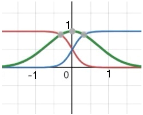
Membership functions are the basic concept in fuzzy logic. They convert data into values between 0 and 1, and these values are regarded as fuzzy data. Membership functions are divided into continuous, triangular, and trapezoidal membership functions. In this study, two types of membership functions were used (see and ).
Figure 2. Type A fuzzy membership function.
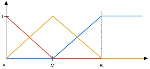
Figure 3. Type B fuzzy membership function.
Lu et al.[Citation24] discussed how the accuracy of machine learning can be improved using fuzzy techniques. Regular data were compared with fuzzy data, and the results indicated that the fuzzy data were more satisfactory. Ordinary fuzzy data were also compared with data that were fuzzified three times, and the results indicated that the latter data were more satisfactory. Sang et al.[Citation25] indicated that a fuzzy logic controller can be used for wheeled mobile robots. This type of control (e.g., the gait pattern controller used in the present study) can be used in a variety of situations. Therefore, the data in the present study were processed using fuzzy logic.
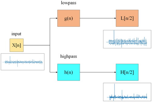
Wavelet transform refers to the use of the oscillatory waveform of a finite-length or fast-decaying mother wavelet to represent a signal. This waveform can be zoomed and panned to correspond to the input signal. Similar to short-time Fourier transform, wavelet transform can be used to analyze time and frequency. However, unlike short-time Fourier transform, whose resolution does not change with time, wavelet transform can help record frequency distributions at different time points or locations. Ji et al.[Citation26] used wavelet transform to classify static and dynamic textures. When wavelet transform was used, more details were observed in an image.[Citation27] These details allowed the difference in textures to be more efficiently identified. Given its characteristics, wavelet transform is typically used for noise removal in image analysis or for the analysis of uneven terrains,[Citation28] which is an element required in the present study.
Wavelet transform is divided into continuous and discrete wavelet transform. In this study, discrete wavelet transform was used. As shown in , a discrete wavelet transform was used as a filter to divide the input signal into two sequences: a high-frequency sequence and a low-frequency sequence. Each sequence constituted half the length of the original signal sequence. The low-frequency sequence was similar to the input signal. When clear changes or noises were detected, they were displayed in the high-frequency sequence. If the first transform did not lead to a satisfying result, transform was performed again using the first low-frequency result so as to obtain the part to be analyzed.
Figure 4. Discrete wavelet transform process.
In this study, trust region policy optimization (TRPO) and advantage actor-critic (A2C) algorithms were used. As mentioned in Section 1, both algorithms were compared with PPO2. In TRPO, the trust region should be introduced first. The function that can maximize the weight is referred to as the trust region. The concept of TRPO is based on that of PPO, and they are both similar. The greatest difference between them is the constraint function. For instance, reward is included in the calculation of PPO, but the constraint function is not included in the objective function in the calculation of TRPO. Generally, TRPO is performed in two steps. First, the function that can maximize the weight is determined. Second, the new weight of the trust region is determined. Finally, these two steps are repeated. Naughton et al.[Citation29] explored software robot control. Several algorithms were used, such as TRPO, PPO, deep deterministic policy gradient (DDPG), twin-delayed DDPG, and soft actor-critic, among which TRPO scored the lowest. However, this was another possible situation. Therefore, in the present study, TRPO was used for the gait pattern control of the robot.
A2C comprises an actor and a critic. It combines the concepts of two types of algorithms, namely, a value-based algorithm (Q-learning) and a policy-based algorithm (policy gradient). The actor is based on the policy gradient, whereas the critic is based on Q-learning. The critic evaluates the actor’s performance of its actions. In each step during the training process, the weights of the actor and critic are immediately updated through a backpropagation process, allowing the two neural networks to learn from previous experiences.
A2C requires two grids to compute the state, namely, Q (the value of the actor) and V (the value of the state). However, unlike the actor-critic, which calculates the reward through its own actor, A2C calculates the reward through the critic. For the actor-critic, the actor calculates the entire reward process to obtain the value. In A2C, the calculation is performed by the actor and estimated by the critic.
Liu et al.[Citation30] used A2C and RL with deep Q-learning. A comparison of the experimental results indicated that A2C was more satisfactory. However, this was not the case in the present study. In other words, Liu et al.[Citation30] focused on dynamic optimization for decision-making, whereas the present study discussed the gait patterns of robots. Thus, this study compared A2C with other algorithms.
3. The proposed method
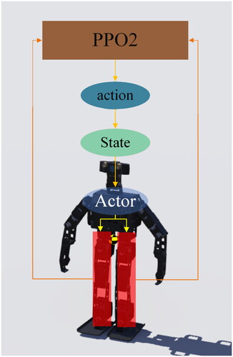
In this study, the PPO2 algorithm was used to control the gait pattern of a humanoid robot (). The two primary factors of this study were the environment and the humanoid robot model. The environment, which was established by a simulator, exhibited an obstacle similar to a five-step staircase, with each step having a different height. The obstacle was also at a fixed distance from the humanoid robot and was fixed to the floor. This prevented it from moving even if the robot collided with it or somehow attempted to affect its position. The humanoid robot was allowed to control its joints through the input angles. It also had an internal measurement unit that allowed obtaining the acceleration in the x, y, and z directions. According to the change in acceleration and the elapsed time, the input data were converted into a moving distance. This essential information provided a decision factor for the actor.
Figure 5. System architecture.
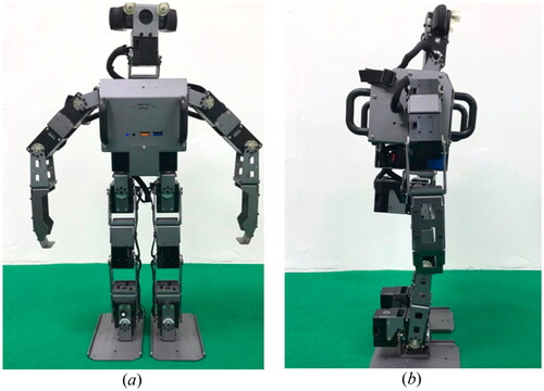
shows the humanoid robot used in this study. The robot’s height was ∼510 mm, its weight was 3.5 kg, and it had 20 degrees of freedom. It had an XM430 actuator, an Intel Core i3 processor, a 128-GB M.2 solid-state drive for the main controller, and an OpenCR for the sub-controller. The internal measurement unit of the robot comprised a three-axis gyroscope, a three-axis accelerometer, and a three-axis magnetometer. Either a Linux (32/64 bits) or Windows (32/64 bits) system could be used as the operating system.
Figure 6. Humanoid robot: (a) front view and (b) side view.
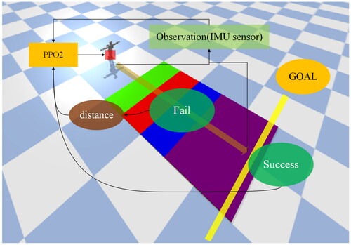
shows the training process of the PPO2 algorithm. As shown in the figure, when the robot failed, it obtained the distance between its position and the finish line. However, when it succeeded, it did not obtain the distance and rather returned a signal of success. As shown in , the six parameters that were used to control the robot’s gait pattern were the legs where the red rectangle is located. In this study, the accelerometer in the IMU sensor is exclusively utilized to extract the acceleration values of the x, y, and z directions from the robot’s body. These values serve as the basis for gait feedback correction during robot locomotion.
Figure 7. State of training with PPO2.
Level 1 is the starting position for the robot, with a height of 0 cm. In levels 2–5, the heights of each color are different. The height of the green level is 0.5 cm, the height of the red level is 0.35 cm, the height of the blue level is 0.25 cm, and the height of the purple level is 0.45 cm, as shown in . This terrain is the main experimental field in this study. shows the training parameters that were used to control the gait pattern. Changes in the lower part of the robot’s body were scrutinized to allow the robot to adapt to uneven terrains. During the gait pattern training, one-time parameters were left unchanged. A training session was then divided into several segments to record 128 values, including the acceleration in the x, y, and z directions in a single step.
Figure 8. Staircase with steps of different heights.
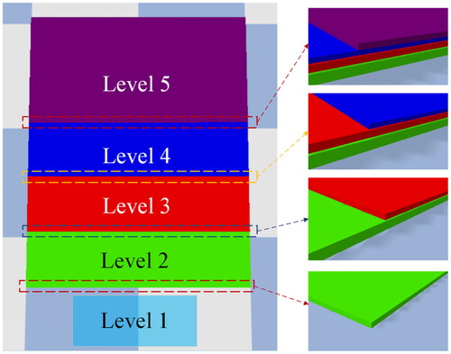
Table 1. Parameters of gait patterns.
In the experiment, relevant gait parameters were also recorded. The parameters of default were recorded and compared with the gait parameters after PPO2 adjustment, as shown in . In this figure, the adjustment of the robot’s gait in real-time with the complex environment can be understood. In the record, if the gait parameters change drastically, it means that unstable conditions are being experienced by the robot and that the existing gait strategy is being optimized. By recording and visualizing changes in gait parameters, how the robot is optimizing its gait during the walking process can be better understood. This will help to improve the stability of the robot’s gait.
Figure 9. Changes of gait parameters when the robot is walking. (a) Gait parameters without PPO controller and (b) Gait parameters when PPO controller is operating.
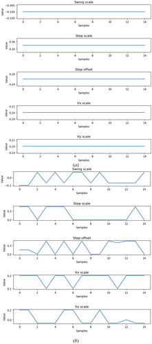
The results were then used a part of the state during the training process. Furthermore, upper and lower limits were set for movement and observation to prevent abnormal readings. This allowed the robot to learn how to change its parameters when encountering uneven terrain and how to eventually make plans to change its gait pattern depending on the learning experience.
shows the parameters of the PPO2 algorithm. The discount factor (γ) was set to 0.99 to allow the robot to effectively learn short-term movement planning. Lambda was used as a factor in the tradeoff between bias and variance in the generalized advantage estimator.[Citation31] In addition, the tradeoff between bias and variance in the execution trajectories of lambda and γ was regarded as a type of reward shaping. Mini batches were used to represent the number of data provided during a training session. The results indicated that they achieved a great distribution of performance, which was suitable for this study. Epoch was used as the duration of replacement and optimization strategies. The entropy coefficient and value function coefficient were mainly used to calculate the loss. The maximum gradient norm and clipping range were used as restraints to prevent inappropriate movements from being made again. Finally, a suitable learning rate was used to facilitate the learning experiment and obtain the optimal movement strategy.
Table 2. Parameters of PPO2.
4. Experimental results
Overall, the experimental results highlighted the training process of the PPO2 algorithm. The experimental video can be accessed in Experimental Video.[Citation32]
4.1. Experimental results on uneven terrain
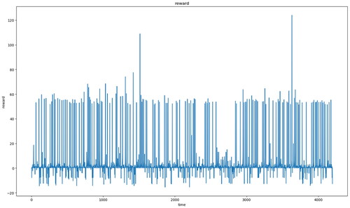
The gait pattern and acceleration of the robot were recorded while it was climbing the stairs. The reward was also defined through code calculation to allow the robot to know the optimal decision. During the training process, the robot selected the values in its joints to obtain its walking trajectory. shows the data for all rewards. If the robot made a wrong decision while walking (e.g., did not walk straight or fell to the ground), the reward value was decreased. As shown in , the highest reward value was >50, indicating that the robot almost climbed all the stairs.
Figure 10. Reward values during the training process.
show the acceleration records of each step when different rewards were provided. These acceleration values are pre-processed and outliers are removed. The reward shown in was the lowest, and the acceleration record was evidently the poorest, particularly in the last part of the figure, implying that the robot fell. By contrast, the reward shown in was the highest, and no noticeable fluctuation was discovered in the acceleration record. Compared with , the acceleration record shown in was obtained after the training process. As can be seen, and slightly differ from each other. This indicates that when the reward value was extremely high, it approached the optimal decision. shows the walking record before the training process, indicating that the robot fell while walking and did not complete the process. However, after training (), the robot completed the process.
Figure 11. Acceleration record when the reward was −32.
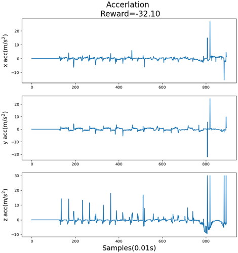
Figure 12. Acceleration record when the reward was 1.5.
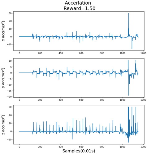
Figure 13. Acceleration record when the reward was 49.
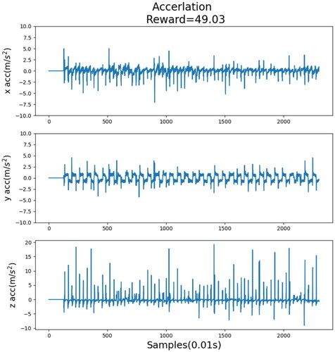
Figure 14. Acceleration record after training.
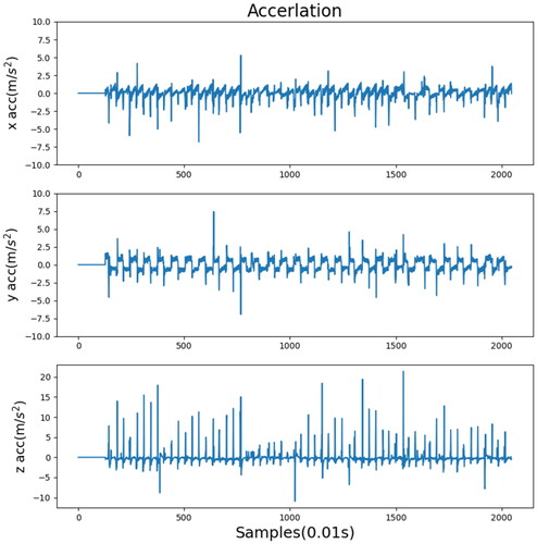
Figure 15. Experimental results before training.
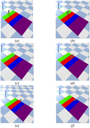
Figure 16. Final results after training.
present comparisons between different algorithms and data processing methods. Each experiment indicated the most suitable method for each algorithm. A comparison of the training data indicated that the standard deviation of each algorithm decreased after wavelet transform. This means that wavelet transform is a method suitable for training a robot’s gait pattern on uneven terrain, hence allowing the robot to walk more stably. However, fuzzification was not suitable for all algorithms. Although the standard deviations of TRPO and A2C decreased, that of PPO2 increased. This indicated that fuzzification was not an appropriate method to use with PPO2 during gait pattern training. The standard deviation of PPO2 with wavelet transform was the lowest, and the training data of the fuzzy membership function (type B) and TRPO were both satisfactory. shows the acceleration record processed by the original sensor, and show the acceleration records processed by wavelet and fuzzification.
Figure 17. Acceleration record in the x, y, and z directions processed by the unprocessed sensor data.
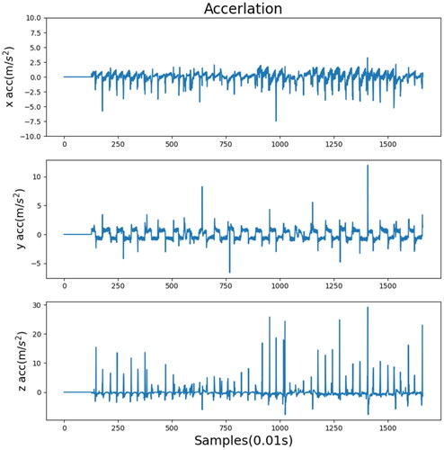
Figure 18. Acceleration record in the x, y, and z directions processed by wavelet transform.
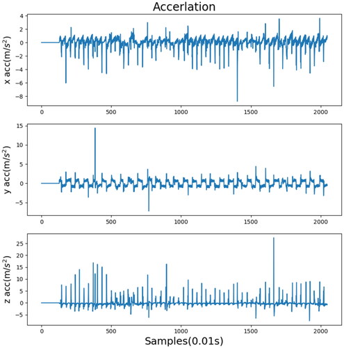
Figure 19. Acceleration record in the x, y, and z directions processed by the type A fuzzy membership function.
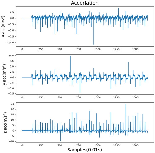
Figure 20. Acceleration record in the x, y, and z directions processed by the type B fuzzy membership function.
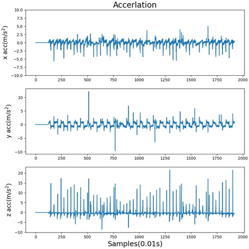
Table 3. Standard deviation of the PPO2 training results.
Table 4. Standard deviation of the TRPO training results.
Table 5. Standard deviation of the A2C training results.
4.2. Experimental results on vibrating terrain
In addition, this study also tested the robot’s ability to walk on a vibrating surface. A random vibrating surface was created in a simulated environment to observe how the humanoid robot would respond in this dynamic environment. During the experiment, the robot had to use its sensors to detect any instability caused by the vibration surface and adjust its gait parameters using DRL model to maintain balance. The purpose of the experiment was to test the robot’s ability to maintain self-balance while walking on unstable surfaces. As shown in , the results of the experiment indicate that the robot was able to walk stably on the vibrating surface without falling.
4.3. Experimental results with impact disturbance
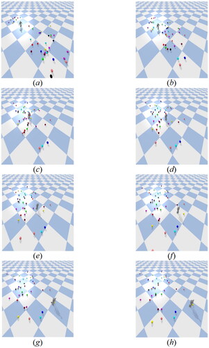
Moreover, the stability of the humanoid robot during walking was tested in the simulator with interference (). In this experiment, the robot walked on a flat surface. During the walking process, many spheres with different speeds surrounded the robot. Due to these interferences, there were many uncertain factors in during walking. The experimental results showed that even with the interferences, the robot was still able to walk stably in such a complicated environment. The primary reason is that the robot utilized DRL model for feedback control, enabling it to adapt its gait strategy and achieve steady walking ability even in the presence of interference, as depicted in .
Figure 21. Experimental results on vibrating terrain.
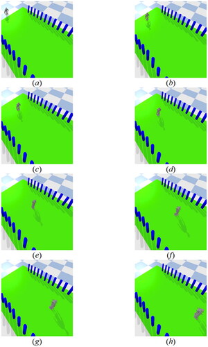
Figure 22. Experimental results with impact disturbance.
4.4. Experimental results on various gait patterns
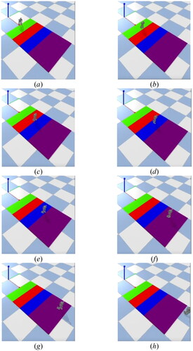
To further test the effectiveness of the proposed method for additional gait patterns, a series of experiments involving more diverse motions were conducted. In addition to the previously tested gait patterns, the robot’s tolerance to external disturbances during walking with new and different gait patterns was also tested. As shown in , the experiments were conducted in a simulated environment where the robot was walked on a vibrating ground and with external impact while turning left and right. While the parameters related to turning left and right were kept constant, the rest of the parameters for the gaits were controlled by the DRL model. The experiment results show that the robot can be walked steadily in complicated environments even when different gaits are used. Furthermore, the effectiveness of the DRL gait feedback controller was also validated in this experiment, demonstrating the robustness of the proposed method. Overall, further evidence of the versatility and effectiveness of the DRL-based gait control method in complex environments was provided by this experiment.
Figure 23. Experiment of additional motion on vibrating terrain (turn left).
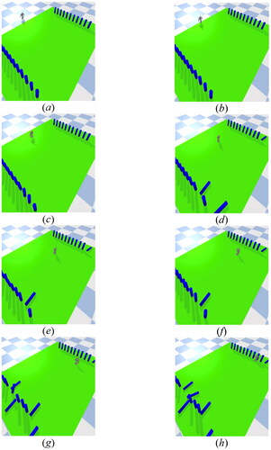
Figure 24. Experiment of additional motion on vibrating terrain (turn right).
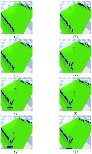
Figure 25. Experiment of additional motion with impact disturbance (turn left).
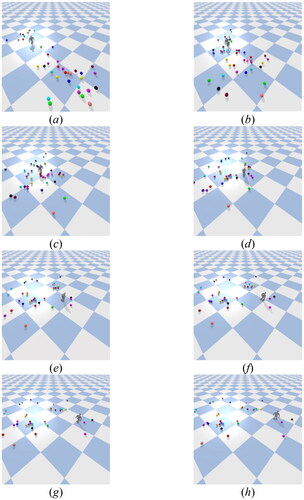
Figure 26. Experiment of additional motion with impact disturbance (turn right).

5. Discussion
Regarding the IMU sensor configuration, the accelerometer used is placed on the trunk of the robot, which is also the position closest to the robot’s center of mass. This position can better represent the robot’s current state. Placing the accelerometer in a position that is too high, too low, or where there is a lot of movement can easily obtain more noise due to the large shaking of the robot during walking, which will cause difficulties in subsequent analysis. Usually, one position is sufficient for the accelerometer, and too much information will increase the complexity of DRL training. This will also make it difficult to converge and affecting the results of DRL. Therefore, the placement and quantity of accelerometers actually affect the efficiency of gait control.
Deep Reinforcement Learning (DRL) is a technique that combines deep learning and reinforcement learning. This technique can be effectively applied to the gait controller of humanoid robots on uneven terrain. Traditional optimization algorithms may face challenges when dealing with highly dynamic and complex problems in this environment. For instance, Particle Swarm Optimization (PSO) and Genetic Algorithms (GA) can perform well on static optimization problems. However, gait control of robots is a highly dynamic and complex problem that requires real-time decision-making or adjustments in response to various circumstances. PSO and GA may be limited in dealing with highly dynamic and uncertain problems. Furthermore, traditional optimization algorithms must optimize an infinite number of cases. Therefore, finding the optimal parameter values may be time-consuming. In the case of gait control of robots, adaptation is required in a constantly changing environment, such as the interference of an uneven surface. DRL can handle such complexity and learn stronger adaptive gait strategies. Therefore, DRL is more appropriate in this study.
Muzio et al.[Citation33] describes a study in which a humanoid robot played soccer with a single opponent in a simulated environment. This study involves many complex issues, such as walking, running, and maintaining balance. The study demonstrates the effectiveness of DRL in solving complex problems of continuous robot control. DRL can also be extended to many issues of robot gait control. Wang et al.[Citation34] proposes a CPG-based hierarchical locomotion controller for modular quadrupedal robots. This method can achieve higher training efficiency. As the advances of DRL technology, robot gait control can gradually catch up with or even surpass human movements and skills, such as running, jumping, and climbing. From the various situations mentioned above, it can be concluded that DRL is helpful in the gait learning of robots in this study.
In this experiment, an accelerometer was used to obtain information about the robot’s motion status. The accelerometer can measure the acceleration of the robot in different directions. The acceleration in the x, y, and z axes can be used to determine whether the robot is moving in the correct direction during gait. Large deviations in x and y acceleration indicate that the direction of movement may not be ideal. Large variations in z-axis acceleration may indicate that the robot has fallen or is in danger of falling. Therefore, the accelerometer is a critical component of the DRL model training process. It provides important information and helps the model make adaptive adjustments to achieve better gait control effects. In addition, the distance traveled by the robot is also taken into consideration. The farther the distance traveled, the better the gait and the higher the reward. With the above analysis, the various gait parameters of the robot during walking, such as Swing scale, Step scale, Step offset, Vx scale, Vy scale, etc., can be adjusted. These parameters can adjust the robot’s gait and make it walk more stably. There are many factors to consider when designing gait parameters, such as the size of different robots, walking speed, walking direction, terrain conditions, load, etc. Therefore, when designing and selecting parameters, these factors should also be taken into consideration to ensure the stability and efficiency of the robot’s walking.
6. Conclusion
Overall, the study results indicated that PPO2, an algorithm based on off-policy and PPO, is recommended for training ROBOTIS OP3 robots. The data used included acceleration records and were obtained by location sensors. RL was also used. The goal of the training sessions was to determine the optimal walking trajectory. A staircase was established on the robot’s path, and the robot was expected to climb this staircase. The robot therefore used different joint values to walk. Unlike in other experiments, the robot obtained different rewards during the process. These rewards were calculated by the acceleration sensor attached under the robot’s feet and by the location sensor attached on the robot’s body. The acceleration values in the x and y directions were then used to calculate whether the robot was moving forward. Subsequently, the acceleration values in the z direction and the robot’s location were used to calculate whether the robot was descending. If the robot walked farther, the reward was increased. However, if the robot selected a less preferable trajectory (e.g., descending), the reward was decreased. After multiple instances of training, the robot eventually adopted the most optimal trajectory. The results also indicated that specific combinations of data processing methods and algorithms allowed the robot’s gait pattern to become more stable. These combinations helped create the perfect trajectory for the robot to walk on uneven terrain. However, future studies should investigate more difficult movements (e.g., ball kicking or performing tasks with PPO2). In addition, if possible, future studies should focus on how robots can navigate on more difficult terrains or perform more types of movements.
Disclosure statement
No potential conflict of interest was reported by the author(s).
Additional information
Funding
References
- Li, J.-M.; Chen, C.-W.; Cheng, T.-H. Motion prediction and robust tracking of a dynamic and temporarily-occluded target by an unmanned aerial vehicle. IEEE Trans. Control Syst. Technol. 2021, 29, 1623–1635. DOI: 10.1109/TCST.2020.3012619.
- Yu, H.; Park, S.; Bayen, A.; Moura, S.; Krstic, M. Reinforcement learning versus PDE backstepping and PI control for congested freeway traffic. IEEE Trans. Control Syst. Technol. 2022, 30, 1595–1611. DOI: 10.1109/TCST.2021.3116796.
- Ye, R.; Chang, M.; Pan, C.-S.; Chiang, C. A.; Gabayno, J. L. High-resolution optical inspection system for fast detection and classification of surface defects. Int. J. Optomechatronics 2018, 12, 1–10. DOI: 10.1080/15599612.2018.1444829.
- Sato, T.; Sakaino, S.; Ohashi, E.; Ohnishi, K. Walking trajectory planning on stairs using virtual slope for biped robots. IEEE Trans. Ind. Electron. 2011, 58, 1385–1396. DOI: 10.1109/TIE.2010.2050753.
- Villarreal, D. J.; Poonawala, H. A.; Gregg, R. D. A robust parameterization of human gait patterns across phase-shifting perturbations. IEEE Trans. Neural Syst. Rehabil. Eng. 2017, 25, 265–278. DOI: 10.1109/TNSRE.2016.2569019.
- Li, Q.; Yu, Z.; Chen, X.; Zhou, Q.; Zhang, W.; Meng, L.; Huang, Q. Contact force/torque control based on viscoelastic model for stable bipedal walking on indefinite uneven terrain. IEEE Trans. Autom. Sci. Eng. 2019, 16, 1627–1639. DOI: 10.1109/TASE.2019.2903564.
- Kyriakoulis, N.; Gasteratos, A. On visuo-inertial fusion for robot pose estimation using hierarchical fuzzy systems. Int. J. Optomechatronics 2012, 6, 17–36. DOI: 10.1080/15599612.2012.664241.
- Wu, L.-F.; Li, T.-H. S. Fuzzy dynamic gait pattern generation for real-time push recovery control of a teen-sized humanoid robot. IEEE Access 2020, 8, 36441–36453. DOI: 10.1109/ACCESS.2020.2975041.
- Dong, S.; Yuan, Z.; Yu, X.; Zhang, J.; Sadiq, M. T.; Zhang, F. On-line gait adjustment for humanoid robot robust walking based on divergence component of motion. IEEE Access 2019, 7, 159507–159518. DOI: 10.1109/ACCESS.2019.2949747.
- Li, T.-H. S.; Kuo, P.-H.; Cheng, C.-H.; Hung, C.-C.; Luan, P.-C.; Chang, C.-H. Sequential sensor fusion-based real-time LSTM gait pattern controller for biped robot. IEEE Sens. J. 2021, 21, 2241–2255. DOI: 10.1109/JSEN.2020.3016968.
- Chen, W.-H.; You, F. Semiclosed greenhouse climate control under uncertainty via machine learning and data-driven robust model predictive control. IEEE Trans. Control Syst. Technol. 2022, 30, 1186–1197. DOI: 10.1109/TCST.2021.3094999.
- Zhang, Z.; Shi, Y.; Yan, W. A novel attitude-tracking control for spacecraft networks with input delays. IEEE Trans. Control Syst. Technol. 2021, 29, 1035–1047. DOI: 10.1109/TCST.2020.2990532.
- Peng, Z.; Wang, J.; Wang, D. Distributed maneuvering of autonomous surface vehicles based on neurodynamic optimization and fuzzy approximation. IEEE Trans. Control Syst. Technol. 2018, 26, 1083–1090. DOI: 10.1109/TCST.2017.2699167.
- Wang, Y.; Wu, X.; Wang, Y.; Zhou, X. Fuzzy logic based feedback control system for the frequency stabilization of external-cavity semiconductor lasers. Int. J. Optomechatronics 2020, 14, 44–52. DOI: 10.1080/15599612.2020.1828516.
- Hwang, K.-S.; Lin, J.-L.; Yeh, K.-H. Learning to adjust and refine gait patterns for a biped robot. IEEE Trans. Syst. Man Cybern. Syst. 2015, 45, 1481–1490. DOI: 10.1109/TSMC.2015.2418321.
- Piperakis, S.; Koskinopoulou, M.; Trahanias, P. Nonlinear state estimation for humanoid robot walking. IEEE Robot. Autom. Lett. 2018, 3, 3347–3354. DOI: 10.1109/LRA.2018.2852788.
- Lin, J.-L.; Hwang, K.-S.; Jiang, W.-C.; Chen, Y.-J. Gait balance and acceleration of a biped robot based on Q-learning. IEEE Access 2016, 4, 2439–2449. DOI: 10.1109/ACCESS.2016.2570255.
- Rakovic, M.; Borovac, B.; Nikolic, M.; Savic, S. Realization of biped walking in unstructured environment using motion primitives. IEEE Trans. Robot. 2014, 30, 1318–1332. DOI: 10.1109/TRO.2014.2344431.
- Yu, Z.; Chen, X.; Huang, Q.; Zhang, W.; Meng, L.; Zhang, W.; Gao, J. Gait planning of omnidirectional walk on inclined ground for biped robots. IEEE Trans. Syst. Man Cybern. Syst. 2016, 46, 888–897. DOI: 10.1109/TSMC.2015.2487240.
- Khan, U. I.; Chen, Z. Natural oscillation gait in humanoid biped locomotion. IEEE Trans. Control Syst. Technol. 2020, 28, 2309–2321. DOI: 10.1109/TCST.2019.2939955.
- Zhao, J.; Iwasaki, T. CPG control for harmonic motion of assistive robot with human motor control identification. IEEE Trans. Control Syst. Technol. 2020, 28, 1323–1336. DOI: 10.1109/TCST.2019.2910160.
- Li, D.; Okhrin, O. DDPG car-following model with real-world human driving experience in CARLA. 2021.
- Schulman, J.; Wolski, F.; Dhariwal, P.; Radford, A.; Klimov, O. Proximal policy optimization algorithms. arXiv. 2017.
- Lu, X.; Meng, L.; Chen, C.; Wang, P. Fuzzy removing redundancy restricted Boltzmann machine: Improving learning speed and classification accuracy. IEEE Trans. Fuzzy Syst. 2019, 28 (10), 1. DOI: 10.1109/TFUZZ.2019.2940415.
- Sang, S.; Wu, H.; Zhao, J.; An, Q. Fuzzy logic control for wheeled mobile robots. In 2009 Sixth International Conference on Fuzzy Systems and Knowledge Discovery; IEEE, 2009; pp. 237–241. DOI: 10.1109/FSKD.2009.241.
- Ji, H.; Yang, X.; Ling, H.; Xu, Y. Wavelet domain multifractal analysis for static and dynamic texture classification. IEEE Trans. Image Process. 2013, 22, 286–299. DOI: 10.1109/TIP.2012.2214040.
- Niimi, T.; Itoh, Y.; Natori, M.; Aoki, Y. Apnea detection method for Cheyne-Stokes respiration analysis on newborn. Int. J. Optomechatronics 2013, 7, 67–82. DOI: 10.1080/15599612.2012.762567.
- Jayasree, V. K.; Shaija, P. J.; Narayanan Nampoori, V. P.; Girijavallabhan, C. P.; Radhakrishnan, P. A simple and novel integrated opto-electronic system for blood volume pulse sensing and heart rate monitoring. Int. J. Optomechatronics 2007, 1, 392–403. DOI: 10.1080/15599610701779325.
- Naughton, N.; Sun, J.; Tekinalp, A.; Parthasarathy, T.; Chowdhary, G.; Gazzola, M. Elastica: A compliant mechanics environment for soft robotic control. IEEE Robot. Autom. Lett. 2021, 6, 3389–3396. DOI: 10.1109/LRA.2021.3063698.
- Liu, Y.; Zhang, D.; Gooi, H. B. Data-driven decision-making strategies for electricity retailers: Deep reinforcement learning approach. CSEE J. Power Energy Syst. 2020, 7. DOI: 10.17775/CSEEJPES.2019.02510.
- Schulman, J.; Moritz, P.; Levine, S.; Jordan, M.; Abbeel, P. High-dimensional continuous control using generalized advantage estimation. 2015.
- Experimental Video. Available at https://youtu.be/kVZY8fkKrPE (accessed May 21, 2023).
- Muzio, A. F.; Maximo, M. R. O. A.; Yoneyama, T. Deep reinforcement learning for humanoid robot dribbling. In 2020 Latin American Robotics Symposium (LARS), 2020 Brazilian Symposium on Robotics (SBR) and 2020 Workshop on Robotics in Education (WRE); IEEE, 2020; pp. 1–6. DOI: 10.1109/LARS/SBR/WRE51543.2020.9307084.
- Wang, J.; Hu, C.; Zhu, Y. CPG-based hierarchical locomotion control for modular quadrupedal robots using deep reinforcement learning. IEEE Robot. Autom. Lett. 2021, 6, 7193–7200. DOI: 10.1109/LRA.2021.3092647.