Abstract
This work is devoted to a new, fast and efficient method of evaluating the number of marginal cells in a non-volatile electrical memory array. This extraction from experimental data is fundamentally an inverse problem. The method proposed here is based on simple cross-correlation functions and de-convoluting operations. With the microelectronics device dimension downscaling, the reliability of non-volatile electrical memory has become crucial and any marginal cell can compromise the functioning of the whole array (containing hundreds of thousands of elementary cells). A specific array called Cell Array Structure Test (CAST) has been developed as a useful characterization tool to statistically study retention and endurance performance with few experimental operations. However, this device cannot easily count the low number of failed cells among hundreds of thousands. That is why we had to develop a mathematical method to extract this major quantity from measurements. This method has been validated on an EEPROM CAST – 0.13 µm technology node, but it is extendable to all memory devices integrated in parallel array and more generally to any electrical measurement done in a similar configuration.
1. Introduction
Currently, the study of non-volatile memory (NVM) reliability is a major industrial challenge because of the rule scaling Citation1. The reliability is directly linked to the quality of the elementary memory device. Obviously, this type of study requires a statistical analysis of the entire memory array to understand and to predict the standard (intrinsic) and singular (extrinsic) elementary component behaviour. The latter is activated by the stress applied on the cell during its life time (erasing, programing, temperature variations, etc.). One of the major issues is the global cost of such studies Citation2. One solution lies in specific device test structures integrated in the same technology as the final product. The aim of such structures is to determine as accurately as possible the quantity of extrinsic and intrinsic cells with the help of few experimental electric characteristics. To exploit the information contained in these characteristics, it is necessary to mathematically process the experimental results.
1.1. Functioning principle of the floating-gate NVM
The elementary electric nonvolatile memory (NVM) device studied here belongs to the family of floating-gate NVM. The basic structure of these devices consists in an MOS transistor structure (TMOS) in which a second gate (usually N-doped polysilicon) is put between the control gate and the channel oxide. This second gate is electrically isolated from the control gate by a stack of different dielectrics and which is called ‘floating gate’ since its electric potential is never set by the operator (it is floating). A comprehensive as well as historical presentation is given in Citation3–5. The device is schematized in . The principle of the device is to modulate the threshold voltage, VT, of a TMOS structure by introducing or removing electric charges from this floating gate. The modulation of the threshold voltage VT, depending on the quantity of electric charge Qfg injected into the gate, follows the classical linear relationship:
(1)
where Cp is the capacitance between the floating gate and control gate determined by the design of the device, and
is the threshold voltage of the virgin cell (no charge in floating gate).
Figure 1. Scheme of a floating gate NVM device (a) and schematic electrical characteristic (b) with different signs of injected charge in the floating gate (Qfg).
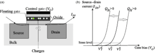
Depending on the amount and sign of injected charges, the trans-characteristic of the transistor (Source-Drain current, denoted by IDS versus the Gate voltage, denoted by VG) will shift, which defines a new threshold voltage: (resp.
) for positive (resp. negative) charges. This fact is schematized in . The difference
is called ‘programming window’ and characterizes the discrimination between the two logical states – called written or erased. The data retention is the time during which the cell can conserve a sufficient programing window. The endurance is the number of write/erase cycles it could undergo before the closure of its programing window.
The injection or removal of electric charges in the floating gate is done by a set of polarization (strongly depending on the cell technology) which allows them to pass through the tunnel oxide. Thus, the latter has a dual role: ensuring the passage of electric charges when programming the cell while blocking them when the cell must keep its logic state (not externally polarized). Because of this particular role, the tunnel oxide is a critical element for the reliability of the device. During normal cell use, charges pass through the oxide and can be trapped inside. These trapped charges can create a conduction path through the oxide which can no longer ensure its dual role.
To finish this section, let us recall the particularity of EEPROM and Flash types. The EEPROM cell has a select transistor in addition to each state transistor. So it has the advantage of the granularity (the access to a single cell in the memory array is easy), however the additional transistor decreases the density. Thus, the EEPROM are generally used in embedded applications (small memory capacity, low power consumption). Flash memories only have the state transistor: the access to one cell is limited while density is high and then they are suitable for mass storage (large memory array).
1.2. Presentation of CAST structure
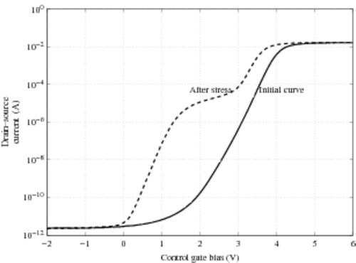
The Cell Array Structure Test (CAST) is a device that has been used for several years to statistically characterize the non-volatile floating gate memory performances Citation6. The device consists of a memory array whose cells are connected in parallel (like NOR architecture with common drain, common source and common control gate). Thus in a single measurement of characteristics (Source-Drain current versus Gate voltage), it is possible to observe a cumulative characteristic of a great number of cells Citation7 even for emerging memory devices such as nano-dot floating gates Citation8. An instance of such a characteristic is presented in , for a CAST before and after electrical stress obtained by successive Write/Erase operations(called cycles). An analysis of the cell density distribution according to their threshold voltage may be carried out with this device. Because the total current of the CAST is the sum of all the currents of each cell (the CAST is a parallel structure), the number of extrinsic cells as well as the distribution of intrinsic ones could be extracted from these two curves. The ‘hump’ of the after-stress characteristics (dashed curve) is typical of the existence of extrinsic cells because these cells impact the CAST characteristic in the low current range. Thus, this device is extremely efficient in pointing out the few cells which lose more average charge. In this article we focus on evaluating the number of these cells because they are the ones which can compromise the whole process yield. The next paragraph emphasizes the difficulty of this evaluation and the fact that it can be considered as an inverse problem.
1.3. Classical exploitation of experimental CAST characteristics
In a virgin CAST, the threshold voltage distribution follows a Gaussian law with a small standard deviation. Indeed, the cells are processed so as to obtain similar physical characteristics. As shown in , the characteristic I(v) looks like a Gaussian cumulative distribution: a quasi zero level assumed to be the measurement of the noise current around 10−12 A, then a rough slope in the range 2--4 V and with current varying from 10−10 A up to 10−2 A, and a plate around 10−2 A due to the saturation current of all the electronic components involved in the measurement (CAST, measurement device, etc.). All cells switch on in a small voltage range that explain the rough slope of the curve. In a standard retention test (a few hundred hours at 150°C), we do not observe any modification of the I(v) characteristic. We can conclude that the VT distribution does not change. On the other hand, a moderate but adequate stress (for instance 100 kilocycles of Write/Erase operations) followed by a standard retention test produces () the following.
| • | An intrinsic phenomenon: a measurable change in VT, of all cells, induced by a charge drop. In practice, this means a CAST characteristic shift. This can be quantified by the evolution of the intrinsic | ||||
| • | An extrinsic phenomenon: the VT of some cells, whose charge loss is greater than the average one, is shifted below the tail of the normal distribution. These cells conduct before the others and change the low values of the CAST current. In practice, it is visible by the apparition of the hump that is typical of the extrinsic cells. This hump is clearly visible in between 0 and 3 V. This can be quantified by the evolution of the extrinsic | ||||
In order to determine the number of those singular or extrinsic cells, responsible for the hump, several classical approaches exist. Historically, as in Citation7,Citation9, it has been shown that the transconductance of an EEPROM CAST can be rebuilt from a cell model transconductance, an assumed Gaussian distribution of VT for intrinsic cells and a singular Dirac distribution for extrinsic ones (assuming that each cell in the CAST has the same trans-characteristic shape as the model one). Moreover, a subtle study of the polarization of the select transistor allows us to extract the standard deviation of the distribution density of the intrinsic cell: the select polarization influencing the transconductance peak of an unitary cell (for details of the structure, see for instance Citation3,Citation4). It is difficult to imagine that this method could be extended for all NVM technology (Flash for instance or emerging structures) because of the particular use of the select transistor, typical of EEPROM technologies.
As previously depicted, the extrinsic cells are the ones responsible for the process yield. They are then the ones we wish to be able to quantify as accurately as possible. In the case of a moderate stress (as illustrated by ), it is not necessary to extract the intrinsic cell density distribution in order to evaluate the number of extrinsic ones. The latter could be found by different inverse resolutions of Gaussian deconvolution, for instance by extraction of statistical parameters Citation7,Citation9 or by a Gaussian deconvolution procedure as classically done in a medical device Citation10,Citation11. In order to avoid the extraction of the intrinsic part of the curve, we have recently proposed two non-computing methods to estimate the number of extrinsic cells in an EEPROM CAST Citation12,Citation13. The first method which is experimental and visual is based on the EMMI technique Citation14. Although it is accurate and reliable, this approach is technically difficult to implement and requires special equipment. The second method, based on a renormalization of the CAST transconductance, only works well if the threshold voltage offset (between extrinsic and intrinsic cells) is high enough. On the other hand, it requires fine-tuning of the polarization of the select transistor. Logically this approach only works for memory cells using select and state transistors.
In this article we propose a new method to calculate the number of extrinsic cells, based on deconvoluting cross-correlation functions. The major interest lies in its simplicity of implementation. Indeed, it only requires knowledge of two experimental characteristics of a CAST and a single cell characteristic model whose shape and amplitude have no notable effect on the resolution. At minima, the virgin CAST characteristics can be used as a cell model characteristic. Also, both current and transconductance characteristics can be used thanks to the linearity of the relations. The computational part is immediately performed on a standard Personal Computer.
In the first part of this article, we will expound the theoretical approach. Second, we will explicit the numerical implementation. Finally, we will analyse the validity of the method using two examples of EEPROM CAST and we will compare them with previously published results.
2. Theoretical approach
This section is divided into two parts. First, we will explain the approach (hypothesis and mathematical relations) which enables us to model the experimental CAST drain current I(v) versus gate voltage v by using a convolution product Citation7,Citation9. Second, we will expose mathematical tools needed to extract the number of extrinsic cells.
2.1. Modelling of the current of the CAST
The measured current of the CAST, versus the gate voltage, is denoted by I(v). ip(v) represents the current of the pth cell, for a voltage v, and N0 the total number of cells. It results in (1st Kirchoff's law)
(2)
The cells contained in a CAST are physically very close: same fabrication process, same wafer localization and same neighbourhood in the array Citation15. That is why it is classically assumed that each cell characteristic has the same shape. The characteristics of all cells are obtained by just shifting a single characteristic model Citation7,Citation9. This current model is denoted by i0(v). Thus, if Vp is the threshold voltage of the cell p, we obtain
(3)
and the relation (2) becomes
(4)
Experimentally, the voltage v varies from the minimal value (v = V0) up to the maximal one (v = Vm). The appropriate voltage range requires that all Vp be comprised between V0 and Vm. If δv is the experimental voltage resolution, the value Nv of significant increment of v is
. Thus n(Vk), the cell density, is defined by the number of cells whose threshold voltage is in [Vk; Vk + δV[. This latter is equal to n(Vk)δV. The appropriate experimental values of V0 and Vm also imply that
(5)
Obviously, the sum of this function is the total number of cells in the CAST:
(6)
and so the relation (4) becomes
(7)
Considering δV is very small compared to Vm − V0, the sum of Equation (7) can be approximated as a continuous sum and so (replacing Vk by VT and using conventional notation)
(8)
The relation (6) becomes
(9)
Because of relation (5), the sum in relation (8) can be extended from −∞ to +∞. So we obtain a convolution product denoted by ⊙:
(10)
2.2. Link with the experimental quantities
In this case of moderate stress, measurements on isolated cells show that the trans-characteristic shape (particularly the under threshold slope) is not significantly affected Citation13. So, in the model described in the previous section, the same i0(v) shape can be used for both virgin and stressed (cycled) CAST. Indeed, it is the basic classical assumption that describes the CAST current as a convolution.
The quantities I(v) are measured for both damaged and virgin CAST. The current i0(v) must be assumed. The most intuitive way is to measure the characteristic of a single cell made in the same technology as the CAST and to assume that this characteristic is a good estimation of i0(v). One of the difficulties is that the electric behaviour of a cell depends on its environment. When alone, a given cell does not have the same characteristics as when in the CAST. Indeed, the access resistances, seen from the cell, are not the same at all. So i0(v) is neither theoretically nor experimentally accurately accessible quantity.
The experimental increment of gate voltage δV has to verify the conditions exposed in the previous section. It can eventually be constrained if we want to work with transconductance: the latter is numerically computed from current measurement by a finite difference.
2.3. Issues of the direct deconvolution procedure
Assuming a ‘reasonable’ cell density distribution n(v) (Gaussian with low standard deviation, for instance, for the intrinsic part due to the very high number of identical cells), and a rough estimation of i0 (for instance staircase shaped), the direct computation of I(v) by relation (10) gives a realistic result. Indeed, with two lightly different i0 (slope varying) currents, the convolution with a peaked Gaussian distribution gives quite the same result. It confirms that the direct computation by a convolution product is not very sensitive to the shape of i0(v) as observed in Citation7,Citation9. More generally, two different functions, convoluted with the same function, could give exactly the same result. This aspect is well known in electrostatics, for instance, when using Green's functions Citation16.
In order to determine n(v), particularly in the distribution tails (low VT values), we have to inverse this product. This inverse operation of the convolution product, often called ‘deconvolution’ is theoretically simple. Indeed, one of the important mathematical properties of the convolution product lies in the properties of its Fourier transform. The convolution product becomes an algebric product in Fourier space. Numerically, this operation is classical and there are a lot of efficient deconvolution algorithms (for instance, Citation17,Citation18 based on polynomial division). Thus, if I(v) is experimentally obtained and i0 numerically or experimentally known, the deconvolution of relation (10) should give directly the density n(v).
In practice, as in many inverse problems, the deconvolution of relation (10) is ill-posed for two major reasons:
| i. | The choice of the experimental discretization δv of the voltage range is a delicate balance between two effects. If it is too large, the passage from relation (7) to (8) is no longer valid. If it is too small, the sampling of the number of cells becomes too thin compared to the number of cells, particularly in the distribution tails. | ||||
| ii. | Unlike the direct problem, the deconvolution is very sensitive to the i0(v) shape (particularly in the cell VT range). More generally, it is well-known, particularly in electrodynamic scattering (see, for instance Citation16,Citation19,Citation20), that several couples of two functions give similar results for convolution. This is so critical because of the incorrect estimation of i0(v). | ||||
Moreover, because of the huge difference between the order of magnitude of currents in the CAST in the intrinsic part (around 1 mA) and the extrinsic part (around 1 µA), due to the very small numbers of extrinsic cells, it is difficult to imagine the extraction of the quantity n(v) in a single and same procedure. Because we are interested in the extrinsic population, we separate the contributions of the intrinsic cells on the one hand and the extrinsic ones on the other hand. This is equivalent to define two zones on the curve as a function of voltage and treat only the considered extrinsic part. This helps simplifying and stabilizing the inverse problem. Finally, we have to say that the simple deconvolution of relation (10) cannot suffice to extract usable n(v). Thus, the aim of our method is to minimize the influence of the model function i0 when deconvoluting, particularly the typical hump of the damaged CAST characteristic. This stabilization is principally achieved by using cross-correlation product between experimental quantities.
2.4. Cross-correlation relations
We denote by the correlation product of the two generic functions f and g. Classically,
is named ‘cross-correlation’ between f and g and it is defined as follows:
(11)
We denote the physical quantities related to the cycled CAST (resp. virgin CAST) by a script c (resp. v). We consider the cross-correlations between Iv, Ic and i0 characteristics.
denotes the cross-correlation between Iv and Ic,
the cross-correlation between Ic and i0, and so on.
Since the variables of integration in the cross-correlation and convolution products are independent, we can use the Fubini theorem. The order of integration can be switched. By a meticulous and laborious but straightforward calculation, we get
(12)
By substracting the quantities
,
and
, we obtain the two essential relations of our numerical method:
(13)
and
(14)
Experimental characteristics and an i0 model make it possible to compute the cross-correlation function 𝒳. Deconvoluting relation (12), (13) or (14) gives the quantities nc, nv and the difference
The interesting values of Dn(v) are the positive ones, because in the extrinsic domain of the CAST, nc > nv.
3. Numerical implementation
The extraction process of the extrinsic cell number is described as follows.
| i. | We choose the ‘intrinsic’ sense current Ii that defines the ‘intrinsic’ threshold voltage | ||||
| ii. | The characteristic Ic (cycled CAST) is shifted to match Iv (virgin CAST) so that they have the same | ||||
| iii. | The functions | ||||
| iv. | The quantity Dn(v) = nc(v) − nv(v) is obtained by the deconvolution of | ||||
| v. | We denote by e+(v) the function equal to | ||||
| vi. | To verify, we can re-build the cycled CAST drain current | ||||
4. Results
4.1. Experimental details
As previously described the aim of the experimental stress is to make some extrinsic cells appear, avoiding a complete degradation of the CAST. So the stress operation is moderate. Measurements have been performed on 8.2 K cells and 209 K cells EEPROM CAST, which is an NOR parallel complete structure (all cells have common source, drain, gate, bulk and select contacts), in 0.13 µm technology. The programing operations are performed under standard conditions (amplitude: 14.5 V, rise time: 1 ms, total pulse length: 3 ms and select transistor gate voltage, Vslt = 16 V) for both write and erase operations. The cells are cycled 105 times which is a moderate and sufficient stress. The reading operation is performed with a polarization VDS = 0.1 V and Vslt = 5 V. The reading operations are performed on Agilent 4156 C precision semi-conductor parameter analyser. Each measurement is repeated around five times with less than 0.5% dispersion. Indeed, the measurement precision is not a critical parameter. The whole procedure occurs at room temperature.
Let us remark that these experimental conditions are just an indication because our purpose is to determine the extrinsic cell number and not to relate it to experimental conditions.
4.2. Influence of the cell model current
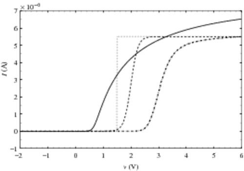
We compare the results given by four different cell-model currents. The first one, denoted by i01, is the one obtained by an EEPROM model computation code Citation21. The second one, i02, is a sigmoid function defined by the following equation:
(17)
The third one, i03, is a ‘stair case’-shaped current. And finally, the fourth one is the Iv(v) characteristics (renormalized for reconstruction). The four models are normalized so that they have the same order of magnitude in the voltage range, as shown in . This normalization allows the current model to be shifted with respect to the threshold voltage
and then to rebuild the damaged CAST characteristics.
4.2.1. 8.2 K cells EEPROM CAST
Here, the numerical voltage increment is fixed at δv = 10−2 V for all characteristics. It is the experimental increment, reproduced in simulated characteristics i0. In all figures, we do not represent all experimental points for better visibility of the curves, but all computations are done with δv = 10−2 V.
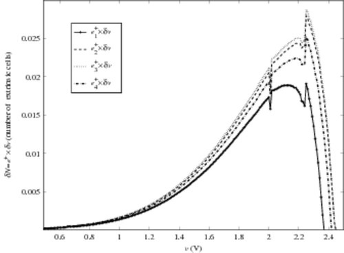
The quantity δN(v) = e+(v)δv, proportional to the cell density distribution (e+(v)), is plotted in for each cell model current. The four curve shapes are similar. We observe that for the two rough models (i02 and i03) the e+ maximum is greater than the one obtained with the finest models (i01 and i04). By integrating these functions in the range of voltage presented here, we obtain the four values evaluating extrinsic cells.
(18)
We observe a difference of around 30% between
and
or
, while
is roughly between these extreme values. Note that a sharp deconvolution based on relationship (10) does not provide any usable numerical results, whatever the current model. Moreover, they are completely inconsistent with one another.
The differences observed – in and result (18) – between each evaluation are only due to the difference of the shape of i0. As a matter of fact, due to the normalization of the quantity that includes N0, the maximum value of i0 does not impact the result for e+. The crucial parameter seems to be the ratio between the slope pm of the cell-model curve i0 and the slope pc of the Ic curve, around the Ie current. We observe that the evaluation of Ne increases with the slope of the current model. Indeed, we have
Since the CAST current is the sum of each cell current, it is clear that pm cannot be greater than pc. The problem is that our model is built on a ‘safe’ (even for i04) cell model and we do not have access to extrinsic cell characteristics.
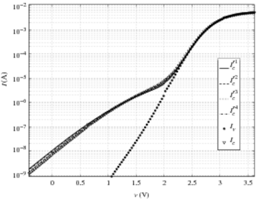
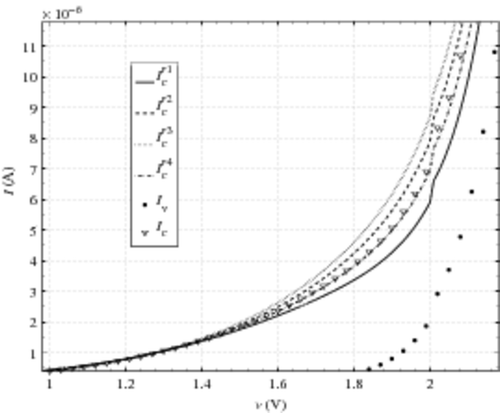
Finally, we plot the four reconstructed characteristics ,
,
,
(obtained, respectively, with the four model currents) in . The reconstruction of the hump of the damaged CAST is satisfactory on a logarithmic scale. This reconstruction validates the assumption according to which the cell current model is the same for all the cells in the CAST and that the difference observed between the sub-threshold voltage slope of damaged CAST and the one of virgin CAST is only due to the variation of the cell density n(v) in this voltage range, and not to a variation of single cell current.
For a more quantitative approach, we plot in the same characteristics on a linear scale and focus on the beginning of the hump [1 V; 2.2 V]. We observe that under-estimates Ic, while
and
over estimate Ic. This observation is coherent with the values of
,
and
. The greatest relative difference between
and Ic is around 20% for v ∼ 1.9 V while it is around 30% for
and
for v ∼ 2 V.
completely matches the damaged CAST characteristics. It seems to be the best reconstruction. However, this result has to be considered in the light that the normalization of i04 is arbitrary. This normalisation impacts the reconstruction (16). Only the comparison with the three other reconstructions is relevant.
4.2.2. 209 K cells EEPROM CAST
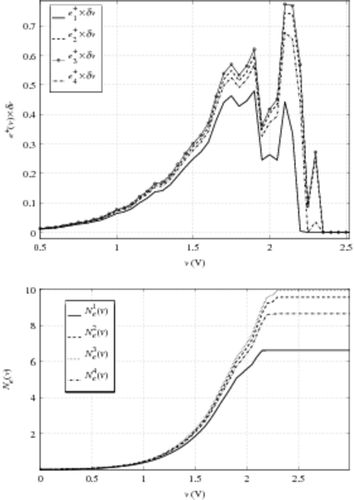
Another influence of the cell model current shape can appear at the higher truncature of e+ (for v ∼ VTi). As a matter of fact, in the area where Ic and Iv are very close, it is very difficult to find a discriminating criterion between extrinsic and intrinsic cells. Numerically, this discrimination problem can be observed. In , we plot e+(v) × δv (as done in ) versus v obtained with the help of the four model currents, in the case of an 209 K cell EEPROM CAST, using the same technology. We also plot the quantity
representing the number of extrinsic cells with VT < v. Here we use a voltage increment δv = 0.05 V for a better lisibility of these curves. These results are also consistent with the ones obtained for the standard increment δv = 0.01 V.
For v < 2 V, we observe the same qualitative evolution as for the 8.2 K CAST. For values v < 1.9 V, the differences between the four evaluations of Ne(v) are not really significant. And even at v = 2 V, the four different extractions yield results ranging from less than one cell. So, we can conclude that this method is not affected by the shape of the current model, in the voltage range suitable for determining extrinsic cell numbers.
For v > 2 V, a sharp peak appears for ,
and
. This peak strongly impacts the result on Ne evaluated on the whole voltage range, as shown in . This marginal behaviour is induced by three simultaneous phenomena:
| • | In this instance, VTe ∼ 2 V. Thus around this voltage value, we reach the limit between extrinsic and intrinsic CAST behaviour. This is fundamentally linked to our arbitrary limit when defining e+. | ||||
| • | The ratio between the slopes of Ic and i0 has a significant effect: the greatest peak is observed for i03 (‘stair-case’ current). | ||||
| • | The voltage sample influences the characteristic shift. This point is developed in the next section. | ||||
4.3. Influence of the voltage sample
The construction of relation (10) implies that the voltage increment δv has to be small compared to the voltage scale. In this section we analyse the influence of the value δv on the numerical results for e+ and Ne. The instances presented are performed on the previous 8.2 K cell CAST damaged characteristics, with i0 = i01. In , we plot e+(v)δv and Ne(v) for different voltage increments δv. It appears naturally that e+(v)δv increases with δv, roughly in the same proportion. The results when determining Ne are the following: with δv = 0.15 V, Ne ∼ 1.5 while for δv = 0.12 V, Ne ∼ 1.7. Moreover, there is a stability ‘window’ for δv from 0.02 V up to 0.12 V.
Figure 8. Top e+ versus v evolution for different voltage sample δv, bottom Ne(v) versus δv. Curve legend is the same in the two figures.
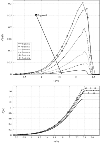
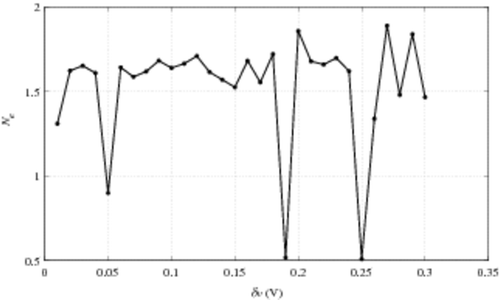
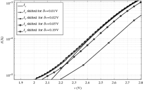
To understand the odd behaviour of Ne versus δv, we plot the quantity Ne versus δv in a very large range of δv. Results are presented in . The stability δv-window is observed around Ne ∼ 1.6 for δv values going from 0.02 V up to 0.2 V, with a very singular exception at δv = 0.05 V in the range of δv < 0.15 V (experimentally used and compatible with the hypothesis leading to relation (10)). This phenomenon can be interpreted as an influence of the accuracy of the initial curve shift in our process. The occurrence of such a problem increases with δv, as shown in . To illustrate this, we plot the shifted characteristics Ic for different δv in . We observe that for both δv = 0.05 V and δv = 0.19 V, Ic does not coincide with Iv: they are both under the Iv characteristic, which is contrary to our expectations. This can be explained by the voltage shift which is defined within δv range. As around Ie and Ii the characteristic slopes are quite pronounced, a huge relative difference between the currents can appear in a very tiny voltage interval. Let us remark that this small mismatch appears for a range voltage greater than 2.2 V (9). It should be remembered that the range of v < 2 V is the one of interest, as previously discussed in Section 4.2.2. To avoid this ‘shift artefact’, it should be interesting to finely interpolate the characteristics around Ie and Ii. This approach transfers, indeed, the problem to the characteristic slopes, that is to say to the CAST transconductance. This quantity is not directly obtained by measurements but by numerical computations based on finite difference. In the instances presented here, the noise makes the derivative approximation by finite difference very unstable. Thus, the problem is not completely resolved. The current solution lies in a balance between an adapted δv and an adequate initial shift.
4.4. Comparison with existing results
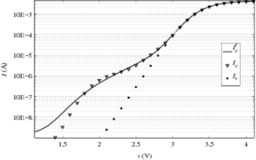
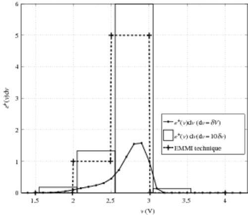
To finish, we test the deconvolution method whose existing results have already been published. A method using EMMI technique of visualization has been recently proposed to evaluate the number of extrinsic cells in a CAST Citation12. First, we test our deconvolution on I-V characteristics used for the EMMI technique. In , we plot the two characteristics of same CAST (when virgin and when cycled) and the current. The model current i0 is computed with the help of an already calibrated EEPROM model. The reconstruction of the ‘hump’ of the cycled characteristics is satisfying. Thus, we compare the number of extrinsic cells evaluated by our deconvolution and the number found with the EMMI technique. For these measurements, in the original paper Citation12, we describe one extrinsic cell with VT around 2 V and five extrinsic cells with VT around 2.8 V. To evaluate the results given by the ‘deconvolution’ method, the extracted e+(v) function is plotted in . The function e+ is classically plotted. We also represent the sum of e+dv in each interval of 0.5 V with a ‘bar’ graph. The latter immediately enables us to see the number of extrinsic cells in a given voltage interval. Here, we find one extrinsic cell with VT between 2 and 2.5 V and six extrinsic cells with VT between 2.5 and 3 V. These results are completely compatible with the ones announced using the EMMI technique. With the visualization method, when voltage is near the intrinsic threshold voltage of the CAST, the one-by-one counting method becomes difficult. Thus, the evaluation of one single extrinsic cell is not easy.
5. Conclusion
In this article, we presented a new fast and robust method to quantify the extrinsic cells of a CAST. It only requires a cell characteristic model and the measurement of CAST electrical characteristics before and after stress. After presenting the theoretical basis and numerical implementation, we conducted a sensitivity analysis of various parameters (current model and step voltage) on the provided result. One of the conclusions of this part is the slight influence of the model current on the result. This method has been confirmed using a 0.13 µm EEPROM STMicroelectronics technology, on different samples and successfully compared with previous results.
The major advantages of this method lie in the three following points:
| • | The final result (number of extrinsic cell) is almost independent from the model current. | ||||
| • | It requires only a few simple experimental measurements: knowledge of virgin and stressed CAST characteristics (the virgin CAST characteristic is a sufficient cell model). | ||||
| • | It can be applied to any device placed in a parallel architecture. | ||||
References
- A. Allan, 2007 ITRS ORTC, 12/5 MakuhariJapan ITRS Public Conference, 2007.
- Bestory, C, Marc, F, and Levi, H, 2007. Statistical analysis during the reliability simulation, Microelectr. Reliability 47 (9--11) (2007), pp. 1353–1357.
- Brown, WD, and Brewer, JE, 1998. Nonvolatile Semiconductor Memory Technology: A Comprehensive Guide to Understanding and Using NVSM Devices. New York: Wiley, IEEE Press; 1998.
- Brown, WD, and Brewer, JE, 2008. Nonvolatile Memory Technologies with Emphasis on Flash: A Comprehensive Guide to Understanding and Using Flash Memory Devices. New York: IEEE Press Series on Microelectronic Systems, Wiley, IEEE Press; 2008.
- Cappelletti, P, Golla, C, Olivo, P, and Zanoni, E, 1999. Flash Memories. Dordrecht: Kluwer Academic Publishers; 1999.
- Cappelletti, F, Bez, R, Cantarelli, D, Nahmad, D, and Ravazzi, L, 1997. CAST: An electrical stress test to monitor single bit failures in FLASH-EEPROM structures, Microelectr. Reliability 37 (1997), pp. 473–481.
- Pio, F, and Gomiero, E, 2000. Cell array structure test in EEPROM reliability assessment at an early process development stage, Microelectr. Reliability 40 (2000), pp. 719–722.
- Monzio, C, Ielmini, D, Spinelli, AS, Lacaita, AL, and Gerardi, C, 2004. Study of nanocrystal memory reliability by CAST structures, Solid-State Electr. 48 (9) (2004), pp. 1497–1502.
- Pio, F, and Gomiero, E, 2001. Select transistor modulated cell array structure test application in EEPROM process reliability, Solid-State Electr. 45 (2001), pp. 1279–1291.
- Ulmer, W, and Kaissi, W, 2003. The inverse problem of a Gaussian convolution and its application to the finite size of the measurement chambers/detectors in photon and proton dosimetry, Phys. Med. Biol. 48 (2003), pp. 707–727.
- Ulmer, W, 2010. Inverse problem of linear combination of Gaussian convolution kernels (deconvolution) and some applications to proton/photon dosimetry and image processing, Inverse Probl. 26 (2010), pp. 085002.1–085002.26.
- Le Roux, C, Lopez, L, Firiti, A, Ogier, JL, Lalande, F, Laffont, R, and Micolau, G, 2007. A new method to quantify retention-failed cells of an EEPROM CAST, Microelectr. Reliability 47 (2007), pp. 1609–1613.
- Le Roux, C, Lopez, L, Firiti, A, Ogier, JL, Lalande, F, Laffont, R, and Micolau, G, 2008. An experimental method allowing quantifying and localizing failed cells of an EEPROM CAST after a retention test, Solid-State Electr. 52 (10) (2008), pp. 1550–1554.
- Kolzer, J, Boit, C, Dallmann, A, Deboy, G, Otto, J, and Weinmann, D, 1992. Quantitative emission microscopy, J. Appl. Phys. 70 (1992), pp. 23–41.
- Aziza, H, Plantier, J, Portal, JM, Reliaud, C, and Ginez, O, 2008. "A novel Flash EEPROM Diagnosis Methodology based on I-V Signatures Extraction". In: Proceedings of the NVMTS'08. California: Pacific Grove; 2008. pp. 105–110.
- Jackson, JD, 1975. Classical Electrodynamics. New York: Wiley; 1975.
- Morhac, M, and Matousek, V, 2005. Exact algorithm of multidimensional circulant deconvolution, Appl. Math. Comput. 164 (1) (2005), pp. 155–166.
- Oppenheim, AV, and Schafer, RW, 1989. Discrete-Time Signal Processing. Englewood Cliffs, NJ: Prentice-Hall; 1989.
- Chew, WC, and Wang, YM, 1990. Reconstruction of two-dimensional permittivity distribution using the distorted Born iterative method, IEEE Trans. Med. Imag. 9 (1990), pp. 218–225.
- Saillard, M, Vincent, P, and Micolau, G, 2000. Reconstruction of buried objects surrounded by small inhomogeneities, J. Inverse Probl. 16 (2000), pp. 1195–1208.
- Laffont, R, Masson, P, Bernardini, S, Bouchakour, R, and Mirabel, JM, 2003. A new floating gate compact model applied to flash memory cell, J. Non-Crystal. Solids 322 (1--3) (2003), pp. 250–255.
