
 ?Mathematical formulae have been encoded as MathML and are displayed in this HTML version using MathJax in order to improve their display. Uncheck the box to turn MathJax off. This feature requires Javascript. Click on a formula to zoom.
ABSTRACT
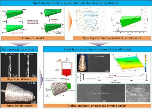
Metal droplet-based 3D printing provides unique advantages for fabricating micro complex parts. Especially, assisted by soluble support, structures with high-quality inner surfaces can be directly printed without post-processing, which is very promising for the fabrication of waveguides and antenna horns. Here, a spatially distributed equidistant helical deposition strategy with only one-step positioning was proposed to improve the inner surface quality of the parts, and a five-axis motion stage was designed for matching its motion planning. The influence mechanisms of key process parameters on the forming quality were investigated. The droplet positioning errors, the aggregation behaviour, and the hole-defects formation on sloping surfaces were analyzed. As a proof-of-concept, a horn-structured tube was directly printed via the proposed printing method, which possessed both high-quality cavity surfaces and high density. This work paves the route towards the efficient additive manufacturing of metal tubes with high-quality inner surfaces.
GRAPHICAL ABSTRACT
1. Introduction
Metal droplet-based 3D printing is an emerging additive manufacturing and green manufacturing technology (Murr and Johnson Citation2017; Qi et al. Citation2020; Visser et al. Citation2015) that enables quick and inexpensive fabrication of parts with arbitrary and custom-tailored shapes (Cao and Miyamoto Citation2006; Chao et al. Citation2012; Fang, Chandra, and Park Citation2008; Goh et al. Citation2016; Tan, Tran, and Chua Citation2016; Yingxue, Shengdong, and Chengsong Citation2004). This is highly dependent on its ability to directly and efficiently print metal structures that deliver not only the customisable design concept but also the surface quality and/or mechanical properties for practical applications. Moreover, this technology offers high material recovery rates and no need for special raw materials or expensive equipment (Dou et al. Citation2021). Therefore, it is a very promising processing route for numerous applications, such as bioengineering (Kalkal et al. Citation2021; Sakurada et al. Citation2020), electronics(Merrow et al. Citation2021; Murr Citation2016; Saengchairat, Tran, and Chua Citation2017), heterogeneous parts(Huang et al. Citation2020; Plog et al. Citation2020), and micro components (Lee et al. Citation2008; Luo et al. Citation2017a).
In this technology, aluminum and copper alloys are potential raw materials for printing. Among them, research into the printing of lightweight metallic materials represented by aluminum alloys is promising for applications. For example, aluminum waveguide parts, offer the advantages of lighter mass, better heat resistance, superior strength than plastics, wider application areas, and better environmental suitability. However, achieving stable ejection and printing of aluminum alloys is challenging. The high surface tension and corrosiveness of molten aluminum alloys make stable jetting difficult, and the structure and material requirements for nozzles are strict. The study to exceed these challenges will also guide the implementation of printing other metallic materials. Moreover, there are functional parts that require copper alloys for printing, such as copper waveguides. For such higher melting point metals, it is a great challenge to improve the high-temperature printing capability and stability of the printing system. Apart from these single raw materials, multi-material printing is receiving extensive attention with reporting on 3D printed electronics (Lewis and Ahn Citation2015). Amongst others, prominent research on the multi-material direct digital manufacturing of 3D structural electronics (Church et al. Citation2017) and the notable report on 3D printing of multi-material electronics (Goh et al. Citation2021) lay the foundation for future breakthroughs in this technology towards printing multi-material functional parts.
However, in this technology, for all printing raw materials, uniform metal droplets are used as the manufacturing cells, and the printed parts usually exhibit uneven surface morphology, which cannot satisfy the high surface accuracy requirements of some devices, such as microwave elements, MEMS devices, etc. Therefore, numerous researches aiming to improve the surface quality of printed parts have been conducted during the past two decades. Extensive studies have been performed on optimising process parameters, such as scanning step and interlayer offset in metal droplet printing (Qi et al. Citation2012; Qi et al. Citation2015), and slice thickness during the pileup processes (Yanpu Citation2016). Moreover, reducing the size of the metal droplet has gradually become another research hotspot, such as upgrading the traditional pneumatic ejection device (Amirzadeh and Chandra Citation2010; Amirzadeh, Raessi, and Chandra Citation2013; Amirzadeh Goghari and Chandra Citation2007), developing a new uniform metal droplet on-demand generator (Luo et al. Citation2016). Furthermore, due to the heat accumulation effect during metal droplets continuously depositing (Liu et al. Citation2021), it is easy to produce thermal deformation and deposition error accumulation, resulting in the reduction of surface quality and dimensional accuracy of the printed samples. As a result, alternate droplet printing method was presented to suppress thermal deformation and local printing defects (Luo et al. Citation2017b). However, uneven surfaces are easily formed due to the natural curvature of metal droplets, and especially for the inner surfaces of the printed parts, whose quality is difficult to be improved by post-processing. Therefore, direct printing parts with high-quality and complex inner surfaces remains a significant challenge.
According to the most recent work, soluble core assisted metal droplet printing by point-by-point deposition has been proposed as an effective strategy to directly fabricate tubes with high-quality inner surface (Yi et al. Citation2019b). Although the proposed printing trajectory based on the positioning of each droplet position can effectively determine droplet deposition location and improve positioning accuracy. However, its printing efficiency is still relatively low and unable to flexibly adapt to the complex droplet impingement conditions when printing variable cross-section metal parts (Qi et al. Citation2020). When adopting this droplet printing strategy, each droplet must be accurately positioned and then deposited, thus the corresponding droplet scanning path consists of uniform interrupted linear motion segments. This will inevitably lead to discontinuous velocities and accelerations at the positioning of each droplet, which limits the acquisition of the desired geometry and productivity. Current researches on the scanning path planning mainly focus on presenting modular path planning solution (Michel et al. Citation2019), new path planning method based on stress orientations (Xia, Lin, and Ma Citation2020) and curved layer (Chakraborty, Aneesh Reddy, and Roy Choudhury Citation2008; Xie et al. Citation2020), etc. However, these solutions still cannot effectively address the abovementioned challenges.
For metal droplet printing, the printed part surface will spontaneously form a scalloped shape driven by the surface tension of molten droplets (Luo et al. Citation2017b). This inherent surface is non-ideal in the application cases when high inner surface quality is required but difficult to be significantly improved through post-processing. Based on this, inspired by the soluble cores in precision casting and the equidistant conical helix in the turning process, this paper developed a helical printing trajectory planning strategy for the continuous deposition of aluminium droplets on the support surface with variable sections. As a result, the scientific motivation for this work is to apply the key ideas of traditional manufacturing processes to metal droplet-based 3D printing, which enables the direct fabrication of metallic tubular parts with variable cross-sections and high inner surface quality. To this end, a further adjustment of the deposition device and the corresponding printing trajectory is essential to efficiently print metal tubes with both varying cross-sections and high-quality inner surfaces. A five-axis directional printing deposition platform was developed to match this printing trajectory. Following that, the influence mechanisms of deposition distance and deposition frequency on the forming quality were studied. Finally, the effectiveness of the proposed printing trajectory was verified via conducting the printing experiment of an aluminum horn-structured tube. This research paves the way to directly and efficiently print metal tubes with high-quality inner surfaces via the metal droplet printing technique.
2. Experimental setup
2.1. Experimental system and technological processes
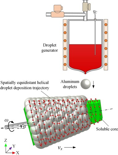
As shown in (a), a special-purpose experimental system was developed to achieve soluble support-assisted support printing by rotary deposition of molten metal (aluminum) droplets. It mainly consists of a five-axis motion subsystem (three translating axes X, Y, Z, and two rotating axes R, S), a uniform metal droplet generation subsystem, and a low-oxygen environment control subsystem. By elaborately adjusting the ejection of uniform metal droplets and the trajectory of the five-axis motion platform, metal droplets can be continuously deposited onto the outer surfaces of soluble support. The nozzle used in this paper is ∼800 μm in diameter and usually generates droplets with a diameter of 1.2∼2 times the nozzle diameter (Chao et al. Citation2012; Fang, Chandra, and Park Citation2008). The droplet diameter generated in this work is ∼1200 μm. During the processes of metal droplet printing, the oxygen and water vapour contents of the working environment should be kept under ∼10 PPM (part per million), controlled by the low oxygen environment control subsystem. Some more detailed operating principle of this system can be found in our previous work (Yi et al. Citation2019b).
Figure 1. (a) Schematic diagram of the experimental system; (b) Process flow diagram for fabricating metal horn-structured tube via depositing metal droplets on a soluble support.
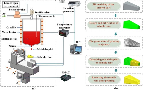
(b) presents the process flow for fabricating a horn-structured tube via rotationally depositing metal droplets onto a soluble support. First, a 3D model of the printed part was developed through commercial CAD software. Then, a soluble support could be designed and fabricated based on the dimensions and shape of the inner cavity of the printed part. Herein, water-soluble gypsum, commonly used in precision casting, was used as the main matrix material for the soluble support (Yi et al. Citation2019b). Afterward, the detailed printing trajectory was generated according to the corresponding planning principle. Uniform molten metal droplets were continuously deposited onto the outer surfaces of the soluble support following the specified printing trajectory. Finally, the soluble support was dissolved and decomposed by water, and a horn-structured tube with higher inner surface quality was fabricated.
2.2. Characterisation
The microstructures and morphologies of the printed samples were characterised by scanning electron microscopy (SEM, VEGA3, TESCAN), and optical microscope (OM, MM-400, Nikon), respectively. The phase characterisation of the silver coating of soluble support was conducted using X-ray diffraction (XRD, X’Pert PRO MPD, Panalytical). Surface flatness was measured with a coordinate measuring machine (Leitz PMM-C 12.10.7). The relative densities of the printed samples were measured using the Archimedes immersion method (ASTM standard C373-18).
3. Modelling of metal droplet trajectory based on spatially distributed helix
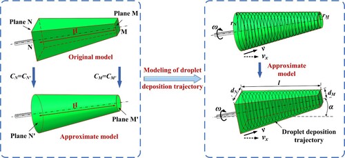
Embedded printing assisted by the soluble support can be achieved by coordinated matching of support motion and droplet ejection. Specifically, generated metal droplets are deposited continuously on the surface of the soluble support which rotates circumferentially and feeds axially. The soluble support is then dissolved after completing forming, and a metal horn-structured tube with high inner surface quality can be obtained. Herein, this paper proposed a droplet deposition trajectory based on an equidistant conical helix to achieve both high intracavity surface quality and high forming efficiency. This strategy requires only one positioning, i.e. for the first droplet, to achieve continuous print formation. This innovation facilitates improved printing efficiency and accuracy without repeated positioning of each droplet. Since repeated positioning both reduces printing efficiency and may accumulate positioning errors. As shown in , the prismatic soluble support was equivalently processed as a circular table to facilitate the planning of droplet trajectory. It is crucial to ensure that both geometric models possess the same height, perimeter of the bottom and top planes (i.e. planes M and M’, planes N and N’). This equivalent model could ensure that the required deposition area was equal without affecting trajectory planning.
Figure 2. Schematic diagram of the modelling of droplet deposition trajectory based on spatially distributed helix.
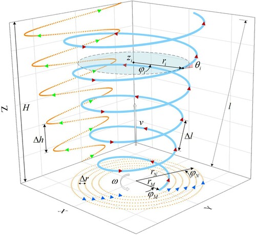
The droplet trajectory needed to be spatially equidistant along the conical surface to ensure a good and consistent bonding quality between adjacent droplets. For this purpose, this paper developed a spatially equidistant helix model based on the Archimedean spiral. As shown in , according to the definition of Archimedean spiral, it is a trajectory resulting from a moving point leaving a fixed point at a uniform speed while rotating around that fixed point with a fixed angular velocity. Its trajectory is shown as an Archimedean spiral in the projection of the X-Y plane in . On this basis, this moving point is also given a uniform motion along the axial direction. Its trajectory in the vertical direction is shown in the projection of the X-Z plane in . Every time the helix rotates around the Z-axis, its elongation in the axial direction is equal, which means the lead Δh is equal. Eventually, the motion in the three directions can be superimposed to form a spatially equidistant helical trajectory, as shown in .
Figure 3. Schematic diagram of spatially equidistant helix.
The parametric equations of this helix in Cartesian coordinates are defined as:
(1)
(1) where the parameter
is the polar angle. According to the geometry of soluble support, the polar angles at the starting point (N) and ending point (M) are defined respectively as:
(2)
(2) where
and
are the radii of helix at point M and N, which are converted from the perimeter of top and bottom planes of the soluble support (
). In Equation (1), r is the radius that varies uniformly with the polar angle and is defined as follows:
(3)
(3) a and Δr are the radius elongation per radian and per turn, respectively, defined as follows:
(4)
(4)
(5)
(5) where n is the number of helical turns required for printing, defined as follows:
(6)
(6) where l is the length of conical generatrix, i.e. the surface length of the soluble support, obtained from the following equation.
(7)
(7) where H is the height of helix, i.e. the height of the soluble support. Δl is the height increase per turn and also the deposition interval of droplets, which is defined as follows:
(8)
(8) Where
and
are the spreading factor and initial diameter of the aluminum droplet, respectively. In Equation (1), b is the height increase per radian, defined as follows:
(9)
(9) where Δh is the lead of helix and follows the following equation.
(10)
(10) The parameters used in this computational model are shown in . Specific parameters of the helical droplet trajectory were determined based on the soluble support geometry parameters and printing process parameters. According to previous studies (Qi et al. Citation2020; Yi et al. Citation2019a), the spreading factor
is approximately ∼1.4 when aluminum droplets are deposited on the inclined support surface. Substituting the parameters, eventually, the set of parametric equations for helical droplet trajectory was calculated as follows:
(11)
(11) The droplet deposition trajectory is shown in by calculating the abovementioned model. Where the red dots represent the aluminum droplet deposition locations and the silver balls characterise the deposited droplets. The droplets are uniformly distributed along the spiral trajectory with a deposition interval of Δl. The starting and ending points of droplet deposition are located at points N and M, respectively.
Figure 4. Schematic diagram of helical droplet trajectory.
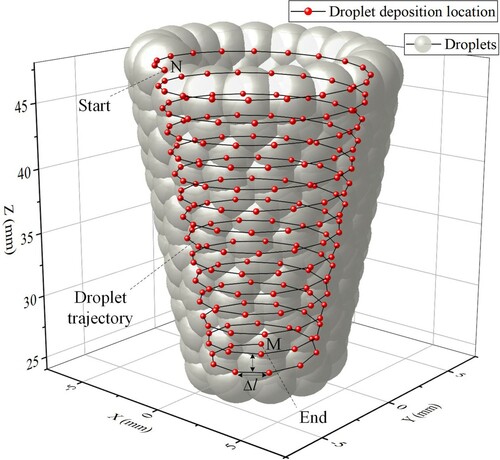
Table 1. Soluble support geometry parameters and printing process parameters.
After the spatially equidistant helix model is developed, the motion speed of the platform needs to be decomposed and planned to ensure that the droplets are deposited uniformly along the trajectory. During printing, the motion stage S-axis needs to be deflected by an angle α calculated based on the geometry of the support (shown in ) to maintain the deposited upper surface horizontal. Through rapid circumferential rotation and axial feeding, aluminum droplets are continuously deposited on the soluble support and finally completely encapsulate it. Therefore, it is crucial to match the circumferential rotation velocity and axial feed velocity of the soluble support. Based on this, the uniform motion of deposition point along the helical trajectory is decomposed into an angular velocity rotating around the axis and an axial feed velocity v, and the print execution velocity vx of the platform in the x-direction, defined as follows:
(12)
(12)
(13)
(13)
(14)
(14) where α is the deflection angle required to perform printing, α = arccos (H/l), f is the droplet deposition frequency, and
is the helix lift angle. As shown in , the helix lift angle at Zi is
, and its calculation follows the following equation:
(15)
(15) According to the definition of velocity:
(16)
(16)
(17)
(17) where
is the differentiation of angular velocity
corresponding to time
, and
is the differentiation of axial velocity v corresponding to time
. Integrate them separately as follows:
(18)
(18)
(19)
(19) where the angular velocity is coordinated in time with the axial velocity. The integration yields a time function concerning the polar angle
as follows:
(20)
(20) Moreover, the total forming time T depends on the helical droplet trajectory length L, deposition interval
, and frequency f, as defined below.
(21)
(21) where the helical droplet trajectory length L follows the following formula:
(22)
(22) Integrating over Equation (22) and simplifying gives:
(23)
(23) Integrating Equations (18) and (19), the total forming time obtained satisfies the following equation.
(24)
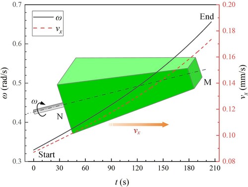
(24) Finally, the parameters were substituted into the abovementioned model for calculation, and the matching relationship between angular velocity and axial velocity versus time was obtained, as shown in . It took only ∼206 s to complete one layer of printing for this part, a nearly ∼2-fold improvement in forming efficiency compared to the discontinuous printing strategy that took ∼400 s.
Figure 5. Platform motion planning: angular and axial velocities versus time.
4. Results and discussion
Continuous deposition print forming of metal parts is a complicated process that is influenced by many factors. In addition to the substrate movement itself, the location and frequency of droplet deposition also affect the deposition accuracy. Therefore, the abovementioned technical issues must first be investigated. Through studying the influence mechanisms of droplet deposition distance and frequency on forming quality, the reasonable selection range of each factor was explored. It could provide guidance for the subsequent droplet deposition forming of micro-metal parts.
4.1. Selective basis of droplet deposition distance
During metal droplet deposition, accurate control of the droplet deposition position on the substrate is a precondition for quality forming. And the droplet deposition distance, i.e. the vertical standoff distance between the nozzle and substrate, is the main factor affecting the positioning. A large droplet deposition distance triggers significant lateral dispersion, which leads to a large deposition position error of the metal droplets and deteriorates the part quality. Therefore, a reasonable selection of droplet deposition distance to suppress its lateral dispersion during ejection deposition is a prerequisite for effective control of metal droplet deposition positioning accuracy.
As shown in (a), P0 is an ideal deposition location for metal droplets, while P1 is the actual deposition location. In the process of metal droplet deposition, since the droplet possessed an initial velocity v2 in lateral flight, the distance of droplet in lateral motion gradually increased with the droplet deposition distance Hs increasing. The droplet deviated from the ideal deposition position when deposited on the substrate, resulting in a deposition error. When the value of ΔP is assumed to be less than the diameter of the deposited droplets in this study, it is considered to be an acceptable deposition error. Due to the transverse partial velocity v2 of the droplet is small and has certain randomness, it is difficult to measure accurately. A suitable selection range of Hs was determined to suppress the lateral dispersion distance of droplet deposition to effectively control the droplet deposition position error. According to (a), the smaller is the deposition distance Hs, the shorter is the lateral dispersion distance of the droplet, and therefore the higher is the deposition accuracy. However, Hs should not be too small, because there exists a breakup length L in the process of breaking the metal jet into microdroplets. If the selected Hs<L, the metal jet cannot break normally, resulting in the failure of droplet generation. Therefore, Hs should not only avoid being too large, but also meet the minimum distance requirement for droplet breakup. The breakup length L can be predicted by the following equations (Grant and Middleman Citation1966):
(25)
(25)
(26)
(26)
(27)
(27) where Dj is the metal jet diameter; C is a dimensionless parameter regarding the amplitude of jet disturbance, which is 1.5∼1.7 in metal droplet-based 3D printing according to experimental study (Chao et al. Citation2012); We and Re are the Weber number and Reynolds number, respectively, determined by material density ρ, jet velocity vj, jet diameter Dj, surface tension σ and viscosity μ. Typical experimental conditions are ρ = 2780 kg·m−3, vj = 0.5∼1.0 m·s−1, Dj = 0.8 mm, σ ∼0.9 N·m−1, μ ∼1.3 × 10⁻³ Pa·s. Then the breakup length L can be predicted to be about 0.95∼2.14 mm by calculation. Therefore, the minimum droplet deposition distance Hs should be at least greater than ∼2.14 mm.
Figure 6. (a) Schematic diagram of droplet deposition deviation; (b–e) Printed pillars morphology and extracted profiles at different deposition distances (Hs = 20, 15, 10, 5 mm).
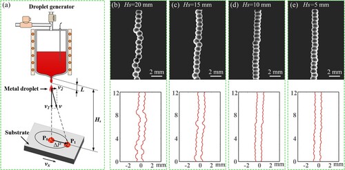
A series of pillar printing experiments were conducted to determine the appropriate deposition distance Hs. As shown in (b), when the Hs was 20 mm, the droplet positioning showed a significant deviation due to the presence of uncertain lateral initial velocity. As shown in (c), when Hs was gradually reduced to 15 mm, the positioning accuracy of the droplet improved, with only a slight deviation in the horizontal direction. Further, as shown in (d) and (e), when the Hs gradually continued to decrease to 5∼10 mm, the lateral deviation of the droplet was almost negligible, and the positioning accuracy improved significantly. Therefore, 5∼10 mm is considered as a suitable droplet deposition distance range with acceptable deposition accuracy to avoid the positioning error caused by too large Hs and the failure of droplet generation due to too small Hs.
4.2. Selective basis of deposition frequency
The deposition frequency of metal droplets is a significant factor affecting the printing quality and productivity in the metal droplet 3D printing technology. In the directional printing of metal droplets, the deposition frequency mainly affects the heat and mass flux of the deposited layer. As the deposition frequency increases, the heat accumulation effect in the deposited layer gradually tends to be significant (Liu et al. Citation2021), which leads to the overmelt phenomenon. While the deposition frequency is too small, the mechanical properties of printed parts deteriorate due to the poor quality of metallurgical bonding between adjacent droplets (Fang, Chandra, and Park Citation2009). Herein, a thermal conduction model described by the correspondence between the thermal energy input Ein and the thermal energy output Eout was proposed to determine a suitable deposition frequency. According to a previous study conducted by (Fang, Chandra, and Park Citation2007), Ein and Eout can be expressed as follows:
(28)
(28)
(29)
(29) where Dd and f are the initial droplet diameter and deposition frequency, respectively; Td, Tsub and Tsurf are the initial temperature of droplet, substrate temperature, and surface temperature of the deposited layer respectively, which can be obtained by the temperature collection module; ρ, Cd, k and L are the density, specific heat, thermal conductivity, and latent heat, respectively; h is the height of the deposited layer; Rf is the thermal contact resistance between the deposited layer and the soluble support, which can be assumed to be ∼10−3 m2·K·W−1 according to a previous study conducted by (Loulou, Artyukhin, and Bardon Citation1999); S is the average cross-section area of the deposited layer. For typical experimental conditions: Dd = 1200 μm, Td = 1023 K, Tsub = 300 K, Tsurf∼650 K, ρ = 2780 kg·m−3, Cd = 875 J·kg−1·K−1, k = 121 W·m−1·K−1, L = 390,000 J·kg−1, h ∼ 10−3 m, Rf ∼10−3 m2·K·W−1, S∼10−5 m2.
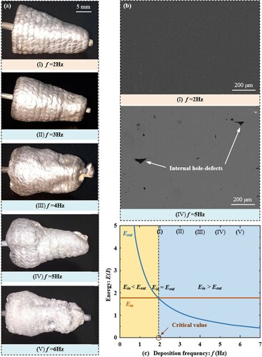
shows the results of experimental and theoretical calculations at different frequencies. Since the gypsum support is a heat insulation material with slow heat dissipation, the calculation results show that the critical value of heat accumulation occurred at a lower value ∼2 Hz ((c)), which was consistent with the experimental phenomenon ((a)). When f = 2 Hz ((a-I)), the solidification morphology of droplets on the surface of the horn-structured tube printed through the helical trajectory was relatively regular, and it possessed high internal quality ((b-I)). Whereas, when f = 3 Hz ((a-II)), excessive melting gradually appeared on the surface of the printed tube. As the deposition frequency increased, the heat accumulation effect was enhanced. And the cooling rate of the droplets after deposition decreased, leading to an increase of the residual liquid phase in the deposition area. Under the effect of surface tension, a random aggregation phenomenon occurred between droplets that did not solidify in time. As shown in (a-III∼Ⅴ), when the deposition frequency was increased above 3 Hz, the degree of fusion between adjacent droplets was too high to maintain the regular shape of droplets, leading to forming failure. The residual metal liquid on the surface layer underwent deflected flow, resulting in incomplete forming and even hole-defects. Also, irregular droplet deposition behaviour at high deposition frequency could trigger internal hole-defects ((b-IV)). According to the abovementioned experimental study, the deposition frequency should be guaranteed to be around 2 Hz, while the maximum should not exceed 3 Hz, which was consistent with the theoretical results.
Figure 7. (a) Horn-structured tubes printed at deposition frequencies f = 2, 3, 4, 5, 6 Hz; Internal qualities of the tubes printed at deposition frequencies f = 2 and 5 Hz; (c) Comparison between thermal energy input and output in the deposited layer at different deposition frequencies.
To further understand the experimental phenomena, a numerical model based on the volume of fluid (VOF) method was developed to analyze the droplet aggregation process during deposition. As shown in (a), the numerical model consists of two molten droplets and a substrate with a computational domain size of 2.8 × 2 × 2 mm. The detailed development and validation of the model were reported in our previous work (Yi et al. Citation2019a). The dimensionless time parameter t* is defined as follows:
(30)
(30) where vd is the droplet deposition velocity, set to 0.8 m·s−1, and t represents the real time in simulations. Other parameters and boundary conditions of the simulation model were kept consistent with the abovementioned experimental conditions.
Figure 8. (a) Computation domain and boundary conditions of the numerical model; (b) Comparison between footprints when f = 1 and 5 Hz; (c) Agglomeration process of adjacent droplets; (d) Formation of hole-defects on an inclined surface.
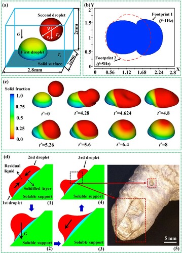
(b) shows the comparison of droplet footprints on the substrate surface when the deposition frequency was 1 and 5 Hz. The footprints of the two droplets could be clearly identified when the deposition frequency was 1 Hz. While, when the deposition frequency was 5 Hz, the two droplets almost fused together to form a large footprint. (c) shows the time series of agglomeration of two droplets printed with a frequency of 5 Hz. It can be seen that due to the high deposition frequency, the second droplet started to deposit at t* = 0 before the first droplet was completely solidified. Then from t* = 4.28 to t* = 4.8, a partial remelting of the first droplet under the influence of the second one could be observed. Eventually, at t* = 8, the two droplets almost completely fused together under surface tension, which coincided with the experimental phenomenon shown in (a): as the deposition frequency increased (from f = 2 Hz to f = 6 Hz), the heat accumulation led to an increase in the residual liquid phase and remelting; subsequently, the droplets randomly aggregated with each other and the bonding profile of droplets gradually dissolved.
Hole-defects would be formed when the deposition frequency was too high, and the formation mechanism is shown in (d). Since the actual deposition process the soluble support sometimes provided an inclined deposition surface for the droplets. When a droplet was deposited on the inclined surface, the droplet continued to flow along the substrate surface for a short time due to gravity and kinetic energy. As shown in (d-1) only a thin solidification layer was formed at the bottom. While the upper remelted liquid phase fused with the residual liquid phase under surface tension. Afterward, the fused liquid phase continued to flow deflected along the substrate surface by gravity and residual kinetic energy ((d-2)), resulting in the overall deflection of melt downward along the slope ((d-3)). When the deflection of previously fused melt was large, the deposited third droplet could not lap sufficiently with the previous one. Hole-defects then formed, as shown in (d-4). The accumulation of such defects would lead to the formation of macroscopic crater defects, which eventually directly deteriorated the forming quality, and the experimental phenomenon is shown in (d-5).
4.3. Continuous printing assisted by embedded soluble support
In this paper, printing experiments of variable cross-sectional horn-structured tubes were conducted using the proposed strategy of soluble support-assisted printing via spatially distributed helix trajectory. The printing principle is shown in , in which the dots represent the aluminum droplet deposition locations and the silver balls characterise the deposited droplets.
Figure 9. Schematic of soluble support-assisted printing via spatially distributed helix trajectory.
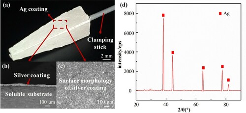
Previously optimised process parameters (f = 2 Hz, Hs = 5 mm) were used for the printing experiment. Due to the poor wettability between the molten aluminum alloy and the support material, uncontrollable phenomena such as bouncing will occur when the aluminum alloy droplets are deposited directly on its surface. This behaviour will reduce the forming accuracy of printed parts, or even directly lead to printing failure. Generally, the wettability between metallic materials is relatively good. Therefore, a metallic transition layer was used to improve the wettability between the molten metal and heterogeneous matrix (Ko et al. Citation2013). As shown in (a), a continuous dense silver coating with good adhesion and thermal conductivity was prepared on the surface of the water-soluble gypsum support using screen printing and sintering techniques. The surface of the prepared silver coating was smooth ((b)), and the thickness was about 50 μm ((c)). (d) shows the X-ray diffraction (XRD) pattern of the coating surface, and the XRD result shows that the main element of the coating was silver. When aluminum alloy droplets were deposited on the surface of silver coating, the pegging effect can eliminate the bounce of metal droplets (Qi et al. Citation2020). The detailed development of silver coatings and initial dynamic behaviour of aluminum alloy droplet impact was reported in our previous work (Yi et al. Citation2018).
Figure 10. (a) A typical soluble support with Ag coating; (b) SEM image of the cross-section of soluble support; (c) Optical micrograph of Ag coating surface; (d) XRD pattern of the Ag coating.
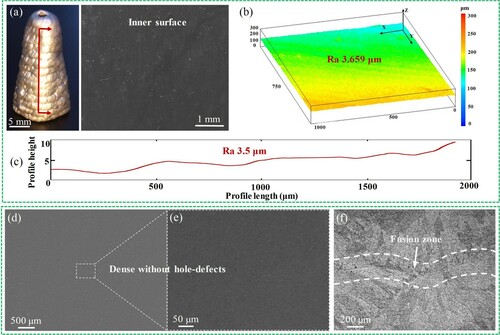
The spatially distributed helix trajectory and optimised process parameters were used to perform the soluble support-assisted horn-structured aluminum tube printing experiment. (a) shows the aluminum tube after removal of the water-soluble support. The actual forming height is slightly higher than the theoretical value to allow sufficient machining allowance, and the error margin is ∼9.17%. (b) shows the detailed inner surface texture of the tube with a measured roughness of ∼Ra 3.659 μm. As shown in (c), the roughness of the inner surface profile was further measured as ∼Ra 3.5 μm using an optical profiler. These characterisations indicate that the printed tube possesses a smooth inner surface with an inner surface roughness value of only ∼0.3% of the droplet diameter. The measured inner surface flatness was ∼11.7 μm. The density measured with the standard Archimedes method was about ∼97%. The above results indicate that the inner surface of the printed tube possesses high inner surface quality and can meet the basic usage requirements without secondary machining. Moreover, the forming efficiency of the helical printing strategy without repeated positioning was increased by nearly ∼2 times compared to the discontinuous printing method. Simultaneously, the printed tube featured good internal quality. As shown in (d, e), the interior of the tube was dense and free of hole-defects. Better remelting metallurgical bonding occurred at the droplet contact interface as shown in (f). In the fusion zone, it was mainly composed of unoriented equiaxed grains, while the interior of the droplet away from the fusion zone was mainly composed of columnar grains with obvious growth direction. The presence of shared grains crossing the contact interface could be seen in the fusion zone, and the interfacial bonding mode was mostly intracrystalline, which allowed the printed part to obtain favourable mechanical strength. The experimental results verified the effectiveness and superiority of the droplet printing strategy.
Figure 11. (a) Horn-structured aluminum tube for soluble support-assisted printing using spatially distributed helix trajectory; (b) 3D confocal microscope image of the inner surface of the tube; (c) Profile roughness of the inner surface of the tube; (d, e) Internal quality of the tube; (f) Interfacial bonding of the tube.
5. Conclusions
In this study, a spatially distributed helix-based printing trajectory was proposed to achieve continuous deposition of metal droplets on soluble support with variable cross-sections. To fulfil the motion planning requirements, an experimental system was further developed, including a five-axis motion platform and a positioning control device. Based on the analysis of the geometric features of the printed part, an equivalent geometric model was developed for droplet trajectory planning. A spatially distributed equidistant helical printing strategy was proposed based on the Archimedean spiral, and the corresponding droplet deposition trajectory model was developed. The influence mechanisms of key process parameters, i.e. deposition distance and frequency, on the printing quality were further investigated. This work opens up new prospects for the direct and efficient fabrication of micro metal parts with high-quality inner surfaces. The main conclusion can be drawn as follows:
Since droplet generation was usually accompanied by lateral instability, the random positioning error of droplets increased with the deposition distance. The desirable deposition distance range should be set as 5∼10 mm.
As the deposition frequency increased, heat accumulation behaviour would occur when the heat input exceeds output, while ideal heat transfer conditions could be obtained at a deposition frequency under ∼2 Hz. At high frequency deposition, random aggregation occurred between droplets driven by surface tension, which eventually leaded to forming failure.
The proposed printing strategy enabled high-efficiency printing with continuous deposition with only one positioning. It not only reduced the accumulation of errors that might result from repeated positioning of the printhead, but also saved excess positioning time and improved forming efficiency by ∼2 times.
The internal quality of the sample was uniform without obvious defects, and its density reached ∼97%. The average roughness of the inner surface reached ∼Ra 3.659 μm, which is only ∼0.3% of the droplet diameter.
In summary, this research provides a potential technological route for the rapid preparation of lightweight, thin-walled functional components such as radars, antennas, waveguides, microfluidic channels, etc. Furthermore, in future research work, smaller droplets are still needed to improve the printing resolution to achieve direct printing of functional components with more complex and fine structures. Moreover, new type soluble support materials with higher surface quality, such as ceramic cores, need to be developed for obtaining higher internal surface quality.
Disclosure statement
No potential conflict of interest was reported by the author(s).
Additional information
Funding
Notes on contributors

Hao Yi
Hao Yi is an Assistant Professor in the College of Mechanical Engineering at Chongqing University, China. He is serving as Associate Editor for Journal of Mechanical Engineering Science (Proc. IMech E Part C), Experimental Techniques, Micro & Nano Letters, and Editorial Board Member for Frontiers in Materials, Advances in Materials Science and Engineering, Materials Science-Medziagotyra, etc. His main research interests focus on 3D Printing and Additive Manufacturing, Green Manufacturing, Production Research, etc.
Jun Luo
Jun Luo is an Associate Professor at School of Mechanical Engineering, Northwestern Polytechnical University. His research interests include package technology, metal droplet disposition, jet breakup simulation, droplet charging and deflection, droplet based solid freeform fabrication.

Menglin Liu
Menglin Liu is currently a M.S. degree student in the College of Mechanical and Vehicle Engineering, Chongqing University, Chongqing, China. His research activities are mainly focused on metal additive manufacturing and 3D printing.

Huajun Cao
Huajun Cao is a Full Professor in the College of Mechanical and Vehicle Engineering, Chongqing University, China. His research interests mainly include the green manufacturing and remanufacturing, green and intelligent factory, and high-speed dry machining technology and equipment.

Lehua Qi
Lehua Qi is a Full Professor at School of Mechanical Engineering, Northwestern Polytechnical University. Her research interests include micro-manufacturing based on metal droplet deposition technology, manufacturing technology and forming mechanism of metal matrix composites and image recognition for the C/C composites.
References
- Amirzadeh, A., and S. Chandra. 2010. “Small Droplet Formation in a Pneumatic Drop-on-Demand Generator: Experiments and Analysis.” Experimental Thermal and Fluid Science 34 (8): 1488–1497.
- Amirzadeh, A., M. Raessi, and S. Chandra. 2013. “Producing Molten Metal Droplets Smaller Than the Nozzle Diameter Using a Pneumatic Drop-on-Demand Generator.” Experimental Thermal and Fluid Science 47: 26–33.
- Amirzadeh Goghari, A., and S. Chandra. 2007. “Producing Droplets Smaller Than the Nozzle Diameter by Using a Pneumatic Drop-on-Demand Droplet Generator.” Experiments in Fluids 44 (1): 105–114.
- Cao, W., and Y. Miyamoto. 2006. “Freeform Fabrication of Aluminum Parts by Direct Deposition of Molten Aluminum.” Journal of Materials Processing Technology 173 (2): 209–212.
- Chakraborty, D., B. Aneesh Reddy, and A. Roy Choudhury. 2008. “Extruder Path Generation for Curved Layer Fused Deposition Modeling.” Computer-Aided Design 40 (2): 235–243.
- Chao, Y. P., L. H. Qi, Y. Xiao, J. Luo, and J. M. Zhou. 2012. “Manufacturing of Micro Thin-Walled Metal Parts by Micro-Droplet Deposition.” Journal of Materials Processing Technology 212 (2): 484–491.
- Church, K. H., N. B. Crane, P. I. Deffenbaugh, T. P. Ketterl, C. G. Neff, P. B. Nesbitt, J. T. Nussbaum, et al. 2017. “Multimaterial and Multilayer Direct Digital Manufacturing of 3-d Structural Microwave Electronics.” Proceedings of the Ieee 105 (4): 688–701.
- Dou, Y. B., J. Luo, L. H. Qi, H. C. Lian, and X. H. Hou. 2021. “Generation Mechanism and Suppression Method of Landing Error of two Successively Deposited Metal Droplets Caused by Coalescence and Solidification.” International Journal of Heat and Mass Transfer 172: 12.
- Fang, M., S. Chandra, and C. B. Park. 2007. “Experiments on Remelting and Solidification of Molten Metal Droplets Deposited in Vertical Columns.” Journal of Manufacturing Science and Engineering 129 (2): 311–318.
- Fang, M., S. Chandra, and C. B. Park. 2008. “Building Three-Dimensional Objects by Deposition of Molten Metal Droplets.” Rapid Prototyping Journal 14 (1): 44–52.
- Fang, M., S. Chandra, and C. B. Park. 2009. “Heat Transfer During Deposition of Molten Aluminum Alloy Droplets to Build Vertical Columns.” Journal of Heat Transfer 131 (11): 7.
- Goh, G. L., J. Ma, K. L. F. Chua, A. Shweta, W. Y. Yeong, and Y. P. Zhang. 2016. “Inkjet-printed Patch Antenna Emitter for Wireless Communication Application.” Virtual and Physical Prototyping 11 (4): 289–294.
- Goh, G. L., H. Zhang, T. H. Chong, and W. Y. Yeong. 2021. “3d Printing of Multilayered and Multimaterial Electronics: A Review.” Advanced Electronic Materials 7: 10.
- Grant, R. P., and S. Middleman. 1966. “Newtonian Jet Stability.” AIChE Journal 12 (4): 669–678.
- Huang, J. D., L. J. Segura, T. J. Wang, G. L. Zhao, H. Y. Sun, and C. Zhou. 2020. “Unsupervised Learning for the Droplet Evolution Prediction and Process Dynamics Understanding in Inkjet Printing.” Additive Manufacturing 35: 11.
- Kalkal, A., S. Kumar, P. Kumar, R. Pradhan, M. Willander, G. Packirisamy, S. Kumar, and B. D. Malhotra. 2021. “Recent Advances in 3d Printing Technologies for Wearable (bio)Sensors.” Additive Manufacturing 46: 102088.
- Ko, Y. J., J. Yoon, J. Lee, and J. H. Han. 2013. “Effects of Cu Interlayer on the Wettability of Aluminum on Carbon.” Journal of Alloys and Compounds 574: 526–531.
- Lee, T.-M., T. G. Kang, J.-S. Yang, J. Jo, K.-Y. Kim, B.-O. Choi, and D.-S. Kim. 2008. “Drop-on-demand Solder Droplet Jetting System for Fabricating Microstructure.” Ieee Transactions on Electronics Packaging Manufacturing 31 (3): 202–210.
- Lewis, J. A., and B. Y. Ahn. 2015. “Three-dimensional Printed Electronics.” Nature 518 (7537): 42–43.
- Liu, M., H. Yi, H. Cao, R. Huang, and L. Jia. 2021. “Heat Accumulation Effect in Metal Droplet-Based 3d Printing: Evolution Mechanism and Elimination Strategy.” Additive Manufacturing 48: 102413.
- Loulou, T., E. A. Artyukhin, and J. P. Bardon. 1999. “Estimation of Thermal Contact Resistance During the First Stages of Metal Solidification Process: I—Experiment Principle and Modelisation.” International Journal of Heat and Mass Transfer 42 (12): 2119–2127.
- Luo, J., L. Qi, Y. Tao, Q. Ma, and C. W. Visser. 2016. “Impact-Driven Ejection of Micro Metal Droplets on-Demand.” International Journal of Machine Tools and Manufacture 106: 67–74.
- Luo, Z., X. Wang, L. Wang, D. Sun, and Z. Li. 2017a. “Drop-on-Demand Electromagnetic Printing of Metallic Droplets.” Materials Letters 188: 184–187.
- Luo, J., W. Wang, W. Xiong, H. Shen, and L. Qi. 2017b. “Formation of Uniform Metal Traces Using Alternate Droplet Printing.” International Journal of Machine Tools and Manufacture 122: 47–54.
- Merrow, H., J. D. Beroz, K. H. Zhang, U. P. Muecke, and A. J. Hart. 2021. “Digital Metal Printing by Electrohydrodynamic Ejection and in-Flight Melting of Microparticles.” Additive Manufacturing 37: 101703.
- Michel, F., H. Lockett, J. Ding, F. Martina, G. Marinelli, and S. Williams. 2019. “A Modular Path Planning Solution for Wire + Arc Additive Manufacturing.” Robotics and Computer-Integrated Manufacturing 60: 1–11.
- Murr, L. E. 2016. “Frontiers of 3d Printing/Additive Manufacturing: From Human Organs to Aircraft Fabrication†.” Journal of Materials Science & Technology 32 (10): 987–995.
- Murr, L. E., and W. L. Johnson. 2017. “3d Metal Droplet Printing Development and Advanced Materials Additive Manufacturing.” Journal of Materials Research and Technology 6 (1): 77–89.
- Plog, J., Y. Jiang, Y. Pan, and A. L. Yarin. 2020. “Electrostatic Charging and Deflection of Droplets for Drop-on-Demand 3d Printing Within Confinements.” Additive Manufacturing 36: 101400.
- Qi, L.-H., Y.-P. Chao, J. Luo, J.-M. Zhou, X.-H. Hou, and H.-J. Li. 2012. “A Novel Selection Method of Scanning Step for Fabricating Metal Components Based on Micro-Droplet Deposition Manufacture.” International Journal of Machine Tools and Manufacture 56: 50–58.
- Qi, L. H., Y. Hao, J. Luo, D. C. Zhang, and H. Shen. 2020. “Embedded Printing Trace Planning for Aluminum Droplets Depositing on Dissolvable Supports with Varying Section.” Robotics and Computer-Integrated Manufacturing 63: 10.
- Qi, L.-H., S.-Y. Zhong, J. Luo, D.-C. Zhang, and H.-S. Zuo. 2015. “Quantitative Characterization and Influence of Parameters on Surface Topography in Metal Micro-Droplet Deposition Manufacture.” International Journal of Machine Tools and Manufacture 88: 206–213.
- Saengchairat, N., T. Tran, and C.-K. Chua. 2017. “A Review: Additive Manufacturing for Active Electronic Components.” Virtual and Physical Prototyping 12 (1): 31–46.
- Sakurada, S., M. Sole-Gras, K. Christensen, D. B. Wallace, and Y. Huang. 2020. “Liquid-absorbing System-Assisted Intersecting Jets Printing of Soft Structures from Reactive Biomaterials.” Additive Manufacturing 31: 100934.
- Tan, H. W., T. Tran, and C. K. Chua. 2016. “A Review of Printed Passive Electronic Components Through Fully Additive Manufacturing Methods.” Virtual and Physical Prototyping 11 (4): 271–288.
- Visser, C. W., R. Pohl, C. Sun, G. W. Romer, B. Huis, T. Veld, and D. Lohse. 2015. “Toward 3d Printing of Pure Metals by Laser-Induced Forward Transfer.” Advanced Materials 27 (27): 4087–4092.
- Xia, L., S. Lin, and G. Ma. 2020. “Stress-based Tool-Path Planning Methodology for Fused Filament Fabrication.” Additive Manufacturing 32: 101020.
- Xie, F., L. Chen, Z. Li, and K. Tang. 2020. “Path Smoothing and Feed Rate Planning for Robotic Curved Layer Additive Manufacturing.” Robotics and Computer-Integrated Manufacturing 65: 101967.
- Yanpu, C. 2016. “A Novel Selection Method of Slice Thickness in Metal Micro-Droplet Deposition Manufacture.” Journal of Manufacturing Processes 21: 153–159.
- Yi, H., L. H. Qi, J. Luo, Y. A. Guo, S. L. Li, and N. Li. 2018. “Elimination of Droplet Rebound off Soluble Substrate in Metal Droplet Deposition.” Materials Letters 216: 232–235.
- Yi, H., L. Qi, J. Luo, and N. Li. 2019a. “Hole-defects in Soluble Core Assisted Aluminum Droplet Printing: Metallurgical Mechanisms and Elimination Methods.” Applied Thermal Engineering 148: 1183–1193.
- Yi, H., L. H. Qi, J. Luo, D. C. Zhang, and N. Li. 2019b. “Direct Fabrication of Metal Tubes with High-Quality Inner Surfaces via Droplet Deposition Over Soluble Cores.” Journal of Materials Processing Technology 264: 145–154.
- Yingxue, Y., G. Shengdong, and C. Chengsong. 2004. “Rapid Prototyping Based on Uniform Droplet Spraying.” Journal of Materials Processing Technology 146 (3): 389–395.