
 ?Mathematical formulae have been encoded as MathML and are displayed in this HTML version using MathJax in order to improve their display. Uncheck the box to turn MathJax off. This feature requires Javascript. Click on a formula to zoom.
ABSTRACT
A streamlined design workflow that facilitates the efficient design and manufacture of patient-specific scaffolds independently applied by the surgical team has been recognised as a key step in a holistic approach towards the envisioned routine clinical translation of scaffold-guided bone regeneration (SGBR). A modular design workflow was developed to semi-automatically fill defect cavities, ensure patient specificity and ideal surgical scaffold insertion for a given surgical approach, add fixation points to secure the scaffolds to the host bone and generate scaffold based on Voronoi, periodic lattice and triply periodic minimal surface pore architectures. The adopted functional representation modelling technique produces models free from 3D printing mesh errors. It was applied to a clinical case of a complicated femoral bone defect. All models were free from mesh errors and the patient-specific fit and unobstructive insertion were validated via digital inspection and physical investigation by way of 3D printed prototypes. The real-time responsiveness of the workflow to user input allows the designer to receive real-time feedback from the surgeon, which is associated with reducing the time to finalise a patient-specific scaffold design. In summary, an efficient workflow was developed that substantially facilitates routine clinical implementation of SGBR through its ability to streamline the design of 3D printed scaffolds.
1. Introduction
Scaffold-guided bone regeneration (SGBR) is considered an effective treatment strategy for large bone defects as it has recently been successfully applied clinically for limb salvage in highly complex cases [Citation1–3]. Such bone defects originating from trauma, resection of bone tumours, infections, non-unions and congenital conditions are often unable to heal spontaneously, and hence are termed critical-sized defects [Citation4, Citation5], the treatment of which are widely considered a substantial clinical challenge to this day [Citation6]. SGBR is the surgical implantation of a bioresorbable three-dimensional (3D) printed scaffold that is matched in shape and size to the bone defect, in combination with an autologous bone graft and/or recombinant growth factors [Citation7]. A scaffold design is characterised by shape, pore size distribution, porosity, pore architecture and their interconnectivity, and its mechanical properties [Citation8, Citation9]. In clinical practice, once a patient is presented with a bone defect the region of interest is imaged using computed tomography (CT) imaging. Next, a 3D model of the bone defect is generated using image segmentation, which involves the operator demarcating bone from soft tissue and other features such as implants and/or bone cement. With the consultation of the surgical team, the design engineer creates a bone scaffold implant which is 3D printed by ISO 13485 certified manufacturers and then implanted through surgery [Citation10]. The scaffold design stage involves the use of geometric modelling software to create a solid geometry which conforms to the patient's bone defect (also known as making it ‘patient-specific’) and finally converting it to a scaffold geometry that can be additively manufactured [Citation1].
The currently applied scaffold design workflow by Laubach et al. [Citation1] revealed practical design challenges and unmet needs that hamper routine clinical translation of the SGBR concept. Beyond patient specificity there are additional requirements conveyed by the surgical team to ensure a successful surgery. The scaffold must fill the entire defect cavity while bearing no obstructions from existing bone to its implantation from the predetermined surgical approach. Furthermore, the design must accommodate the method of scaffold fixation to the host bone as decided by the surgeons. Moreover, although additive manufacturing (AM) offers a non-paralleled degree of flexibility in fabricating complex organic and non-uniform geometries such as anatomical models, implants and SGBR scaffolds [Citation11–16], most modern computer aided design (CAD) software are severely lacking in the design capability for such complex shapes. As a result of these challenges and the three-way communication between the surgical team, the design engineer, and the manufacturer, the design stage would involve multiple design revisions which is both costly and time consuming [Citation17]. Hence, in practice, the design procedure is ad-hoc and manual, whose geometric processes and software are decided on a case-by-case basis, subjective to the skill and technical expertise of the design engineer.
This study attempts to develop a semi-automatic SGBR scaffold design workflow to overcome these challenges which will serve as the primary contribution of this study. The secondary contribution is the thorough description of the strategies behind the geometric procedures used in it in the hope that an interested reader is able to replicate its functionality.
1.1. Design challenges introduced by the surgical strategy
Based on the defect location and its nature, the surgical team will define a specific direction of surgical entry (surgical approach), which is a critical aspect that must be considered during the scaffold design stage as the design should facilitate the proper insertion of the scaffold without any obstructions from existing bone. This can be a significant challenge with trauma defects.
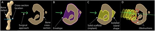
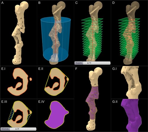
(A) shows the cross-section of a femur that has healed together after an accident in an irregular alignment, with a cavity in the lateral direction. Based on the best possible access for optimal treatment of the bone defect, the surgeon decided to approach the defect from the lateral direction. (B–C) shows the common steps of creating a patient-specific implant to fill the cavity, where the bone geometry is Boolean subtracted from an envelope geometry created to overlap with the defected bone (oftentimes the contralateral bone is used as the envelope), to derive the implant geometry or in the case of an SGBR scaffold, the solid scaffold geometryFootnote1.
(1)
(1) However, as this method does not consider the surgical approach, the scaffold may not be inserted properly due to the obstruction as illustrated in (D). For complicated clinical cases, manually and digitally sculpting a shape that can be inserted without hindrance would incur commercially unrealistic design times. Similarly, if the surgeon has to refine the exterior shape of a scaffold manually with a scalpel during surgery to remove obstructing portions, this may not only prolong the surgery but may also result in significant destruction of the implant, rendering it unfit for implantation.
Figure 1. Obstruction to insertion of a patient-specific implant.
Depending on the defect location, size and shape, the surgical team decides the method of scaffold fixation, such as the scaffold being screwed to the host bone through solid flanges, secured around an intramedullary nail, tied to the host bone using cerclages, or often a combination of these methods. Geometrically merging these solid flange shapes to porous scaffold geometries can be challenging given the current limitations of CAD software. As the surgical strategy is altered, the locations of these flanges would change. Hence, if they were manually created onto a scaffold design, the entire process would have to be repeated.
1.2. Limitations of design software for additive manufacturing
For the one-time manufacturing of patient-specific implants which are manufactured on a per-patient basis, AM is highly attractive compared to conventional methods of manufacturing which are more suited for mass production. The common procedure for 3D printing involves the designed model being imported into AM software (slicing software) as a triangulated surface mesh in Stereolithography (STL) or similar file format, where it is sliced into layers as 3D printing is carried out layer-by-layer. For successful slicing of the model the surface mesh should be free of degenerate or self-intersecting faces, watertight and manifold [Citation18]. These criteria when unsatisfied are commonly known as ‘mesh errors’ which effectively prevents 3D printing. Current CAD software has various limitations and restrictions which renders the design of organic and non-uniform geometry such as patient-specific implants extremely challenging, especially if they are intended to be additively manufactured [Citation19].
Historically, CAD platforms adopted boundary representation (B-rep) for geometric modelling and hence, most of them are still powered by the same [Citation20]. The B-rep modelling represents design models by differentiating its boundary or ‘skin’ which separates model and non-model [Citation21]. Non-uniform rational B-spline (NURBS) modelling and polygonal surface mesh-based modelling, predominantly used by modern CAD platforms are both classed under B-rep modelling. Prior to slicing of a designed model, a NURBS model would be converted into a polygonal surface mesh. Both methods which were adopted and developed prior to the global recognition of 3D printing as a versatile method of manufacturing, have significant shortcomings when used for the design of 3D printable organic shapes.
B-rep modelling requires a large number of polygonal or NURBS faces to represent the boundary of complex geometry, which leads to large file sizes and make simple design processes computationally expensive [Citation22]. Constructive solid geometry (CSG) operations such as Boolean union, difference, and intersection, which are fundamental for creating patient-specific bone scaffolds become computationally expensive [Citation23] and would often fail to produce an error-free mesh [Citation19]. This non-robust nature of CSG operations requires the design engineer to tinker with the surface mesh to achieve error-free meshes, and when that is unlikely, manually manipulate the triangles of the mesh using software tools to ‘repair’ a mesh [Citation19], a step which later became popular within the AM pipeline as ‘mesh repairing’. Perhaps the most unattractive outcome of the above limitations is the inability to automate the creation of complex geometries through a single seamless workflow.
Furthermore, given the different capabilities of geometric modelling software such as Meshmixer (Autodesk, Inc. California, United States), Geomagic (3D Systems, North Carolina, United States), Netfabb (Autodesk, Inc. California, United States), nTopology (nTopology Inc., New York, USA) and MeshLab [Citation24] (open-source), and the lack of a standard protocol, often the design engineer has to transfer models between several software to achieve a single outcome [Citation19]. The result of these restrictions is the highly manual geometric modelling processes the design engineer will need to endure, along with any repetitions of the entire process as surgical strategies are known for their frequent changes.
Within the community of SGBR, many pore architectures are explored, and their properties studied actively. They include the Voronoi tessellation [Citation15, Citation25–30], unit cell based periodic lattice patterns such as simple cubic, body centred cubic, face centred cubic [Citation31–33], and triply periodic minimal surface (TPMS)-based architectures (e.g. Gyroid, Neovius, Schwarz) [Citation34–38] which are complicated geometries which would require many facets to be represented in any B-rep format [Citation22]. The conversion of patient-specific solid scaffold geometries into such complicated porous architectures while ensuring that the output model is 3D printable, is a significant design challenge.
1.3. Novel ‘bottom-up’ SGBR scaffold design workflow
Charbonnier et al. [Citation19] identifies the disadvantages of the traditional ‘top-down’ strategy of combining existing AM and CAD technologies to create a clinically relevant ‘makeshift’ scaffold solution, and then assertively emphasise the need for a ‘bottom-up’ scaffold design strategy where the clinical requirements drive the development of a dedicated AM and CAD technology targeting SGBR. Hence, the need for a novel bottom-up scaffold design workflow that is tailored for the clinical application of SGBR is evident for its successful clinical translation. To the best of authors' knowledge, it is evident through available literature on scaffold design workflows [Citation39–45] that there is no clear consensus within the SGBR community on a standard design procedure for patient-specific SGBR scaffolds that can address the above-mentioned concerns. Furthermore, the technical details of the scaffold design processes expressed in literature is scarce [Citation46]. Although several workflows have been reported for the design of 3D printable anatomical models and patient-specific fixation plates [Citation47], the porous nature of a scaffold significantly complicates the design challenge, and hence make the adoption of these workflows difficult for SGBR. Likewise, some workflows are reported for Craniomaxillofacial reconstructions [Citation48] but given the anatomical differences the adoption of these to other bone defects can be challenging. The FDA-approved Mimics Medical and 3-matic (Materialise NV, Leuven, Belgium) is a commercial software platform that is popular for patient-specific implant design, but many academic and research groups, and small-scale clinical settings find its access economically challenging as well as being too complicated to be used by a surgical team without the comprehensive support of highly specialised design engineers [Citation19, Citation49–51].
The ideal bottom-up workflow envisioned would involve a simple graphical interface which would allow surgeons themselves to input the patient's CT data and the planned surgical strategy, select a few desirable scaffold properties and generate a 3D printable scaffold design, thus eliminating the need for specialised design engineers who would be required to operate complicated software. As the first step towards such a vision, we present here a modular patient-specific 3D printableFootnote2 scaffold design workflow along with its geometric strategies. A prototype of the workflow is implemented in a parametric and generative design platform, namely Rhinoceros 3D and Grasshopper (R&G) software (Robert McNeel & Associates, Washington, USA), within the context of a complex post-traumatic femoral bone defect, followed by its experimental validation by way of AM. The target user of the current workflow is a design engineer who is guided by the instructions of the surgeon. Considering the scarcity of technical details in literature related to scaffold design workflows [Citation46], the said strategies are extensively discussed in Appendix 2 in a generalised software-agnostic manner, in the hope that it will allow an interested reader to replicate the methods, even within a suitable software environment other than R&G.
2. Method: development of the design workflow
A modular design workflow was implemented in R&G to design SGBR scaffolds based on parametric and generative design principles. Rhinoceros 3D is by itself a CAD software best described as a free-form modelling tool. Grasshopper is a companion software developed by the same developers, which enables the creation of parametric and generative design workflows using a graphical programming interface. Generative and parametric design is a design approach based on algorithmic or rule-based design procedure [Citation52] where it creates a strict ‘recipe’ for a design rather than a design itself. As opposed to manual design methods such as free form modelling or sculpting, generative and parametric design grants a non-destructive workflow as well as repeatability and objectivity. R&G, coupled with a few 3rd party Grasshopper plugins offer an excellent suite of tools to manipulate B-reps at their most fundamental level such as vertices, edges, faces, points, lines, surfaces, planes and vectors. Furthermore, R&G has an inherent modular nature which is highly attractive for a workflow that needs to adapt to a multitude of clinical cases and also to different surgical strategies which can frequently change during surgical planning discussions.
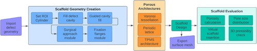
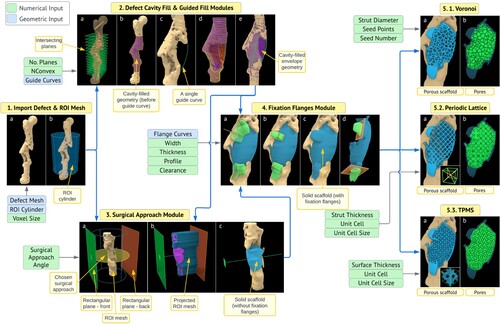
A flowchart of the developed workflow is seen in . The primary input to the workflow is the 3D bone defect model created using image segmentation of patient's CT data and the primary output is the 3D printable surface mesh of the patient-specific scaffold design exported in STL or similar file format, which can be sent to the manufacturer without requiring any post-processing. The first step is to import the created bone defect geometry in the form of a triangular surface mesh. The modules which belong to the section ‘Scaffold Geometry Creation’ in help to create a solid geometry of the scaffold which satisfies all the above-mentioned requirements and is then converted into a porous scaffold geometry using the ‘Porous Architectures’ modules. Finally, the porous scaffold geometry is evaluated for its porosity, pore size distribution, presence of 3D printability inhibiting mesh errors and virtual patient-specific fit using the ‘Scaffold Evaluation’ modules. A real-time demonstration video of the complete workflow can be found in Appendix 1.
Figure 2. Flow chart of the scaffold design workflow.
To overcome the limitations of B-rep modelling with respect to 3D printability, a dedicated plugin for Grasshopper was developed in-house which enabled Functional representation (F-rep) modelling; an alternative technique to B-rep modelling. the F-rep modelling technique, the in-house developed plugin, and the developement of the modules of the workflow are discussed in the next sections, and then are applied to a complex femoral shaft defect.
2.1. Functional representation modelling for additive manufacturable designs
Functional representation (F-rep) is an alternative modelling technique to B-rep modelling [Citation22, Citation53] where a solid object is defined by an implicit function f such that ; for all x where x is any point inside the solid object or on its boundary [Citation54]. The implicit function is also called a ‘level set function’ and it describes the surface level of the solid geometry where
. F-rep results in much smaller file sizes when compared with B-rep files for complex organic and lattice geometries. Boolean operations are straightforward and robust with F-reps and consume much less computational overhead [Citation55, Citation56]. Furthermore, F-rep models can be safely converted into triangular surface meshes that are compatible with current AM pipelines without requiring any mesh repairing or post processing [Citation55, Citation57–59]. Owing to the robust and efficient Boolean operations of implicit modelling and compatibility with AM pipelines, design workflows can be successfully automated. Despite the advantages, most current CAD platforms originally powered by B-rep modelling do not inherently support F-rep modelling [Citation20], including Rhinoceros 3D. A few noteworthy modern platforms are making great strides in migrating implicit geometry into the CAD and AM spaces such as nTopology and Hyperganic (Hyperganic Group, Munich, Germany). However, considering the broader vision of developing a dedicated ‘bottom-up’ scaffold design platform and R&G's ecosystem of plugins, availability of an extensive API (application programming interface), accessibility, R&G enhanced by an in-house developed plugin was chosen as a versatile testbed to prototype the algorithms of the workflow.
OpenVDB is a hierarchical data structure and suite of tools for the efficient representation and manipulation of sparse, time-varying volumetric data discretised on a 3D grid [Citation58]. It is an actively maintained open-sourced code developed in the C++ language. It can represent narrow band level sets (F-reps) efficiently and provides a large set of tools including constructive solid geometry (CSG) operations such as real-time robust Boolean operations as well as offering methods to convert level sets to polygonal surface meshes and vice versa. Therefore, OpenVDB provides a versatile suite of tools that could aid the development of a design workflow for SGBR scaffolds that is robust and semi-automated. OpenVDB is adopted in the 3D animation software Houdini (Side Effects Software Inc, Toronto, Canada) and the open-source software Blender (Blender Foundation).
2.2. Development of the F-rep modelling Grasshopper plugin based on OpenVDB
As R&G does not natively support F-rep modelling, third party plugins are available, some of which are experimental, developed by interested users that enable the processing of F-reps. A notable plugin named Dendro [Citation60], built using OpenVDB, enabled robust Boolean operations within R&G. For the purposes of the workflow presented here, Dendro posed a few limitations. To overcome these, a dedicated Grasshopper plugin was developed in-house that used OpenVDB at its core. Grasshopper plugins are developed in C# language whereas OpenVDB is in C++ language. The P/Invoke method was used to build a C# wrapper API to the relevant OpenVDB functions, following the excellent example created by Fuiger [Citation61]. The architecture of the developed plugin is illustrated in .
Figure 3. Architecture of the in-house developed F-rep modelling Grasshopper plugin.
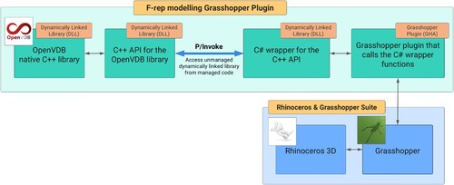
The in-house developed plugin can convert polygonal meshes within R&G into narrow-band level sets and vice versa. During mesh to level set conversion, a unitless parameter named the ‘voxel size’, the size of a single isotropic voxel within the discretised grid, controls the size of the smallest voxel in ‘world units’ and thereby control the resolution of the mesh. World units in the context of R&G is the unit used by the particular coordinate system, which for SGBR scaffold workflows, is usually in millimetres (mm). The smaller the voxel size, the greater the level of details of the mesh captured. The plugin can then utilise the CSG operations within OpenVDB such as Boolean operations, and various smoothing operations of level sets. The output surface meshes are watertight, free of self-intersecting and degenerate faces, manifold and would be composed of quads and triangles. The parameter ‘adaptivity’ controls the degree of adaptive meshing in the output surface mesh. Increasing the adaptivity value would use larger triangles to approximate regions with low local curvature, thus significantly reducing the face count of the final output surface mesh whereas a zero adaptivity value would output an all-quad mesh which are of equal size, but with a large face count. If and when required by file export or other procedures, the conversion of quads of a surface mesh into triangles is a trivial operation well supported by R&G where a single quad is split into two triangles.
Powered by the developed plugin, R&G presents an environment that is highly conducive for the development of a patient-specific SGBR scaffold designing workflow that is modular, parametric, generative and therefore, repeatable, objective, and robust while assuring that its resulting designs are readily 3D printable. Thus, most of its processes are automated except for the ones which govern the design through user-input such as the decisions made by the surgeon.
2.3. Modular scaffold design workflow setup in R&G
Modules and their algorithms were developed to overcome each challenge discussed above which when combined formed an end-to-end seamless SGBR scaffold design workflow that is seen in . Algorithms were developed for the functions of each module, and their code was built by connecting the multitude of code blocks (called Grasshopper components) available via Grasshopper, its 3rd party plugins, and the in-house developed F-rep modelling plugin (). Where the Grasshopper components lacked in functionality, custom C# blocks were written in the ‘C# Script’ component. A collection of components that performed a specific sub-level function in the algorithm were wrapped into Grasshopper clusters, which converts it into a single component with its own inputs and outputs. The setup of the entire workflow on the Grasshopper canvas is shown in (A) which is assembled for the complex femoral shaft defect discussed in the next section.
Figure 4. Hierarchy of modules, clusters, and components on the Grasshopper canvas. (A) Complete workflow. (B) Voronoi module. (C) Exploded view of the ‘Voronoi wireframe’ cluster. (D) Exploded view of the ‘Extract and clean Voronoi line network’ cluster. (E) A region in the cluster showing ground-level Grasshopper components.
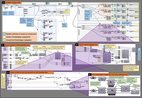
As an exemplar to visualise the hierarchy of modules, clusters and ground-level Grasshopper components and the nature of their connection to one another to perform the functions required by the modules, the ‘Voronoi Scaffold Architecture’ module is shown in (B) and an exploded view of its cluster responsible for creating a Voronoi wireframe is shown in (C). Then, an exploded view of an internal cluster within the Voronoi wireframe cluster that is responsible for extracting a clean network of line segments (wireframe) from 3D Voronoi cells is shown in (D) which shows its Grasshopper components, out of which a selected few are displayed in (E) for clarity. Likewise, the entire workflow is built using a network of Grasshopper components, organised into clusters, whose collective code executes the algorithms of the workflow, ultimately forming a cohesive software inside R&G.
The developed modules and their functions are tabulated in . The underlying geometric strategies of the modules which serves as the secondary contribution of this work are discussed and visualised in Appendix 2, in a software-agnostic manner in the hope that an interested reader is able to replicate similar functionalities on their own, even on suitable software platforms other than R&G such as Houdini (using procedural nodes and networks), Blender (via geometry nodes), nTopology (through recipes) or 3-matic (with scripting).
Table 1. The modules and their functions.
2.4. Evaluation of the design workflow via a clinical case study
The above-described design workflow was applied to a multi-fragmentary fracture of the right femur of a trauma victim after a blast injury where it had healed in a misaligned position, resulting in two pronounced bone defects that compromised biomechanical stability and therefore required surgical reconstruction (Human Ethics Exemption Number 20210001814Footnote3). The surgical team decided that further bone resection was to be avoided and requested bioresorbable patient-specific SGBR scaffolds to fit the complex defect shape. Anonymised CT scan images of the patient's femur were segmented, and a 3D model of the defect was created ().
Figure 5. Femoral bone defect (A) AP view X-ray of the defect (adapted from Laubach et al. [Citation1]) (B) 3D model of the defect following segmentation.
![Figure 5. Femoral bone defect (A) AP view X-ray of the defect (adapted from Laubach et al. [Citation1]) (B) 3D model of the defect following segmentation.](/cms/asset/e26f26d8-96e8-422f-b602-9eb73e816c6b/nvpp_a_2246434_f0005_oc.jpg)
Two solid scaffold geometries were designed for the chosen surgical approach using the workflow setup seen in . The clearance value used for all the models was (Appendix A.2.3). These were then evaluated for patient-specific fit and unobstructive insertion by virtually examining three cross sections.
Next, the two solid scaffold geometries were transformed into two Voronoi tessellations, two periodic lattice architectures (simple cubic – SC and body centred cubic – BCC) and two TPMS architectures (Gyroid and Schwarz P). Following their generation, the evaluation module was used to measure their porosity and their distribution of pore diameters. The output scaffold meshes were checked for 3D printability in terms of mesh errors via the workflow as well as using a commercial 3D printing slicing software named Simplify3D (Simplify3D, Ohio, USA).
Later, prototypes of the defect models and their respective solid and porous scaffold geometries were 3D printed in polylactic acid (PLA) to experimentally validate insertion and fit. The 3D printing was carried out using a Flashforge Dreamer (Zhejiang Flashforge 3D Technology Co., Ltd, Zhejiang Province, China) using a layer height of 0.18 mm, nozzle diameter of 0.4 mm, print speed of 30 mm/s, nozzle temperature of 205C, build temperature of 60
C and with support where necessary for all models.
Finally, the average computation times of individual geometric operations were recorded to evaluate the workflow's computational speed and responsiveness to user-input. The input mesh and ROI mesh statistics were also recorded for comparison. The hardware of the computer used was an Intel Core i7-9700 CPU at 3.00 GHz with 16.0 GB of RAM, with an Intel UHD Graphics 630 integrated graphics adapter and running 64-bit Windows 10.
3. Results: evaluation of the workflow
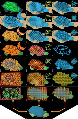
illustrates the workflow being applied to the femoral bone defect along with the respective inputs and outputs of each module. The application of the geometric strategies of each module shown in are discussed in Appendix 2 in context of the femoral defect.
Figure 6. Modules of the workflow applied to the femoral bone defect, with their respective inputs.
The specification of the 12 scaffolds is in with their reported porosities and average effective pore diameters. displays the created 12 porous scaffold surface meshes.
Figure 7. Generated porous scaffold geometries. (A, B) Voronoi tessellation (the inset figure shows the surface mesh). (C) Simple cubic. (D) Body centred cubic. (E) Gyroid. (F) Schwarz P.
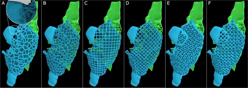
Table 2. Scaffold statistics, porosity and average pore size of the generated scaffolds.
3.1. 3D print feasibility of the output meshes
The output meshes of the generated solid scaffold geometries and the porous scaffold geometries were analysed for 3D print feasibility by checking for 3D printing mesh errors that would hinder the slicing and GCode generation process of 3D printing; specifically, for the presence of non-manifold edges, self-intersecting faces, degenerate triangles, and duplicated faces using both Rhinoceros 3D internal tools and the mesh diagnostic tools offered by Simplify3D. The results are tabulated in along with other mesh statistics such as the number of triangles and edge lengths.
Table 3. Evaluation of the output meshes of the solid and porous scaffold geometries.
All output meshes passed the mesh checks from both diagnostic tools and Simplify3D was able to successfully slice the models and generate its GCode without requiring any post processing. A target minimum edge length tolerance is implemented in the Export Surface Mesh module and as a result, the minimum edge lengths of all meshes are above 0.001 mm or slightly below it (0.0008 mm for SchwarzP_A scaffold). The average edge length depends on the voxel size of the level set grid, which was set to 0.2 during its generation. It can be seen in (A) that the output meshes generated by OpenVDB can be made to be adaptive on demand, that is, the polygons would vary in size depending on the local iso-surface curvature it is trying to approximate, which reduced the number of polygons considerably, thus reducing its file size.
3.2. Patient-specific fit and unobstructive insertion
The solid scaffold geometries (prior to creating the porous architectures) were digitally inspected for their patient-specific fit as well as unobstructive insertion via a visual inspection of three random cross-sections. The femoral bone defect and the insertion of its solid scaffold geometries can be seen in (A). The blue and green line segments represent the surgical approach for the blue and green solid scaffold geometries respectively. Three instances of the insertion process are shown in (A), ending in a perfect patient-specific fit. It is apparent that the two solid geometries can be inserted without any obstruction arising from the complex bone morphology while filling as much of the cavity as possible from the planned surgical approach.
Figure 8. Patient-specific fit and unobstructive insertion of the output scaffold designs were validated by first digitally inserting the solid scaffold geometries into the defect cavity within R&G (A), and subsequently, by 3D printing prototypes in PLA and physically inserting them (B).
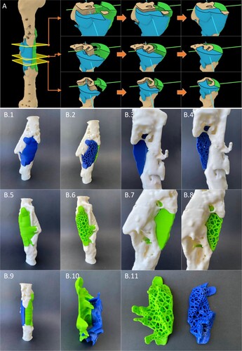
Next all designed models were 3D printed and they can be seen in (B) which shows that all solid and porous scaffold geometries generated using the workflow shows perfect fit and an unobstructive insertion.
(B.10) shows the inside faces of the two solid scaffold geometries, and it can be observed that although the user-set splitting plane (Appendix A.2.2) splits the solid scaffold geometries into two halves (green and blue), by design, regions of one part would still extend itself beyond the splitting plane if the other half could not fill that particular region as per the set surgical approach. This can be clearly observed in (B.10) by the criss-crossing extensions of the two solid scaffold geometries. The module is devised in this way through a series of Boolean operations using the F-rep modelling plugin within the solid scaffold geometry generation process and it ensures that it fills as much void regions as possible as allowed by the user-set surgical approach.
3.3. Average computation times to measure responsiveness to user-input
The workflow was then evaluated for average computation times taken by each major operation to evaluate the time taken by the workflow to respond to a change in user-input (the processing time for each operation). It is important to distinguish that the workflow's ‘computation time’ is not a measure of ‘design time’ for a scaffold design. A design engineer using the workflow would perform many individual geometric operations to arrive at the final design based on their own and the surgeon's judgement. Hence, in addition to the time spent by the computer in processing each operation, design time would include the time spent on assembling the modules as required for each clinical case depending on the number of scaffolds required and the number of regions of interest, and the initial assignment and continuous adjustment of user-input in fine-tuning the design. The computation times of independent operations were measured and reported to gauge the responsiveness of the workflow to user-input, as real-time computations would allow a surgeon to be present either physically or virtually during the design process and provide real-time feedback. For an indicative timeframe, the design process for the femur clinical case was completed in less than an hour, which can be seen in the demonstration video showing the entire workflow in Appendix 1.
Computation times were measured for the femoral bone defect case for three different voxel sizes, 0.2, 0.3 and 0.4, which can be seen in . The voxel size is a key parameter introduced by OpenVDB, which dictates the size of a single voxel belonging to the dynamic voxel data structure which stores the implicit surface [Citation58]. As this value is decreased, greater details of the input mesh are captured at the cost of higher computation times ().
Figure 9. Average computation times (s) for major operations of the workflow calculated for each of the voxel sizes of 0.2, 0.3 and 0.4.
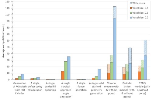
The computation times of all operations increased non-linearly as the voxel size decreased. This is due to the non-linear increase of the face count of the output meshes once a level set is converted to a surface mesh with decreasing voxel sizes. As the face count increases, the number of edges and vertices increase and hence the number of computations which are performed at their level too increases. The ‘Generation of ROI mesh from ROI cylinder’ (Appendix A.1.1) includes the conversion of the surface meshes of the ROI cylinder and the defect mesh into OpenVDB level sets, performing a Boolean intersection between them and converting the result back into a surface mesh. The imported femoral bone defect surface mesh had a triangle count of 375012. The triangle counts of the resultant ROI meshes for each of the voxel sizes 0.4, 0.3 and 0.2 were 453804, 661742 and 1112160, respectively, where smaller voxel sizes would retain greater details of the input defect mesh.
‘A single defect cavity fill operation’ (.2(a-b)) includes the generation of the cavity-fill geometry. The computation times would increase with the number of planes set by the design engineer but for the smallest voxel size which created a highly dense ROI mesh, the computation time is well below 5 s. ‘A single guided fill operation’ (.2(c–d)) includes modifying the convex hull curves using a single user-set curve, which incurred 0.3 s, 0.3 s and 0.4 s for the voxel sizes 0.4, 0.3 and 0.2, respectively. This would allow the design engineer to vary the position of several guide curves simultaneously and see the result in real-time as the computation times are well below 0.5 s. ‘A single surgical approach angle alteration’ (.3(a–c)) involves changing the numerical value of the input angle which recreates the projected ROI mesh, that would be used for the Boolean operation to generate the solid scaffold geometry. As the face count increases with decreasing voxel size, the computation times increased. ‘A single flange alteration’ (.4(a–b)) involves modifying the line segment on which the flange is based, flange width, thickness or any of the other flange inputs, thus recreating the flange geometry. For all voxel sizes, this was below 0.5 s and hence the design engineer can vary the location, shape and orientation of the flange in real-time until they are satisfied before moving to the next step. ‘A single solid scaffold geometry generation’ involves generating the solid scaffold geometries from the defect cavity-fill geometry, the projected ROI mesh, the splitting plane (if there are two surgical approaches) and the flange geometries. A non-linear computation time is observed with a decrease in voxel size. The porous architecture modules, namely, Voronoi, Periodic lattice and TPMS modules (.5) cost a significance computation overhead compared to the other operations for low voxel sizes. The pores are computed after the generation of the porous scaffold geometry, and its computation time can be seen separately in .
Despite the used computer hardware being considered average at the time as it only had 16 GB RAM and lacked a dedicated graphics card, most workflow operations that would require alterations were computed within a few seconds. The operations regarding flanges, guide curves and cavity fills are the ones that require continuous amendments as per surgeons' instructions whereas the surgical approach and the porous scaffold architecture settings are mostly set once. As a result, most of the major operations of the workflow that require further adjustment by the design engineer can be classified as real-time to near-real-time operations.
4. Discussion
Patient-specific SGBR has shown promising regenerative capacity for large bone defects in several clinical case studies [Citation1–3]. However, to date, there is no clear consensus of a scaffold design workflow that addresses practical design challenges during the envisioned routine clinical practice of this interdisciplinary treatment concept [Citation10]. The scaffold shape should match the bone defect and should be designed to facilitate proper surgical insertion into the defect. Furthermore, the output surface mesh of the designed scaffold should pass the criteria that should be satisfied by a surface mesh for it to be technically 3D printable. Moreover, the limitations imposed by B-rep modelling techniques [Citation18, Citation22] of most modern CAD software are not suitable to design organic non-uniform geometry such as patient-specific implants that resemble anatomical shapes. Most of the design revisions which arise as the result of feedback from the surgeons are related to the solid scaffold geometry generation steps. Key decisions by the team of surgeons such as which bone defect voids or cavities of the defect should be filled, their extent of filling, surgical approach, optimal locations for fixation flanges and their shape and size and the way in which a single scaffold should be split into multiple scaffold bodies, affect the solid scaffold geometry. Hence, an optimal workflow should be fast enough to have a surgeon either physically or virtually present to provide real-time feedback while the solid scaffold geometry is generated, as opposed to receiving design feedback after each design revision which would have to be the case if the scaffold geometry computation is slow. The presented SGBR scaffold design workflow setup within R&G and the dedicated in-house developed plugin based on OpenVDB enables the use of a pre-assembled parametric and generative workflow to design patient-specific 3D printable bone scaffolds. A complex femoral bone defect was used as a challenging case study to validate the workflow.
The defect fill module allows the semi-automatic filling of any cavity or void of the bone defect, and use guide curves created between anatomical landmarks to further modify the cavity filled geometry. The only user inputs of this step are the number of intersection planes and the degree of convexity (dictates the degree of fill), the guide curves and the number of vertices it affects which are optional inputs, and the rest is automated by the module. If the design engineer wishes to alter any parameter, the workflow will recreate the lofted cavity fill geometry reflecting the changes in real-time as seen by the computation times in . As intended, the subjectivity of the design engineer is limited to the parameter ‘degree of convexity’ and the ‘number of vertices affected by the guide curves’ which were found to have only a minor effect on the final geometry. Furthermore, this user-input does not compromise the repeatability of the procedure as the input is a numerical value except for the guide curves which are drawn as instructed by the team of surgeons (). Hence, these curves are fixed parameters which would result in minor variations between multiple design engineers. As the computation times of this module are below 0.5 s for all voxel sizes, it can be considered almost real-time enabling real-time surgeon feedback which would drastically reduce design revisions.
The surgical approach module was able to successfully generate scaffold designs which are both patient-specific and unobstructive to its insertion as seen by the digital fit and experimental fit by way of 3D printing (). The design engineer is able to adjust the surgical approach angle with real-time feedback from the surgeon and then generate the solid scaffold geometry within a few seconds. Following this, the design engineer is able to use the fixation flanges module to add fixation flanges at the locations and orientation, with appropriate dimensions as suggested by the surgeon, again with real-time feedback.
The porous architecture modules transform a solid scaffold geometry into a porous one based on the pore architecture chosen by the design engineer. The modules are built to ensure that the porous geometry is geometrically confined to the solid scaffold geometry. Once the solid scaffold geometry is finalised, the surgeon need only provide the type of pore architecture, porosity and average pore diameter required and the surgeon no longer needs to provide feedback. Subsequently the design engineer discusses with the designated additive manufacturer for a feasible strut diameter or surface thickness for the porous scaffold design, which largely depends on the printing material and the 3D printer. Then the design engineer is able to use the porous architecture modules accordingly and produce an adaptive surface mesh that is free from 3D printing mesh errors, is patient-specific and can be inserted without any obstructions. The numerical inputs and the guide curves and flange curves can be saved as R&G files which would preserve the entire tree of parameters that are necessary to replicate the exact scaffold design, thus making future changes to the design possible. Given the robustness of the Boolean operations of F-rep modelling [Citation55, Citation56], the developed workflow is semi-automated with minimal design input except for the input required by the surgical strategy. An interesting alternative to the TPMS porous architectures module is the open-source tool ‘A Simple Lattice Infiller’ (ASLI), an F-rep based functionally graded lattice generator which can convert a solid geometry into a TPMS based porous geometry [Citation62].
The workflow is built to accept the voxel size as a numerical input in the very beginning of the workflow (), alongside the file import of the defect mesh. This is done with the intention that the design engineer is to use a larger voxel size in the beginning, which grants design speed via reduced computation times to establish the workflow modules and their input parameters while continuous adjustments are necessary as per the real-time feedback provided by the surgeons, and then once the solid scaffold geometry is generated, have the workflow automatically recompute with a smaller voxel size to achieve greater resolution. This approach grants real-time computation times to adjust and fine-tune the input parameters to satisfy the requirements of the surgeons, after which the workflow can recompute on its own the scaffold geometries with higher resolutions prior to validation by the team of surgeons and then being sent off to the manufacturer. The final value should be chosen by the design engineer considering the face count and edge lengths of the input surface mesh of the defect and the resolution of the 3D printer used by the designated manufacturer. The level of detail however is limited by the level of details present in the patient's CT scan and resulting input 3D mesh. It was found for the femoral bone defect, a voxel size of 0.2 was sufficient to capture all the fine details of the input defect mesh which can be effectively 3D printed using a material extrusion-based 3D printer. Moreover, the generation of adaptive meshes ensure optimised and smaller file sizes which can be sent off to the manufacturer.
In summary, we have developed a robust design workflow that allows interdisciplinary teams to create complex porous geometries of 3D printable scaffolds in a very short time (<1 hour for the femur case), which demonstrates the value of this design workflow not only for surgeons and design engineers, but also for additive manufacturers, in the sense of large-scale, routine application.
There are a few limitations to this study. Although the ideally envisioned user of a SGBR design workflow is the surgeon, the current prototype stage of the workflow is missing a graphical user interface (GUI) and still relies on the user having CAD knowledge. Hence, the target user of the workflow is a design engineer who is guided by the instructions of the surgeon. Thus, the workflow is still at a stage where the user is required have general proficiency in CAD platforms to be able to effectively use it; specifically, one who has learnt the basics of R&G. Furthermore, the workflow must be further validated with a number of additional complex bone defects before a definitive conclusion can be made regarding its accuracy.
5. Conclusion and outlook
The overarching vision of this work is to develop a dedicated SGBR scaffold design software that can be used by the team of clinicians/surgeons with minimal user-input, without the need of specialised engineers to handle complicated software. The work described in this manuscript is an essential steppingstone towards achieving this larger vision, which in its current stage is in the form of a software prototype developed within R&G. The modular workflow proposed for the design of SGBR scaffolds which is a timely requirement for the treatment of complex bone defects has proven successful, as solid and porous scaffold geometries were created that are patient-specific, can be 3D printed without additional pre-processing, and can be inserted through the planned surgical approach without obstructions. Prototype implementation of the workflow was demonstrated on the R&G platform coupled with an inhouse-developed plugin based on the open-source OpenVDB library which granted F-rep modelling capabilities. The workflow is able to run on a general-purpose computer with all of the operations that require real-time adjustments being computed within a few seconds. This would allow the design engineer to work together with the surgeon and generate a patient-specific scaffold design that is ready to be sent out to the 3D printing manufacturer.
In the future, the developed workflow is to be validated with additional clinical cases. Furthermore, a standalone GUI is expected to be developed in a manner that allows a surgeon who has minimal experience with CAD platforms to be able to use it effectively and generate patient-specific scaffold designs. Moreover, as DICOM data is stored and later segmented within a voxel space, the direct translation of the segmented voxels into OpenVDB compliant VDB files would preserve all details of the CT images of the defect model as opposed to converting it to a surface mesh and converting it back to a level set stored in a voxel data structure. Lastly, finite element analysis is to be implemented to evaluate the structural response of scaffold designs which allows the optimisation of them prior to fabrication.
Acknowledgements
The authors would like to acknowledge Prof. Frank Hildebrand and Dr. Heide Delbrück (Department of Orthopaedics, Trauma and Reconstructive Surgery, RWTH Aachen University Hospital, Germany) for their collaboration and provision of the CT data relevant to the femoral bone defect.
6. Disclosure statement
Dietmar W. Hutmacher is a cofounder and shareholder of Osteopore International Pty Ltd., a company specialised in 3D printed bioresorbable implants to assist with bone healing. The remaining authors declare that the research was conducted in the absence of any commercial or financial relationships that could be construed as potential conflicts of interest.
Data availability
The data cannot be shared at this time due to legal or ethical reasons.
Correction Statement
This article has been corrected with minor changes. These changes do not impact the academic content of the article.
Additional information
Funding
Notes
1 The term ‘solid scaffold geometry’ is used here to refer to the shape of the scaffold prior to being made porous, after which it will be referred to as ‘porous scaffold geometry’. See for illustrations of these.
2 3D printable: within the context of this study refers to a surface mesh being free from 3D printing mesh errors.
3 The QUT University Human Research Ethics Committee assessed this research as meeting the conditions for exemption from HREC review and approval in accordance with Section 5.1.22 of the National Statement on Ethical Conduct in Human Research (2007)
References
- Laubach M, Suresh S, Herath B, et al. Clinical translation of a patient-specific scaffold-guided bone regeneration concept in four cases with large long bone defects. J Orthop Translat. 2022 May;34:73–84. doi: 10.1016/j.jot.2022.04.004.
- Kobbe P, Laubach M, Hutmacher DW, et al. Convergence of scaffold-guided bone regeneration and RIA bone grafting for the treatment of a critical-sized bone defect of the femoral shaft. Eur J Med Res. 2020 Dec;25(1):70. doi: 10.1186/s40001-020-00471-w.
- Castrisos G, Gonzalez Matheus I, Sparks D, et al. Regenerative matching axial vascularisation of absorbable 3d-printed scaffold for large bone defects: a first in human series. J Plastic, Reconstructive Aesthetic Surgery: JPRAS. 2022 Jul;75(7):2108–2118. doi: 10.1016/j.bjps.2022.02.057.
- Schemitsch EH. Size matters: defining critical in bone defect size! J Orthop Trauma. 2017 Oct;315:S20–S22. doi: 10.1097/BOT.0000000000000978.
- Dahl MT, Morrison S. Segmental bone defects and the history of bone transport. J Orthop Trauma. 2021 Oct;35(Suppl4):S1–S7. doi: 10.1097/BOT.0000000000002124.
- Kern T. Managing bone defects in the femur with a motorized intramedullary bone transport nail: case review with follow-up. J Orthop Trauma. 2021 Oct;35(Suppl4):S8–S12. doi: 10.1097/BOT.0000000000002120.
- Hutmacher DW. Scaffolds in tissue engineering bone and cartilage. Biomaterials. 2000 Dec;21(24):2529–2543. doi: 10.1016/S0142-9612(00)00121-6.
- Cheng A, Schwartz Z, Kahn A, et al. Advances in porous scaffold design for bone and cartilage tissue engineering and regeneration. Tissue Eng Part B, Rev. 2019 Feb;25(1):14–29. doi: 10.1089/ten.teb.2018.0119.
- Feng P, Zhao R, Tang W, et al. Structural and functional adaptive artificial bone: materials, fabrications, and properties. Adv Funct Mater. 2023 Jun;33(23):2214726. doi: 10.1002/adfm.v33.23.
- Laubach M, Hildebrand F, Suresh S, et al. The concept of scaffold-guided bone regeneration for the treatment of long bone defects: current clinical application and future perspective. J Funct Biomater. 2023 Jun;14(7):341. doi: 10.3390/jfb14070341.
- Lan W, Huang X, Huang D, et al. Progress in 3D printing for bone tissue engineering: a review. J Mater Sci. 2022 Jul;57(27):12685–12709. doi: 10.1007/s10853-022-07361-y.
- Zhang XY, Fang G, Zhou J. Additively manufactured scaffolds for bone tissue engineering and the prediction of their mechanical behavior: a review. Materials. 2017 Jan;10(1):50. doi: 10.3390/ma10010050.
- Zhang L, Yang G, Johnson BN, et al. Three-dimensional (3d) printed scaffold and material selection for bone repair. Acta Biomater. 2019 Jan;84:16–33. doi: 10.1016/j.actbio.2018.11.039.
- Germaini MM, Belhabib S, Guessasma S, et al. Additive manufacturing of biomaterials for bone tissue engineering – a critical review of the state of the art and new concepts. Prog Mater Sci. 2022 Oct;130:100963. doi: 10.1016/j.pmatsci.2022.100963.
- Herath B, Suresh S, Downing D, et al. Mechanical and geometrical study of 3D printed voronoi scaffold design for large bone defects. Mater Des. 2021 Dec;212:110224. doi: 10.1016/j.matdes.2021.110224.
- Wang F, Tankus EB, Santarella F, et al. Fabrication and characterization of PCL/HA filament as a 3D printing material using thermal extrusion technology for bone tissue engineering. Polymers. 2022 Feb;14(4):669. doi: 10.3390/polym14040669.
- Korn P, Jehn P, Nejati-Rad N, et al. Pitfalls of surgeon-engineer communication and the effect of in-house engineer training during digital planning of patient-specific implants for orbital reconstruction. J Oral Maxillofacial Surgery: Official Journal of the American Association of Oral and Maxillofacial Surgeons. 2022 Apr;80(4):676–681. doi: 10.1016/j.joms.2021.12.003.
- Minetto R, Volpato N, Stolfi J, et al. An optimal algorithm for 3D triangle mesh slicing. Comput Aided Des Appl. 2017 Nov;92:1–10. doi: 10.1016/j.cad.2017.07.001.
- Charbonnier B, Hadida M, Marchat D. Additive manufacturing pertaining to bone: hopes, reality and future challenges for clinical applications. Acta Biomater. 2021 Feb;121:1–28. doi: 10.1016/j.actbio.2020.11.039.
- Vilbrandt T, Pasko A, Vilbrandt C. Fabricating nature. Technoetic Arts. 2009;7(2):165–173. doi: 10.1386/tear.7.2.165/1.
- Stroud I. Boundary representation modelling techniques. London: Springer; 2006. doi: 10.1007/978-1-84628-616-2.
- Kambampati S, Jauregui C, Museth K, et al. Geometry design using function representation on a sparse hierarchical data structure. Comput Aided Des Appl. 2021 Apr;133:102989. doi: 10.1016/j.cad.2020.102989.
- Fryazinov O, Vilbrandt T, Pasko A. Multi-scale space-variant FRep cellular structures. Comput Aided Des Appl. 2013 Jan;45(1):26–34. doi: 10.1016/j.cad.2011.09.007.
- Cignoni P, Callieri M, Corsini M, et al. MeshLab: an open-source mesh processing tool. 2008.
- Sharma N, Ostas D, Rotar H, et al. Design and additive manufacturing of a biomimetic customized cranial implant based on voronoi diagram. Front Physiol. 2021 Apr;12:647923. doi: 10.3389/fphys.2021.647923.
- Chen H, Liu Y, Wang C, et al. Design and properties of biomimetic irregular scaffolds for bone tissue engineering. Comput Biol Med. 2021 Mar;130:104241. doi: 10.1016/j.compbiomed.2021.104241.
- Klatt MA, Lovrić J, Chen D, et al. Universal hidden order in amorphous cellular geometries. Nat Commun. 2019 Feb;10(1):811. doi: 10.1038/s41467-019-08360-5.
- Deering J, Dowling KI, DiCecco LA, et al. Selective voronoi tessellation as a method to design anisotropic and biomimetic implants. J Mech Behav Biomed Mater. 2021 Apr;116:104361. doi: 10.1016/j.jmbbm.2021.104361.
- Chen W, Dai N, Wang J, et al. Personalized design of functional gradient bone tissue engineering scaffold. J Biomech Eng. 2019 Apr;141:111004. doi: 10.1115/1.4043559.
- Du Y, Liang H, Xie D, et al. Design and statistical analysis of irregular porous scaffolds for orthopedic reconstruction based on voronoi tessellation and fabricated via selective laser melting (SLM). Mater Chem Phys. 2020 Jan;239:121968. doi: 10.1016/j.matchemphys.2019.121968.
- Chen H, Han Q, Wang C, et al. Porous scaffold design for additive manufacturing in orthopedics: A review. Front Bioeng Biotechnol. 2020 Jun;8:609. doi: 10.3389/fbioe.2020.00609.
- Gatto ML, Furlani M, Giuliani A, et al. Biomechanical performances of PCL/HA micro- and macro-porous lattice scaffolds fabricated via laser powder bed fusion for bone tissue engineering. Mater Sci Eng C, Materials Biol Appl. 2021 Sep;128:112300. doi: 10.1016/j.msec.2021.112300.
- Onal E, Frith JE, Jurg M, et al. Mechanical properties and in vitro behavior of additively manufactured and functionally graded Ti6Al4V porous scaffolds. Metals. 2018 Mar;8(4):200. doi: 10.3390/met8040200.
- Karakoç A. RegionTPMS – region based triply periodic minimal surfaces (TPMS) for 3-D printed multiphase bone scaffolds with exact porosity values. SoftwareX. 2021 Dec;16:100835. doi: 10.1016/j.softx.2021.100835.
- Shi J, Zhu L, Li L, et al. A TPMS-based method for modeling porous scaffolds for bionic bone tissue engineering. Sci Rep. 2018 May;8(1):7395. doi: 10.1038/s41598-018-25750-9.
- Günther F, Wagner M, Pilz S, et al. Design procedure for triply periodic minimal surface based biomimetic scaffolds. J Mech Behav Biomed Mater. 2022 Feb;126:104871. doi: 10.1016/j.jmbbm.2021.104871.
- Poltue T, Karuna C, Khrueaduangkham S, et al. Design exploration of 3d-printed triply periodic minimal surface scaffolds for bone implants. Int J Mech Sci. 2021 Dec;211:106762. doi: 10.1016/j.ijmecsci.2021.106762.
- Verma R, Kumar J, Singh NK, et al. Design and analysis of biomedical scaffolds using TPMS-Based porous structures inspired from additive manufacturing. Coatings World. 2022 Jun;12(6):839. doi: 10.3390/coatings12060839.
- Milovanovic JR, Stojkovic MS, Husain KN, et al. Holistic approach in designing the personalized bone scaffold: the case of reconstruction of large missing piece of mandible caused by congenital anatomic anomaly. J Healthc Eng. 2020 Nov;2020:6689961. doi: 10.1155/2020/6689961.
- Han HH, Shim JH, Lee H, et al. Reconstruction of complex maxillary defects using patient-specific 3d-printed biodegradable scaffolds. Plastic Reconstructive Surgery Global Open. 2018 Nov;6(11):e1975. doi: 10.1097/GOX.0000000000001975.
- Park H, Choi JW, Jeong WS. Clinical application of three-dimensional printing of polycaprolactone/beta-tricalcium phosphate implants for cranial reconstruction. J Craniofac Surg. 2022 Mar;33(5):1394–1399. doi: 10.1097/SCS.0000000000008595.
- Bahraminasab M. Challenges on optimization of 3d-printed bone scaffolds. Biomed Eng Online. 2020 Sep;19(1):69. doi: 10.1186/s12938-020-00810-2.
- Memon AR, Wang E, Hu J, et al. A review on computer-aided design and manufacturing of patient-specific maxillofacial implants. Expert Rev Med Devices. 2020 Apr;17(4):345–356. doi: 10.1080/17434440.2020.1736040.
- Koc B, Acar AA, Weightman A, et al. Biomanufacturing of customized modular scaffolds for critical bone defects. CIRP Ann. 2019 Jan;68(1):209–212. doi: 10.1016/j.cirp.2019.04.106.
- Modi YK, Sanadhya S. Design and additive manufacturing of patient-specific cranial and pelvic bone implants from computed tomography data. J Brazilian Soc Mech Sci Eng. 2018 Oct;40(10):503. doi: 10.1007/s40430-018-1425-9.
- Burton HE, Peel S, Eggbeer D. Reporting fidelity in the literature for computer aided design and additive manufacture of implants and guides. Addit Manuf. 2018 Oct;23:362–373.
- Chen X. Parametric design of patient-specific fixation plates for distal femur fractures. Proc Inst Mech Eng Part H, J Eng Med. 2018 Sep;232(9):901–911. doi: 10.1177/0954411918793668.
- Oh JH. Recent advances in the reconstruction of cranio-maxillofacial defects using computer-aided design/computer-aided manufacturing. Maxillofac Plast Reconstr Surg. 2018 Dec;40(1):2. doi: 10.1186/s40902-018-0141-9.
- Shrivastava A, Jain NK, Salhotra R. Modeling of custom patient-specific implants of different knee joints components considering different materials. In: Advancement in materials processing technology. Springer Singapore; 2022. p. 229–238. doi: 10.1007/978-981-16-3297-6_23.
- Chae MP, Chung RD, Smith JA, et al. The accuracy of clinical 3D printing in reconstructive surgery: literature review and in vivo validation study. Gland Surg. 2021 Jul;10(7):2293–2303. doi: 10.21037/gs.
- Valding B, Zrounba H, Martinerie S, et al. Should you buy a three-dimensional printer? A study of an orbital fracture. J Craniofac Surg. 2018 Oct;29(7):1925–1927. doi: 10.1097/SCS.0000000000005048.
- Caetano I, Santos L, Leitão A. Computational design in architecture: defining parametric, generative, and algorithmic design. Front Archit Res. 2020 Jun;9(2):287–300. doi: 10.1016/j.foar.2019.12.008.
- Ghadai S, Jignasu A, Krishnamurthy A. Direct 3D printing of multi-level voxel models. Additive Manuf. 2021 Apr;40:101929. doi: 10.1016/j.addma.2021.101929.
- Pasko A, Adzhiev V, Sourin A, et al. Function representation in geometric modeling: concepts, implementation and applications. Vis Comput. 1995 Aug;11(8):429–446. doi: 10.1007/BF02464333.
- Yngve G, Turk G. Robust creation of implicit surfaces from polygonal meshes. IEEE Trans Vis Comput Graph. 2002 Oct;8(4):346–359. doi: 10.1109/TVCG.2002.1044520.
- Duan Z, Yang Q, Meng X, et al. Detailed voxel-based implicit modeling with local boolean composition of discrete level sets. IEEE Access. 2020;8:48376–48385. doi: 10.1109/Access.6287639.
- Azernikov S, Fischer A. Anisotropic meshing of implicit surfaces. In: International Conference on Shape Modeling and Applications 2005 (SMI' 05). 2005 Jun. 94–103. Cambridge, MA, USA: IEEE. doi: 10.1109/SMI.2005.5.
- Museth K. VDB: high-resolution sparse volumes with dynamic topology. ACM Trans Graph. 2013;32(3):1–22. doi: 10.1145/2487228.2487235.
- Schaefer S, Warren J. Dual marching cubes: primal contouring of dual grids. In: Proceedings 12th Pacific Conference on Computer Graphics and Applications, 2004. PG 2004. 2004 Oct. 70–76. Seoul, Korea (South): IEEE. doi: 10.1109/PCCGA.2004.1348336.
- Oenning R. Ryein/Dendro: Volumetric modeling for grasshopper built on top of openvdb [Internet]. [cited 2023 Jul 2]. Available from: https://github.com/ecrlabs/dendro
- Fugier D. Dalefugier/Moose: Demonstrates how to share a common library with both a C++ and a C# plug-in. [Internet]. [cited 2023 Jul 2]. Available from: https://github.com/dalefugier/Moose
- Perez-Boerema F, Barzegari M, Geris L. A flexible and easy-to-use open-source tool for designing functionally graded 3D porous structures. Virtual Phys Prototyp. 2022 Jul;17(3):682–699. doi: 10.1080/17452759.2022.2048956.
Appendices
Appendix 1.
Demonstration video of the complete workflow
A demonstration video of the complete workflow is at https://doi.org/10.6084/m9.figshare.22656337. The playback speed has not been increased and is in real-time.
Appendix 2.
Modules of the workflow and their geometric strategies
The geometric strategies of the modules are explained here with reference to the complex femoral shaft defect discussed in the study. The defect cavity can be seen below in (A).
Figure A1. Steps of the defect cavity fill module.
A.1. Import defect
A.1.1. Defect mesh import and region of interest (ROI) isolation module
Once the defect mesh is imported, as the first step, the design engineer needs to create a standard cylinder within Rhinoceros 3D and position it over the region of interest (ROI) as shown in (B), which would be named ‘ROI cylinder’. The requirement of the cylinder is to envelope the region of interest and hence the exact position and size is not important. The module would then isolate the region of the defect mesh which falls within the cylinder through the below Boolean intersection operation. The result is termed ‘ROI defect mesh’.
(A1)
(A1) Isolating a smaller ROI encapsulating the defect in a large bone model, especially in a model such as a humerus where the defect is limited to a smaller region, helps to reduce the computational overhead.
A.2. Solid scaffold geometry creation
A.2.1. Defect cavity fill and guided fill modules
The next steps of the defect cavity filling process is shown in (B–F). The 2 flat surfaces of the cylinder would be extracted by the module, and it will create a user set number of planes (‘NLayers’ in (C); planes are green coloured) through the longitudinal axis (red) of the cylinder with their normal aligned to the same. The ROI defect mesh will be intersected by these planes to obtain the intersect curves (orange) in (D). The next steps are illustrated for a single cross-sectional plane as seen in (E) for more clarity. Depending on the complexity of the defect, a single plane may have multiple closed curves ((E.I)).
These intersect curves are then exploded into their line segments and vertices by the module, after which their 2D convex hull (the shortest convex curve that will enclose all of the vertices), will be calculated (yellow) as seen in (E.II). Then the convex hull curve is geometrically pulled towards the ROI defect mesh based on both, the distance of its vertices to the ROI defect mesh, and the user-input parameter ‘NConvex’ ((E.III)). This latter parameter governs the degree of convexity of the cavity fill and basically controls how close fitting the cavity fill should be. The final cavity filled curve is shown in (E.IV) (yellow). Lastly, the module will loft a surface mesh through all the yellow cavity filled curves of each plane to obtain the ‘cavity fill geometry’ (purple in (F)). (G) shows the cavity that was just filled and the lofted cavity fill geometry respectively.
On occasion, the surgeon might require certain void regions outside the cavity to be covered by the scaffold. The workflow supports filling the regions outside the cavity through user-input curves that will be termed ‘guide curves’ which are provided by the surgical team. The procedure is illustrated in .
Figure A2. Steps in the guided cavity fill module.
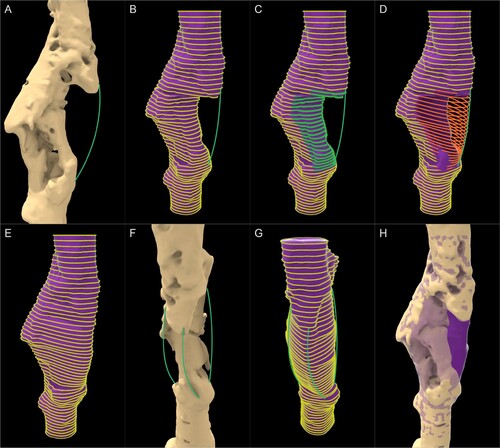
The surgical team requested that the void in the anterior-lateral direction (seen under the green curve in (A)) be covered by the scaffold to enhance the structural stability of the femur. Hence the scaffold geometry was required to be extended up to the green curve. The module can assign such curves drawn within Rhinoceros 3D as user-inputs and extend the lofted cavity-fill geometry. The loft curves of each plane are exploded to their vertices and is pulled towards the guide curve automatically ((C-D)) and a new lofted mesh is constructed using the new curves as seen in (E). Two more curves are drawn as instructed by the surgeon to increase structural stability ((F)) and the lofted mesh is recreated by the module automatically ((G)). (H) shows the lofted geometry (in purple with reduced opacity) guided by the green curves overlaid on the malformed femur. This purple geometry, once Boolean differenced with the bone defect, would ideally be the region to be filled with regenerated bone, and hence would be the shape of the solid scaffold geometry which would later be made porous.
A.2.2. Surgical approach module
The ‘Surgical approach’ module is to overcome the challenge seen in where the scaffold geometry should have no obstructions to its insertion by existing bone. The module will take a numerical input which can range from 0 to 360
for the surgical approach. The mechanism of the ‘Surgical Approach’ module is illustrated in . The roman numerals I and II in the figure labels show the cross-sectional and 3 dimensional views for each step respectively.
Figure A3. Steps of the Surgical approach module. (I) 2D view and (II) 3D view. (B.II) rays originating from only a single vertical set of vertices are shown for clarity.
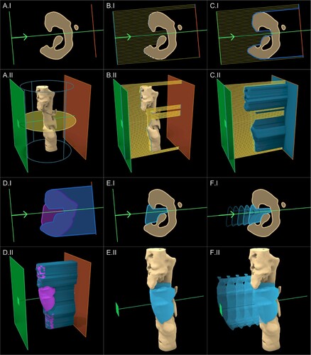
The surgical approach is setup around the longitudinal axis of the ROI cylinder, which is shown by the blue outline, and revolves on the plane shown by the yellow circle in (A) based on the numerical angle input which can range from 0 to 360
. Internally, the module will implement 2 planar rectangular surfaces in front (towards the surgical approach) and back (against the surgical approach) of the ROI defect mesh depicted by the green and orange planes respectively in (B). The 2 planes are subdivided into 2 rectangular grids based on a pre-set resolution which is automatically chosen by the module. Subsequently, rays originating from the vertices of the front plane (green) are projected onto the respective vertices on the back plane (orange) as seen in (B) (in the 3D view in (B.II), rays originating from only a single vertical set of vertices are shown for clarity). The points where the rays are intersected by the ROI defect mesh are indicated in dark blue in (C). The module will connect each such intersection point and create surface mesh which would be termed ‘projected ROI mesh’ as seen in (C) in blue. An apt analogy to grasp this procedure is the surface created by draping a silky fabric on top of the ROI defect mesh.
To generate the scaffold geometry in , as per Equation 1 the lofted geometry (purple) was Boolean subtracted from the defect geometry (beige), which resulted with its obstructions. To overcome this, instead of the defect geometry (beige), the projected ROI mesh (blue) seen in (C) would be used for the Boolean operation.
(A2)
(A2) (D) shows the 2 geometries used for the Boolean operation followed by (E) which shows its result which is in light blue. (F) shows this newly created solid scaffold geometry being inserted into the defect cavity without any hindrance.
It can be seen in (E.II) that the region of the solid scaffold geometry that would have been an obvious obstruction from the top protruding bony ridge located towards the anterior-lateral side of the femur, is effectively removed from this procedure from the top of the solid scaffold geometry. In the 2D cross-sectional views ((E.I)), the removal of obstructions is clear. The underfilling created by this process cannot be avoided as any more filling would create obstructions to the insertion of the scaffold. However, the nature of the procedure further ensures that the underfilling areas are sealed off by the scaffold, allowing them to be filled with bone graft. Moreover, the procedure also removes the isolated islands created in (C) automatically. As the numerical value of the user input angle is varied, the resulting projected ROI mesh and the resulting solid scaffold geometry would regenerate accordingly.
If the surgeon wishes to use multiple surgical approaches (for multiple scaffold bodies), this module can be duplicated. It is assumed that a single scaffold would be inserted from each of these surgical directions and hence, a ‘Split Plane’ helper module automatically takes in 2 surgical directions and create a splitting plane to split the collective solid scaffold geometry into 2 solid geometries that can be inserted from the respective surgical approaches. A set of numerical user inputs are setup to control the orientation of the splitting plane if required. If only a single surgical approach is used with a single scaffold body, this latter module can simply be ignored.
A.2.3. Fixation flanges module
In clinical practice, bone scaffolds are securely attached to the host bone using numerous methods such as being screwed to the host bone, press-fitted into the cavity and securing with suture or cerclages applied circumferentially to the bone and/or in situ fixation such as nail or plate, or a combination of these methods. Currently, the workflow supports the semi-automatic generation of fixation flanges which would be left solid during the transformation of the solid scaffold geometry into its porous geometry. These fixation flanges would be used to screw the scaffold onto the host bone to prevent internal dislodgement. Observing the anatomical location of the defect, its size, the direction of surgical access and the size of the incision, the surgeon would decide the optimum fixation locations for each scaffold. The stages of the module can be seen in .
Figure A4. Steps of the Fixation Flanges module along with their respective numerical inputs.
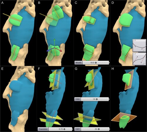
Once the surgeon decides on the locations for the flanges, the design engineer has to create a line segment for each flange within Rhinoceros 3D, and loosely position them over the scaffold as seen in (A). Two flanges are created for this scaffold geometry and hence two lines are drawn which are depicted in yellow. Once these lines are referenced as user inputs for the module, internally it will be projected onto the mesh (red lines) along the normal of the surface mesh face closest to it, around which a flange would be generated automatically by the module on top of the surface of the scaffold and bone meshes.
As seen in (B), when the line is manipulated, the flange would reposition itself automatically. The width of the flange can be altered by numerical user input as shown in (C). Similarly, the thickness can be varied. Furthermore, the profiles of the flanges mimic the Bezier graphs connected to the module as user input, which can be seen in (D), which allows the design engineer to obtain any shape desirable by the surgeon while assuring that the workflow is parametric and repeatable. Once, the design engineer is satisfied with the location, size and shape of the flanges as per the instructions of the surgeon, it is seamlessly integrated into the scaffold geometry using a Boolean union operation which is powered by the F-rep modelling plugin, whose result is shown in (E).
However, prior to making the scaffold geometry porous, the regions of the flanges which should be solid must be demarcated. This is done by the ‘Flange Split’ helper module, where it will position a rectangular plane through the projected red line around which the flange is generated. Several numerical user inputs allow the planar surface to travel along the projected red line ((F)), rotate the surface around the X-axis and Y-axis ((G)) and scale the rectangular surface to completely demarcate the solid regions of the flanges. The isolated flanges are illustrated in green and their intersection lines with the rectangular planes are shown in yellow in (H). Once the flanges are isolated, the blue scaffold geometry is ready to be converted into its porous scaffold geometry.
Another numerical input is introduced at this stage known as the ‘Clearance’ which is a numerical value that produces a negative (shrinks) or positive (dilates) offset to the level set of the solid scaffold geometry. This is used to rectify any 3D printing offsets created in the manufacturing stage as certain 3D printers and print settings could produce slightly larger or smaller prints. The value can be found by test printing a primitive shape (a cube) and measuring the dimensional difference between the as-fabricated and as-designed models.
A.3. Porous architectures
The key feature of any SGBR scaffold is its porous nature and is characterised by its porous architecture, porosity and pore size distribution. The workflow has modules to transform the solid scaffold geometry into the below porous architectures. illustrates the steps of each module.
Voronoi tessellation
Periodic lattice architectures
Triply periodic minimal surface structures
Figure A5. Steps of the Scaffold Architectures modules (top: Voronoi, middle: periodic lattices, bottom: triply periodic minimal surfaces).
A.3.1. Voronoi tessellation
The Voronoi tessellation has gained popularity within the bone tissue engineering community owing to its close resemblance to trabecular bone, its seemingly interesting mathematical properties, the controllability of its randomness, and its ability to be optimised to produce a wide spectrum of mechanical properties. The ‘Voronoi Module’ allows any geometry to be converted into a Voronoi porous scaffold whose steps are illustrated in ( A–B).
The primary inputs to this module are the scaffold geometry, the rectangular surfaces which were generated to demarcate the solid flanges and 2 user-set numerical values ‘Strut Diameter’ and ‘Number of Seed Points’. The strut diameter is the diameter of the struts of the porous scaffold. This module would shrink (negative offset) the scaffold geometry surface by strut diameter to conform the struts which are generated on top of the surface to be within the confines of the scaffold geometry. Furthermore, it will split the flanges into their own geometries which can be later integrated with the porous geometry through a Boolean union operation. Finally, it will isolate the intersection curves of the flanges with the rectangular splitting surface to later merge it to the lattice.
The solid scaffold geometry which was subjected to a negative offset is seen in blue in (A). The solid flanges can be seen in green, and the flange intersection curves can be seen in yellow. In (B.I) the bounding box of the scaffold geometry is calculated and can be seen in red, which is then randomly populated with seed points (yellow). The workflow allows the use of a density-based selection of vertices of the surface mesh of the solid scaffold geometry as seed points which can be controlled by a user-inputs ‘number of vertices’ of the mesh to be used as additional seed points (green). Using mesh vertices as seed points allows the Voronoi tessellation to better represent thinner regions such as the edges of the solid scaffold geometry. This would create smaller Voronoi cells near regions with a high density of seed points which can be seen in (B.I) and (B.III).
Once the seed points are populated, internally the module will create the Voronoi structure and will output the cells and its edges as displayed in 8(B.II). Subsequently, the Voronoi cells which intersect the scaffold geometry mesh are filtered to reduce calculation time as seen in (B.III). Then the network of lines is cleaned to remove duplicate lines, remove line segments shorter than a pre-set tolerance, and merge vertices within a pre-set tolerance. Finally, a clean topographical network of lines or a wireframe of the Voronoi scaffold is generated as seen in (B.IV). However, upon close inspection (inset figure in (B.IV)), it can be noticed near the thinner regions of the scaffold geometry that the seed points chosen from the mesh vertices have resulted in a jagged wireframe. To overcome these jagged edges, these vertices were isolated and grouped based on a ‘density-based spatial clustering of applications with noise’ (DBSCAN) algorithm and each group were connected by a single line to form a ridge between the jagged points. These lines are indicated in red in (B.V). This step would result in a complete wireframe around which a level-set can be created to form a 3D geometry.
Using the F-rep modelling plugin, the wireframe is converted into 3D struts by creating a narrow band level-set around the lines with a fixed diameter equal to the ‘Strut Diameter’. This is merged to the solid flanges through a Boolean union operation, which results in a complete 3D printable porous scaffold geometry as seen in (B.VI).
A.3.2. Periodic lattice structures
Similar to the Voronoi module, the ‘Periodic Lattice’ module is capable of creating a wide array of periodic lattice structures. The module whose steps are displayed in (A–C) houses a library of unit cells seen in literature such as body centred cubic, face centred cubic, prime cubic, tetrahedral, etc…Based on the dimensions of the numerical user input ‘Unit Cell Size’, a grid of 3D cubes is populated throughout the solid scaffold geometry, which are seen in red in (C.I). To speed up the processing time, the cells which intersect the geometry are filtered out and are seen in green. Next, the unit cell shown in the bottom of (C.II) is populated within the cell grid and are later trimmed by the solid scaffold geometry ((C.III)). The lines which are exterior to the solid scaffold geometry which were just trimmed are projected onto its surface mesh to complete the lattice pattern ((C.IV)).
As with the previous module, using the F-rep modelling plugin the cleaned network of lines is then converted into a narrow band level-set of 3D struts based on the strut diameter selected and solid flanges are merged subsequently. The output surface mesh of the porous scaffold geometry is seen in (C.V), which is ready to be 3D printed without requiring any further post processing to the mesh. (C. VI–VII) show two other lattice patterns applied in the same manner.
A.3.3. Triply periodic minimal surface structures
Similar to the Periodic Lattice module, the ‘TPMS’ module would populate the grid with TPMS surfaces with a user-input thickness. As an example, (D.III) shows the Gyroid being populated in throughout the patient-specific solid scaffold geometry. Upon close inspection, the edges of these TPMS structures can be jagged and oftentimes disconnected. Hence, a seam or an edge is created in the module near sharp regions as seen in (D.IV). This is done by Boolean subtracting a smoothed out solid geometry (whose sharp edges would be smoothed out) from the pre-smoothed geometry, which would result in the sharp regions of the solid geometry. For the smoothing as well as the Boolean subtraction operations, the F-rep modelling plugin is used. Once the edge is created, it is merged through a Boolean union operation to the TPMS level-set and is finally converted to a surface mesh. (D.VI-VII) illustrates scaffold designs based on 2 different unit cells.
A.4. Evaluation of scaffold design
A.4.1. Porosity
The ‘Evaluation’ module connected to the Porous Architecture modules would then calculate the porosity as follows,
(A3)
(A3) where
is the volume of the solid scaffold geometry without the flange geometries, and
is the volume of the porous scaffold geometry without the flange geometries. The porosity calculation block can be seen in (A).
Figure A6. (A) Porosity and (B) pore size calculation of a random Voronoi sample. (B.I) Effective pore diameters chart produced by the Evaluation module. (B.II) The individual pores of the Voronoi scaffold designed for the femoral bone defect.
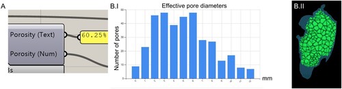
A.4.2. Pore sizes distribution
Using the Boolean intersection and Boolean difference operations, between the solid scaffold geometry, the individual cells and the final porous scaffold geometry, the individual pores can be isolated. This allows the calculation of pore size distribution which is seen in (B.I), which is another output of the Evaluation module. For the Voronoi scaffold the isolated pores can be seen in green in (B.II). As pores can have different shapes depending on the type of porous architecture used, the pore diameter is calculated by calculating the diameter of a sphere which has an equal volume to the arbitrary shaped pore. Hence, this is termed as ‘effective pore diameter’. However, the diameter of the largest sphere that would fit in these irregular pores also can be calculated if that is the preferred approach by the team of surgeons or design engineer.
A.4.3. Virtual insertion
The ‘Virtual Insertion’ module allows the virtual cross-sectional examination of the patient-specific fit. The scaffold and the bone defect can be sectioned by any user-set plane and the cross-section can be seen. In this view, a number slider enables the translation of the scaffold geometries (either the solid or porous) along its respective surgical approach vector. The design engineer would be able to inspect both the patient-specific fit and the unobstructive insertion of the scaffold by examining several cross-sectional planes. This cross-sectional examination for the femoral bone defect can be seen in (A).
A.4.4. 3D printability check
Finally, the 3D printability check includes a C# script which utilises the ‘mesh check’ functions of Rhinoceros 3D which are exposed via their C# API, named ‘RhinoCommon’. This function checks a given surface mesh that is either composed of quads, triangles or a combination of both, for self-intersected faces, degenerated faces, manifold edges and if the mesh is closed (watertight).
A.5. Export surface mesh
This module uses the level set to mesh conversion functionality offered by OpenVDB to convert any level set into a polygonal surface mesh, with or without adaptivity.
