
 ?Mathematical formulae have been encoded as MathML and are displayed in this HTML version using MathJax in order to improve their display. Uncheck the box to turn MathJax off. This feature requires Javascript. Click on a formula to zoom.
ABSTRACT
Single-nozzle based multimaterial direct ink writing enables voxel-based fabrication with superior printing efficiency than multi-nozzle protocol. This is attractive for food 3D printing process where efficiency matters for its application. However, for single-nozzle based process, the presence of residual material in the shared channel can affect its printing fidelity. In this study, we propose a path planning algorithm that can address this issue by incorporating (i) advance distance to compensate the extrusion delay when switching materials, and (ii) in-process printhead motion adjustments to stabilise the extrusion process. Our approach demonstrated a substantial improvement in printing fidelity, where the switching point offset was reduced to ±0.5 mm. Similarly, the unstable extrusion behaviours (bulging and necking) during switching materials were suppressed, where the printing fidelity was improved by 27 ± 5% (bulging) and 19 ± 3% (necking) respectively. Additionally, we provide an open-source slicing programme that empowers users to implement the above two algorithms.
Introduction
Additive Manufacturing (AM), also known as 3D printing, has demonstrated significant potentials for creating bespoke and programmable devices in recent years [Citation1–3]. Among its applications, 3D food printing (3DFP) has attracted considerable interest [Citation4,Citation5] for its ability to create customised foods with appealing geometries [Citation6–8], enhanced sustainability [Citation9–13], as well as functional foods designed for specific dietary needs [Citation14–17]. This technology is particularly attractive for its potential to control the spatial distribution of ingredients ((b)) like salt [Citation18] and sugar [Citation19], thereby allowing for reduced intake of these substances without significantly compromising taste [Citation20–23]. Such innovations in 3DFP can potentially assist consumers in managing health conditions such as diabetes [Citation24], metabolic syndrome [Citation25] and cardiovascular disease [Citation26,Citation27]. Direct ink writing (DIW), an extrusion-based method [Citation28], is widely recognised as the most effective technique in 3DFP research [Citation4]. Existing 3DFP methods often use multiple nozzles to control ingredient distribution, which can be inefficient due to high material switching times ((c)), increased equipment costs, and the need for precise calibration of extruder offsets in printers with multiple extruders [Citation7,Citation8]. To address these challenges, we have adopted a printhead design that incorporates two input channels and one shared nozzle, facilitated by a microfluidic chip-like printhead ((a)). This design, initially proposed by J.A. Lewis et al. [Citation29], significantly improves the printing speed of complex multimaterial structures [Citation29–31]. It allows for in-process material switching through a shared nozzle, effectively reducing switching times and simplifying machine operation.
Figure 1. (a) Schematic of single-nozzle based MM-DIW printhead design for food 3D printing; (b) exemplar of using MM-DIW to fabricate food with customised ingredient designs; (c) Comparison of printing efficiency between dual-nozzle and single-nozzle based MM-DIW process; (d) The shared channel and residual material at the switching point in single nozzle based MM-DIW; (e) Schematic of unoptimised path and the corresponding printed chessboard; (f) Schematic of defects caused when switching between materials of different viscosity; (g) Printed logo pattern with unoptimised path; (h) Printed pattern with optimised path.
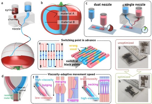
However, the single-nozzle method still has challenge: when different materials pass through the shared nozzle channel, residual material from previous extrusions ((d)) can cause delays and inaccuracy in the deposition of the other material ((e)). Furthermore, materials with differing rheological properties require distinct extrusion pressures and printhead movement speeds, leading to complications at material switching points ((f)). Lee et al. [Citation32] in their recent manuscript looked into some of these challenges and suggested these issues can significantly disturb the printing fidelity, resulting in disagreements between the final printed product and its intended design, and the printed part failure such as pattern discrepancy or ingredients cross-contamination.
To overcome these challenges, this paper investigates the underlying defects and introduces a model based strategy to mitigate these errors. Our approach includes the implementation of calculated advance distance at material switching points to offset extrusion delays, and the adjustment of printhead movement speed to align with real-time flow rates, thereby addressing flow instability when switching materials. Recognising the absence of existing slicing strategies that incorporate the above two optimisations, we propose an integrated slicing strategy that encompasses both solutions. Through the application of our method, we demonstrate effective suppression of these errors, significantly enhancing the accuracy and reliability of single-nozzle multimaterial DIW printing, making it more suitable for 3DFP process ((g,h)).
Results and discussion
Considering the different rheological properties of the two printing materials, we developed a physical model to calculate the theoretical advance distance at switching points to compensate the delay caused by material residues. This model was validated through the printing of chessboard patterns, achieving an enhanced printing fidelity of 0.1 mm (Section 2.1). We then extended our model to calculate adaptive movement speed required for more stable extrusion flow during material switching (Section 2.2). And we proposed a slicing strategy that incorporates both factors, enabling improved 2D patterns and 3D geometries using the single-nozzle MM-DIW process (Section 2.3). Finally, we present the practical applications of the optimised algorithm through the printing of various complex patterns and geometries (Section 2.4).
Advance distance compensation to offset extrusion delay
As previously mentioned, residual material in the shared channel when switching materials can cause extrusion delays, preventing the target material from being deposited accurately at the planned positions. This issue is particularly noticeable when printing small-sized multimaterial features, where frequent and accurate material switching is necessary. To mitigate this, we propose a path planning model that compensates for this delay, ensuring accurate material placement.
The advance distance can be calculated by Equation (1) because the segments
and
have the equal volumes during material switch ((a)),
(1)
(1) where
is the nozzle diameter,
is the shared channel length,
is the cross-sectional area of the deposited materials, and
is the length of extruded yet undeposited material.
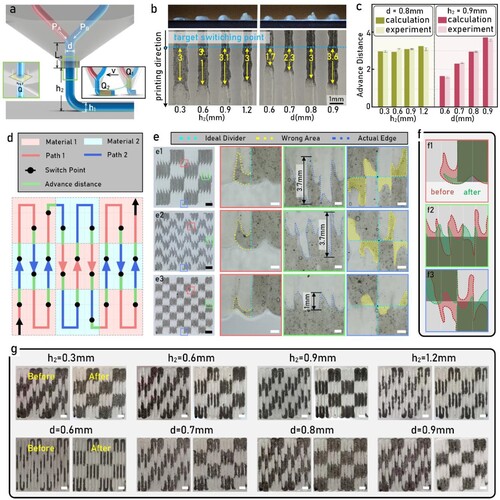
Figure 2. (a) Schematics of the nozzle outlet with the relevant dimensions labelled; (b) examples of the switching delay in the printing direction when printing with different nozzle heights; (c) comparison of the advance distance calculated theoretically and obtained experimentally with different combinations of nozzle heights and diameters
; mean ± standard deviation,
; (d) Schematic that explains how a chess board pattern was optimised with advance distance; (e) Printed chessboards with and without optimisation: (e1) unoptimised chessboard in unit of
; (e2) unoptimised chessboard in unit of
; (e3) optimised chessboard in unit of
; Black scale bars, 3 mm; White scale bars, 500 μm; (f) Detailed comparison of the printed chessboards in unit of
; (g) Printed chessboards with different nozzle heights, diameters; Scale bars, 2 mm.
Considering the hanging material results in material deposition delay when the nozzle height is greater than the print height
, the length
can be calculated by Equation (2).
(2)
(2) The cross-sectional area
in Equation (1) can be calculated by
(3)
(3) where
is the printhead movement speed, and
is the extrusion flow rate and can be calculated based on Poiseuille’s law [Citation33] as Equation (4)
(4)
(4) where
is the driven pressure on the material inside shared channel, and
is the material viscosity.
Note that (i) the extrusion material was considered as Newtonian fluids because the shear rate during the extrusion printing process remains ca. 104 ± 8 s−1 and the material viscosity has only 6% deviation (see details in the supplementary information), and (ii) the pressure on the material inside shared channel can be experimentally measured (Supplementary Data Fig. 2a).
To validate the above model, we conducted a series of experiments using two coloured inks to investigate the improvement effect of advance distance on extrusion delay when using different nozzle heights (0.3, 0.6, 0.9, 1.2 mm) and diameters (0.6, 0.7, 0.8, 0.9 mm) ((b)). The theoretical deposition delay values (the distance between the switching and deposition points) based on our model are within ±5% of the experimentally measured ones ((c)).
Then, advance distance was integrated into printing chessboard patterns ((d)). We printed two types of chessboards with different single unit width (10 × 10 for (e1) and 5 × 5 for (e2 and e3)). The figures with red outline showcased the printing errors when the switching point was at the edge of the pattern. The figures with green outline detailed the interface error between two chessboard units when the switching point was in the pattern. The figures with blue outline detailed deposition error at the intersections of four chessboard units. (e1 and e2) were both the results with unoptimised printing paths. It can be found that when the chessboard unit is large, it showed relatively good fidelity at macro scale. However, in terms of the local detail maps, they have the same level error (2.7 ± 0.5 mm). (e2 and e3) showed the results before and after optimisation, and it was evident that the optimised results had better reproduction in local details and smaller error (±0.5 mm). Subsequently, we overlaid the details of the two ((f)) to compare the area difference between the design and printed pattern, and the optimised strategy showed considerably reduction of the error by 73%, 66% and 70%, respectively. In addition, when using different nozzle heights and diameters, it was also found that the printing fidelity was improved by introducing the advance distance ((g)). This indicated that our method was compatible to different printing conditions.
This improvement is particularly significant in minimising the deviation between the intended deposition points and the actual results. The resulting print fidelity, especially in intricate patterns and small-sized features, shows a remarkable improvement in fidelity, affirming the importance of advance distance calculations in the optimisation of single-nozzle multimaterial direct ink writing.
Printhead speed compensation to avoid extrusion instabilities
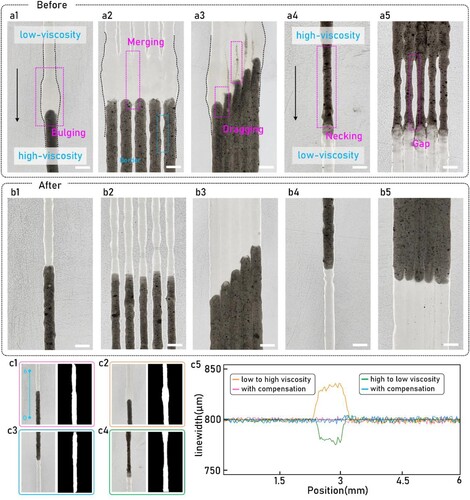
The over-extrusion-induced bulging occurs when switching from a low- to high-viscosity material due to the residual material in the shared channel, while the under-extrusion-induced necking in the reverse scenario ((b)). An ideal solution can be a pneumatic system capable of real-time adjusting extrusion pressure but with costly hardware. The more practical solution is to fix extrusion pressure while adaptively control the printhead speed .
The cross-section area of the print (symbolised by ) should be a fixed value so as to keep the printing fidelity. Therefore, the time-dependent printhead speed
is directly proportional to the instantaneous flow rate
as Equation (5)
(5)
(5) Based on Poiseuille’s law [Citation33], the instantaneous flow rate
can be calculated by Equation (6)
(6)
(6) where
and
are separately the viscosities and the instantaneous volume percentages of the current and the next material, and
is the driven pressure of the next material.
The instantaneous volume percentages in Equation (6) is related with the extruded material volume
as Equation (7)
(7)
(7) Based on the physical definition, the instantaneous volume
can also be obtained by integrating the flow rate
from zero (referring to the starting point) to a certain material switch moment
as Equation (8)
(8)
(8) where the maximum material switch period
can be calculated as Equation (9)
(9)
(9) where
is the volume of the shared channel, and the two the variables
and
are separately
(10)
(10)
(11)
(11) By combining Equations (6–8), the time-dependent flow rate
can be
(12)
(12)
Considering the standard G-code based numerical systems control motions via discrete movement speed for each command line, the equivalent average material extrusion flow rate for a discrete step can be expressed as
(13)
(13) where
is the timestep for each discrete control cycle.
Therefore, the final time-dependent printhead speed adaptive to different material viscosities used in each discrete numerical control cycle can be
(14)
(14) Using the models described above, we tested five printing cases involving switches between two fluids of different viscosities ((b1)). (a) shows the unoptimised performance with bulging ((b1)) and necking ((b4)). With our adaptive movement speed strategy, these effects were significantly reduced, and side effects such as unwanted merging ((b2)) or dragging ((b3)) were also addressed. Image processing methods were used to detect linewidth variations ((c)). The results showed that the linewidth in unoptimised paths fluctuated between 776 and 831 µm, while optimised paths maintained a more consistent linewidth of around 800μm. Thus, our optimisation significantly improved print fidelity during material switching, reducing linewidth fluctuations to 10 μm.
Figure 3. (a) Printing defects associated with switching between materials of different visocisties: a1 shows bulging at a transition from low to high viscosity without speed compensation; a2 illustrates merging defects at borders; a3 highlights dragging defects; a4 depicts necking during a transition from high to low viscosity; a5 shows a gap due to insufficient material flow; scale bars, 1 mm; (b) Resolved printing defect of print with compensated printing speed. b1–b5 depict the improved uniformity and reduction of defects as a result of adjusting print speed in accordance with material viscosity changes; Scale bars, 1 mm; (c) Linewidth comparison. c1–c2 illustrate the linewidth when transitioning from low to high viscosity, c3–c4 shows the reverse. c5 quantitatively presents the linewidth variations with respect to the position.
Path generation strategy
While we have developed strategies to mitigate unwanted effects in single-nozzle MM-DIW processes, no existing slicing software incorporates these considerations. Therefore, we also developed a multimaterial slicing software that integrates our strategies.
First, multimaterial 3D models or 2D images are preprocessed. For 3D models in assembly format (typically.step files), this involves exporting each material component in STL format, recording the minimum coordinates in each axis of the assembly’s coordinate system ((a1)), voxelising the model using a ray-casting algorithm, assigning material types to voxels ((a2)), and arranging the model into a three-dimensional array for layer-by-layer export ((a3)). For 2D images in formats like .jpg, .png, or .bmp, we perform resizing via Bilinear Interpolation Algorithm [Citation34], followed by binarisation to map the image to a bitmap format based on predefined thresholds ((b2)). In cases of multiple materials, additional rules map types by setting diverse threshold ranges and adjusting RGB values for pixels within those ranges while enhancing visualisation.
Figure 4. Flowchart that explains the path generation strategy: (a) Process of importing dual-material 3D model; (b) Process of importing dual-material 2D image. (c) Transformation from coordinate system to
;( d) Schematic of initial path; (e) Introduction of material type, different colours correspond to different materials; (f) Path with advanced switching points, green path indicates switching in advance; (g) Speed heatmap with adaptive movement speed.
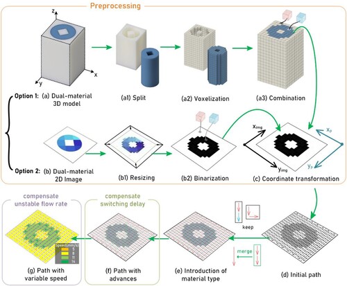
Next, we align the coordinate systems between the printing system and the imported data, which may require rotation or flipping ((c)). An initial path is generated to traverse the entire 2D array ((d)), with material types assigned to the correlated path for printing. Adjacent paths with the same direction and material type are merged for computational efficiency ((e)).
Finally, switching points are advanced based on the calculated distance, and corresponding speeds are assigned to paths within a certain distance before these points. This comprehensive slicing strategy addresses the challenges of integrating complex 3D models and 2D images, enabling real-time material switching during printing with a focus on high-precision results.
Vaseline based exemplars with the algorithm optimised printing parameters
Using our algorithm, we tested three different 2D patterns ((a–c)). For the University of Nottingham logo, we observed that the details of the letters and small features in the castle were well-reproduced, with minimal distortion. However, some distortion was still observed in the vertical direction due to the tailing effect during material switching. We also printed two other patterns: one with repeated and regular features ((b)) and another with fully randomised features ((c)). In both cases, features as small as 1 mm were accurately reproduced, though vertical fidelity was slightly compromised due to the tailing effect.
Figure 5. Exemplars of both 2D and 3D structure prints with the slicing software that considered advance distance and in-line adjusting nozzle speed. (a) Logo of University of Nottingham; Scale bars, 10 mm; (b) 2D print of repeat pattern; Scale bars, 10 mm; (c) 2D print of random patterns; Scale bars, 10 mm; (d) 3D cube with black and white voxels; Scale bars, 4 mm; (e) 3D pyramid with black & white voxels; Scale bars, 4 mm.
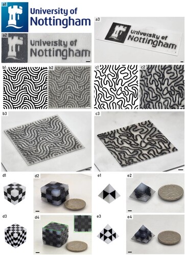
The fidelity of the prints was assessed using computer image processing, comparing the target and actual print results. The error for the repeated pattern ((b)) was only 2.2%, while the error for the random pattern ((c)) was 3.6%.
Furthermore, four 3D models (two cubes and two pyramids) were designed and printed to demonstrate our protocol’s performance with 3D structures. Models d3 and e3, with smaller voxel sizes, demanded higher printing precision and fidelity. The results showed that all four structures were successfully printed. The errors for the 5 × 5 cube were 1.5%, 2.1% and 0.7% higher than the 3 × 3 cube at the top, front and right sides, respectively. The pyramid structure with smaller voxels also showed larger errors (1.5% and 0.5% for the front and right sides) compared to the one with larger voxels.
Food-based exemplars with the algorithm optimised printing parameters
To demonstrate the efficacy of our proposed algorithm for 3DFP printing, we developed several extrudable edible formulations and tested our system by printing various creative structures.
We began with 2D examples, successfully printing the University of Nottingham logo using mashed potatoes and ketchup. The choice of these materials was intended to show that the printing strategy can handle substances with varying viscosities ((a)). The viscosity of the mashed potatoes was 3.17 Pa·s at 102 s−1 shear rate, while the modified ketchup had a viscosity of approximately 1.41 Pa·s at the same shear rate. Both mashed potatoes [Citation35,Citation36] and ketchup [Citation7] were adjusted to meet the extrusion and structural stability requirements of 3DFP. Comparative results indicate that our path planning algorithm significantly improves print quality: unoptimised results showed pattern irregularities due to switching delays, as well as visible over-extrusion and under-extrusion issues, leading to bulging and gaps during material transitions. In contrast, the optimised results displayed clear patterns and an effective blend of the two materials, demonstrating the reliability of our printing method.
Figure 6. Exemplars of 2D and 3D food structure printing with the proposed strategy. (a) University of Nottingham Logo printed with and without our optimisation strategy; Scale bars, 10 mm; (b) and (c) are artistic 2D patterns to demonstrate its application in plate decorating (b) Random pattern; Scale bars, 10 mm; (c) Repeated pattern; Scale bars, 10 mm; (d) 3D food printing of a cube with geometric lines; Scale bars, 10 mm; (e), (g) and (f) are exemplars that demonstrate the use of spatial salt level control to optimise their distributing aiming for healthier food with reduced salt and similar taste: (e) Cube with alternating slices; Scale bars, 6 mm; (f) Cube of concentric squares; Scale bars, 6 mm; (g) Cube with distributed mini-cubes; Scale bars, 6 mm.
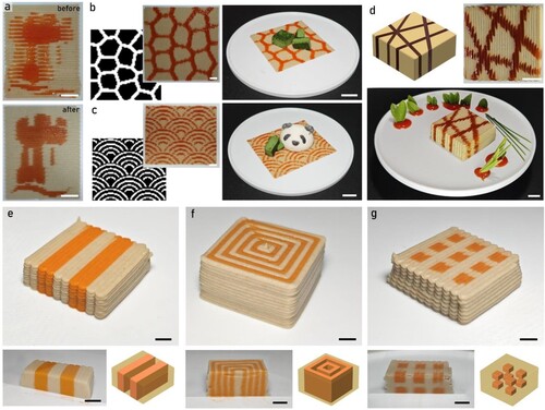
We applied the algorithm to create artistic food patterns for plate decoration. We showcased a random pattern ((b)) and a repeated pattern ((c)), demonstrating that our method can creatively enhance the visual appeal of dishes. This visual appeal was also evident in 3D structures, such as a designed cube ((d)). The geometric lines of the ketchup embedded in the mashed potato highlighted the printing precision and the ability to create complex designs that are challenging with traditional cooking methods, underscoring the potential of 3D food printing as a valuable tool for modern culinary practices, offering chefs and food scientists new avenues for innovation.
Despite these artistic applications, our printing strategy and algorithm also facilitate the creation of smart and healthier food options. Research has shown that it is possible to enhance taste perception by designing a spatially inhomogeneous distribution of ingredients within food products [Citation18,Citation20–23]. With carefully designed structures, it is possible to reduce the salt content by up to 30% [Citation23] while maintaining a comparable taste profile. Drawing on existing literature, we designed and printed three different heterogeneous geometries: a cube with alternating slices ((e)), a cube of concentric squares ((f)) and a cube with distributed mini-cubes ((g)). To print these exemplars, two mashed potato formulations with varying salt levels (1% w/w and 0%) were prepared and orange colourant (0.01% w/w) was added to the salt-containing formulation for introducing visual differentiation.
All printed structures were cross-sectioned to display their internal structure, confirming that both the appearance and internal structures were successfully fabricated. These examples illustrate the capabilities of our protocol, and we expect that the tools described in this paper will provide food scientists a toolset with greater design freedom, allowing for smarter food production with fewer concerns about the capabilities and efficiency of the printer.
Conclusions
In this paper, we have introduced a physical model-based path planning algorithm designed to enhance the printing fidelity of single-nozzle based Multimaterial Direct Ink Writing (MM-DIW), making it more suitable for 3DFP process. This was achieved by incorporating advance distance calculations and real-time adjustments to nozzle movement speed in order to address issues related to delayed deposition and extrusion flow instability when switching between different materials. Furthermore, we have provided an open-source software solution that accounts for both of these critical factors during the slicing process. Through comprehensive experimentation involving both 2D and 3D sample printing, our method demonstrated an improvement in printing fidelity, yielding an approximately 29 ± 11% enhancement. We believe our approach and accompanying protocol have the potential to contribute to the advancement of 3DFP processes, offering users effective toolset to address the relevant printing challenges.
Disclosure statement
No potential conflict of interest was reported by the author(s).
Data availability statement
The code that support the findings of this study are openly available in digital commons data at https://doi.org/10.17632/t35dgnmkrf.1
.Additional information
Funding
References
- He YF, et al. Exploiting generative design for 3D printing of bacterial biofilm resistant composite devices. Adv Sci. 2021;8(15).
- He YF, et al. A reactive prodrug ink formulation strategy for inkjet 3D printing of controlled release dosage forms and implants. Adv Ther. 2020;3(6).
- Wang R, et al. Direct 4D printing of ceramics driven by hydrogel dehydration. Nat Commun. 2024;15(1).
- Voon SL, An J, Wong G, et al. 3D food printing: a categorised review of inks and their development. Virtual Phys Prototyp. 2019;14(3):203–218. doi:10.1080/17452759.2019.1603508
- Ling KCL, Yee AZH, Leo CH, et al. Understanding 3D food printing technology: An affordance approach. Mater Today Proc. 2022;70:622–626. doi:10.1016/j.matpr.2022.08.564
- Pant A, Zhang Y, Kai Chua C, et al. 3D food printing – Asian snacks and desserts. Mater Today Proc. 2022;70:611–615. doi:10.1016/j.matpr.2022.08.563
- Liu ZB, Zhang M, Yang CH. Dual extrusion 3D printing of mashed potatoes/strawberry juice gel. LWT. 2018;96:589–596. doi:10.1016/j.lwt.2018.06.014
- Hertafeld E, Zhang C, Jin Z, et al. Multi-material three-dimensional food printing with simultaneous infrared cooking. 3d Print Addit Manuf. 2019;6(1):13–19. doi:10.1089/3dp.2018.0042
- Wong GHC, Pant A, Zhang Y, et al. 3D food printing– sustainability through food waste upcycling. Mater Today Proc. 2022;70:627–630. doi:10.1016/j.matpr.2022.08.565
- Tan JD, et al. 3D printability and biochemical analysis of revalorized orange peel waste. Int J Bioprinting. 2023;9(5):510–521.
- Leo CH, Lee CP, Foo SY, et al. 3D printed nutritious snacks from orange peel waste. Mater Today Proc. 2022;70:12–16. doi:10.1016/j.matpr.2022.08.484
- Lee CP, Takahashi M, Arai S, et al. 3D printing of okara ink: the effect of particle size on the printability. ACS Food Sci Technol.. 2021;1(11):2053–2061. doi:10.1021/acsfoodscitech.1c00236
- Da Tan J, Lee CP, Leo CH, et al. Enhancing three-dimensional (3D) printablity of durian husk inks. Mater Today Proc. 2022;70:698–702. doi:10.1016/j.matpr.2022.10.126
- Zhang Y, et al. Systematic engineering approach for optimization of multi-component alternative protein-fortified 3D printing food ink. Food Hydrocoll. 2022;131.
- Pant A, Lee AY, Karyappa R, et al. 3D food printing of fresh vegetables using food hydrocolloids for dysphagic patients. Food Hydrocoll. 2021;114:106546. doi:10.1016/j.foodhyd.2020.106546
- Lee CP, Karyappa R, Hashimoto M. 3D printing of milk-based product. RSC Adv. 2020;10(50):29821–29828. doi:10.1039/D0RA05035K
- Karyappa R, Hashimoto M. Chocolate-based ink three-dimensional printing (Ci3DP). Sci Rep. 2019;9:14178. doi:10.1038/s41598-019-50583-5
- Sun CX, et al. Food and salt structure design for salt reducing. Innov Food Sci Emerg. Technol. 2021;67.
- Deliza R, Lima MF, Ares G. Rethinking sugar reduction in processed foods. Curr Opin Food Sci. 2021;40:58–66. doi:10.1016/j.cofs.2021.01.010
- Nakao S, Ishihara S, Nakauma M, et al. Inhomogeneous spatial distribution of aroma compounds in food gels for enhancement of perceived aroma intensity and muscle activity during oral processing. J Texture Stud. 2013;44(4):289–300. doi:10.1111/jtxs.12023
- Noort MWJ, Bult JHF, Stieger M. Saltiness enhancement by taste contrast in bread prepared with encapsulated salt. J Cereal Sci. 2012;55(2):218–225. doi:10.1016/j.jcs.2011.11.012
- Pflaum T, Konitzer K, Hofmann T, et al. Influence of texture on the perception of saltiness in wheat bread. J Agric Food Chem. 2013;61(45):10649–10658. doi:10.1021/jf403304y
- Li YL, et al. Salt reduction in semi-solid food gel viinhomogeneous distribution of sodium-containing coacervate: effect of gum arabic. Food Hydrocoll. 2020;109.
- Lang A, Kuss O, Filla T, et al. Association between per capita sugar consumption and diabetes prevalence mediated by the body mass index: results of a global mediation analysis. Eur J Nutr. 2021;60:2121–2129. doi:10.1007/s00394-020-02401-2
- Evans CEL. Sugars and health: a review of current evidence and future policy. Proc Nutr Soc. 2017;76(3):400–407. doi:10.1017/S0029665116002846
- Xue YZ, Wen Q, Xu C, et al. Elevated salt taste threshold Is associated with increased risk of coronary heart disease. J Cardiovasc Transl Res. 2020;13(6):1016–1023. doi:10.1007/s12265-020-10017-4
- Garfinkle MA. Salt and essential hypertension: pathophysiology and implications for treatment. J Am Soc Hypertens. 2017;11(6):385–391. doi:10.1016/j.jash.2017.04.006
- Lewis JA. Direct ink writing of 3D functional materials. Adv Funct Mater. 2006;16(17):2193–2204. doi:10.1002/adfm.200600434
- Skylar-Scott MA, Mueller J, Visser CW, et al. Voxelated soft matter via multimaterial multinozzle 3D printing. Nature. 2019;575(7782):330–335. doi:10.1038/s41586-019-1736-8
- Hardin JO, Ober TJ., Valentine AD., et al. Microfluidic printheads for multimaterial 3D printing of viscoelastic inks. Adv Mater. 2015;27(21):3279–3284. doi:10.1002/adma.201500222
- Hassan I, Selvaganapathy PR. Microfluidic printheads for highly switchable multimaterial 3D printing of soft materials. Adv Mater Technol. 2022;7(9):2101709. doi:10.1002/admt.202101709
- Lee CP, et al. Multi-Material extrusion 3d food printing using multi-channel nozzle. Chian and Hashimoto, Michinao. https://papers.ssrn.com/sol3/papers.cfm?abstract_id=4698284
- Sutera SP, Skalak R. The history of Poiseuille’s law. Annu Rev Fluid Mech. 1993;25(1):1–20. doi:10.1146/annurev.fl.25.010193.000245
- Gonzalez R, Wintz P. Digital image processing. 2nd ed. Reading (MA): Addison Wesley; 1987.
- Liu ZB, Bhandari B, Prakash S, et al. Creation of internal structure of mashed potato construct by 3D printing and its textural properties. Food Res Int. 2018;111:534–543. doi:10.1016/j.foodres.2018.05.075
- Liu ZB, Zhang M, Bhandari B, et al. Impact of rheological properties of mashed potatoes on 3D printing. J Food Eng. 2018;220:76–82. doi:10.1016/j.jfoodeng.2017.04.017