
 ?Mathematical formulae have been encoded as MathML and are displayed in this HTML version using MathJax in order to improve their display. Uncheck the box to turn MathJax off. This feature requires Javascript. Click on a formula to zoom.
ABSTRACT
This study employed the effect of sub-critical annealing heat treatment on the microstructure and anisotropy of the hybrid additive manufactured TC11 alloy. The results demonstrate that after sub-critical annealing, a gradient microstructure with the gradual changes in the morphology and content of primary α phases from the laser deposition zone to the substrate zone was formed. Moreover, the tensile anisotropy of the hybrid manufactured specimens was substantially reduced. In particular, when loading along to the deposition direction, the ultimate tensile strength of the heat-treated hybrid manufactured specimen was 1062 MPa, increased by 8.5%. And when loading perpendicular to the deposition direction, the elongation can reach 13.0%, increased by 86% compare to the as-deposited sample. These findings would also shed new insights for the modification of graded structural parts prepared by the hybrid manufacturing technique, laser additive repair and other methods.
1. Introduction
Due to the good toughness, superior specific strength and high corrosion resistance, titanium and its alloys have achieved broad application in load-bearing structures with complex geometry, such as aerospace, petrochemical and marine engineering [Citation1–5]. Whereas, the structural complexity and processing volume make it challenging and limited to directly produce large integral structures by a single manufacturing process. Consequently, to overcome these difficulties, a new hybrid manufacturing technique integrating the conventional processing techniques and additive manufacturing technologies has been developed [Citation6–10]. This approach can take full advantage of the high performance and flexibility of directed energy deposition (DED) technology as well as the efficiency [Citation11–16] and low cost of traditional forging or rolling components.
Although the hybrid technique shows considerable promise for producing high performance complex structures, regulating the microstructure still presents certain challenges. On the one hand, in the laser deposition zone (LDZ), the as-deposited titanium alloys usually show the epitaxial growth of coarse β columnar crystal and intragranular lamellar (α+β) basketweave microstructures [Citation17, Citation18]. The fine lamellar microstructures in the LDZ typically show high strength, poor plasticity and anisotropy, making it becomes the weak zone of the whole hybrid manufactured structure [Citation19]. For example, Chi et al. [Citation20] and Bambach et al. [Citation21] both reported that the hybrid manufactured titanium alloys were fractured at the LDZ side during tensile process. Our previous research has also presented that during the plastic deformation of the bonding zone sample, microcracks preferentially forming at the grain boundaries in the LDZ and gradually expanding to the substrate result in final fracture [Citation22]. On the other hand, the successive heating/cooling effects of the DED process on the substrates during the hybrid manufacturing technique could lead to the formation of the heterogeneous microstructures in the heat affected zone (HAZ), which would affect the performance of the final parts [Citation23, Citation24]. For instance, Ling et al. [Citation25] reported that the HAZ had the worst plasticity and toughness in the hybrid manufactured TC4 sample. Shen et al. [Citation26] studied the tensile deformation behaviour of the TC17 titanium alloy formed by the hybrid manufactured technique and the results revealed that owing to the poor coordinated deformation among grains, the stress concentrated firstly in the HAZ. Consequently, the above questions of the hybrid manufactured titanium alloys in the as-deposited state limit its applications.
Heat treatments have been proved to be a feasible method to tune the final microstructure and adjust the mechanical properties [Citation27–30]. Many studies have shown that the mechanical properties of the additive manufactured titanium alloys can be significantly improved after the sub-critical annealing at a temperature that slightly lower than the βtrans temperature [Citation31–33]. During this heat treatment, the residual primary α (αp) phases grow and coarsen, which are conductive to increasing the plasticity, and the ultrafine secondary α phases (αs) would precipitate from the β phases leading to the improved strength. The combined effect of multiscale α phases can achieve a good match between the strength and plasticity of titanium alloys. For example, Zhao et al. [Citation34] spheroidized the α phases in the laser DEDed TC4 titanium alloy using the sub-critical annealing treatment, resulting in a great increase in the elongation accompanied with a slight decrease in strength within in an acceptable range. Similarly, Zhang et al. [Citation35] proposed that the strength and ductility of the DEDed TA15 titanium after sub-critical annealing heat treatment were simultaneously increased by about 13 MPa and 4.4%, respectively. However, few studies have systematically investigated the effects of heat treatment on the microstructures and mechanical performance of the hybrid manufactured titanium alloys with gradient structures. And it is not clear whether a single heat treatment schedule can meet the optimal strengthening conditions of the multiple components simultaneously. Therefore, there is necessary to design a heat treatment suitable for the hybrid additive manufactured titanium alloys, and study the effects of heat treatment on the microstructures and mechanical properties in detail.
In this study, the effect of heat treatment on the microstructure evolution as well as the tensile mechanical properties of the hybrid manufactured TC11 titanium part were investigated. The microstructural characteristics of the hybrid manufactured samples were analyzed in detail before and after sub-critical annealing treatment using different microscope techniques. The influence of heat treatment on the mechanical performance was evaluated by uniaxial tensile tests to uncover the relationship between microstructures and mechanical properties. Digital image correlation (DIC) and in-situ XRD tensile tests were also conducted to reveal the deformation behaviour of the heat-treated hybrid manufactured TC11 titanium alloy.
2. Experimental methods
2.1. Hybrid manufacturing process and heat treatment
The hybrid manufactured specimens were achieved by depositing the TC11 titanium alloy on the rolled plates. The spherical pre-alloyed TC11 powders for the laser DED process had an average size 177 ± 40 μm, as shown in (a). The deposition experiments were carried out using a self-developed DED system, which was equipped with an 8 KW fiber-coupled diode, a beam diameter of 6 mm, a computer numerical control multi-axis motion system, a coaxial powder feeding nozzle and an inert atmosphere protection chamber. During the DED process, the laser power was set at 3500 W, a powder feed rate of 16 g/min, a scanning speed of 1000 mm/min and the oxygen content was less than 50 ppm. The scanning strategy for forming TC11 bulk samples is shown in (a). Because the rolled substrates had three different directions including rolling direction (RD), normal direction (ND) and transverse direction (TD), for better analysis, the hybrid manufactured TC11 bulk specimens were deposited at the ND-RD and TD-RD planes, respectively, as depicted in (b). shows the chemical composition of the laser deposition zone and the substrate zone. Then the specimens were first annealed at 530 °C for 2 h to release the residual stress and it was marked as-deposited alloys. Before formulating the heat treatment schedule, the βtrans temperature of laser DEDed TC11 alloy was determined by the metallographic method and it was 1015 ± 5 °C. Thus, 990 °C was selected as the sub-critical annealing temperature. Specifically, a subset of the hybrid manufactured TC11 samples was sub-critical annealed at 990 °C for 1 h followed by 530 °C for 6 h. And the two cooling methods were air cooling (AC), as illustrated in (f). This heat treatment was indicated by the 990HT in this study.
Figure 1. (a) Powder characteristics and schematic illustration of the laser DED process. (b) Different TC11 bulk samples fabricated by hybrid manufacturing technique. (c) The relative positions of the metallographic samples and different kinds of tensile samples. (d) Schematic illustration of in-situ XRD tensile experimental setup. (e) Dimensions of rod-shaped specimens, DIC and in-situ XRD coupons, unit in mm. (f) The heat treatment path for the hybrid manufactured TC11 samples.
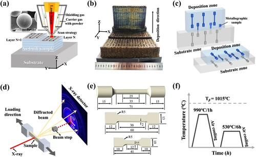
Table 1. Chemical composition of the LDZ and SZ (wt.%).
2.2. Metallographic characterisation
Metallographic samples of the hybrid manufactured TC11 alloy at different stages were cut through wire electrical discharge machining. These specimens were cut from the cross-section of the hybrid manufactured TC11 plate, as shown in (c). They were then ground, polished and etched using Kroll’s agent. The preliminary microstructures were observed using Digital Camera (Nikon D90), Optical Microscope (OM, Leica DM4000) and Scanning Electron Microscope (SEM, Apreo S Lovac). The phase content and size were calculated by Image J software. The texture evolution was analyzed by electron back-scattered diffraction (EBSD) with a field-emission source of 20 kV and a 1.5 μm step size through JSM-7001F (Pegasus XM2). Then the recorded data were processed using TSL OIM software and MATLAB toolbox Mtex-5.7.
2.3. Mechanical properties
According to whether it is along the deposition direction and the sampling location, five different kinds of rod-shaped tensile specimens including the deposition zone (D-L, D-T), the bonding zone (D + S-L, D + S-T) and the rolled substrate (S) were taken out from hybrid manufactured TC11 samples of the as-deposited and heat-treated states. It should be noted that the L and T represent the tensile direction parallel and perpendicular to the deposition direction, respectively. In order to reduce the measurement error, three rod-shaped tensile specimens of five types were performed in accordance with the GB/T228.1-2016 test standard. Besides, the tensile strain in the bonding zone of the heat-treated hybrid manufactured TC11 alloy was analyzed by means of the digital image correlation (DIC) tests. During the DIC experiment, two cameras took pictures every 400 ms to capture the gauge length. In-situ X-ray diffraction (XRD) measurement during the tensile deformation was also conducted to analyze the difference of deformation behaviour between the laser deposition zone and substrate of the D + S-L heat-treated sample. The experiment was carried out on an additional tensile apparatus equipped with a wide-angle XRD using the NANOPIX-WE system (Rigaku Co, Tokyo, Japan). The system was equipped with a rotating Mo anode target as an X-ray source (corresponding to a wavelength of λ, 0.7093 Å). (c) also shows the hybrid manufactured specimens and the positions where the rod-shaped samples, DIC and in-situ XRD coupons were extracted. (d) illustrates the schematic of in-situ XRD tensile experimental setup. The dimensions of each specimen are illustrated in (e). The gauge dimensions of the DIC and in-situ XRD coupons are 30 × 6 × 2 mm3 and 15 × 4 × 0.8 mm3, respectively.
3. Results
3.1. Microstructure characterisation
3.1.1. As-deposited specimen
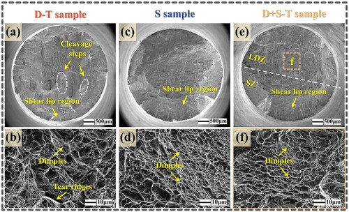
shows the microstructures of the as-deposited hybrid manufactured TC11 alloy. As displayed in (a), the as-deposited hybrid manufactured TC11 sample can be categorised into three zones: the laser deposition zone (LDZ) in the upper part, the heat affected zone (HAZ) in the middle and the substrate zone (SZ) in the lower part. No defects are found in these three zones of the sample. As illustrated in (a–c), the LDZ shows a columnar grain structure that penetrates multiple layers. And the average width of these columnar β grains is about 0.8 mm. Additionally, the microstructure within prior β grains of the LDZ shows a fine basket-weave structure includes continuous grain boundary α (αGB), parallel-arranged α colony and lamellar α. The total content and thickness of α phases are about 76.3% and 0.7–1.2 μm, respectively. For the HAZ, as (d) shows, in the region near the fusion line, recrystallization occurs and coarse equiaxed grains are formed due to the large heat input. Additionally, there are a lot of α colonies in these equiaxed β grains ((e)). More detailed microstructural characteristics in other regions of the HAZ and the microstructure formation mechanism can be found in our previous study [Citation22]. The microstructure of the SZ is indicated in (f–g), showing an elongated and streamlined grain morphology along the rolling direction, and the volume fraction of α phases is about 82%, which is slightly higher than that in the LDZ.
Figure 2. Microstructures of the as-deposited hybrid manufactured sample: (a) overview of the specimen composed by three different zones [Citation22]; OM and magnified SEM images for the (b)-(c) LDZ, (d)-(e) HAZ and (f)-(g) SZ, respectively.
![Figure 2. Microstructures of the as-deposited hybrid manufactured sample: (a) overview of the specimen composed by three different zones [Citation22]; OM and magnified SEM images for the (b)-(c) LDZ, (d)-(e) HAZ and (f)-(g) SZ, respectively.](/cms/asset/1a2a97bb-ca7d-4ae1-92e5-942cdd888c0b/nvpp_a_2382168_f0002_oc.jpg)
3.1.2. Microstructures after sub-critical annealing treatment
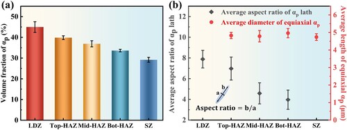
shows the microstructures of the heat-treated hybrid manufactured TC11 alloy. For the LDZ, after the 990HT heat treatment, the β grain morphology remain unchanged compare with that of the as-deposited sample, as shown in (a). It is consistent with the previous research results that when the peak temperature is lower than the βtrans temperature, columnar grains are observed to persist [Citation36]. However, the basket-weave structure within prior β grain transforms into a special bimodal structure that is composed of coarse αp laths with a width of about 1.6 μm along with ultrafine lamellar αs in the βtrans matrix, as revealed in (b). The αGB becomes discontinuous due to the high solution temperature near βtrans temperature, which promotes the dissolution of continuous αGB. In the SZ, the microstructure changed from a typical deformed elongated structure into the conventional bimodal microstructure in which the αp phases are nearly equiaxed due to the subsequent recrystallization ((c)). (d) shows the overall microstructure for the HAZ. And according to the distance from the fusion line, the HAZ can be subdivided into three different sub-regions: the top-HAZ, the middle-HAZ as well as the bottom-HAZ. SEM images of (e–g) present the detailed microstructural characteristics in these three subzones. On the whole, the αp laths, equiaxed αp and ultrafine βtrans exist simultaneously in the three regions of the HAZ, but the volume fraction and the average aspect ratio of the coarse αp phases are substantially change along the deposition direction. According to (a), the volume percentage of the αp phases gradually decreases from the LDZ (∼ 44.9%) to the SZ (∼ 29.1%). And in the HAZ, the volume fraction of the αp phases (including the αp laths and equiaxed αp phases) follow the sequence of top-HAZ > middle-HAZ > bottom-HAZ. It is possible to pinpoint that, as shown in (b), the average aspect ratio of the αp laths gradually decreases from the LDZ to HAZ, whereas the average diameter of the equiaxed αp phases maintain constant (∼ 4.6μm) in the HAZ and SZ.
Figure 3. Microstructures of the heat-treated hybrid manufactured sample: (a) overview of the specimen; (b)-(c) OM and magnified SEM images for the LDZ and SZ, respectively; (d) overall microstructural characteristics for the HAZ; (e)-(g) microstructures of the dotted box at the corresponding locations in (d).
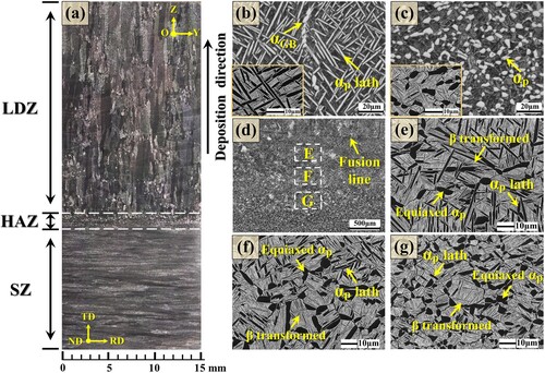
Figure 4. (a) The volume percentage of the αp phases and (b) the average aspect ratio of the αp laths and the average diameter of the equiaxed αp phases at different locations in the heat-treated hybrid manufactured TC11 alloy.
3.1.3. Crystallographic texture
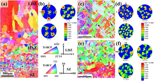
shows the inverse pole figure orientation maps and pole figures of the as-deposited hybrid manufactured TC11 sample. The observation of microstructure is on the YOZ and TD-RD cross sections for the LDZ and SZ, respectively. As presented in (a and b), the α phases show high texture strength in some certain directions of the LDZ. It can be ascribed to the strong β<001>// building direction texture formed during the laser scanning process and this fiber texture would transform into weak textured α phase strictly followed the Burgers orientation relationship [Citation37]. As shown in (c and d), in the SZ, some α grains present a texture state of (0002) basal plane is around 30° away from the perfect <0001 > texture [Citation38]. For comparison with the crystallographic orientation evolution of the hybrid manufactured samples before and after heat treatment. EBSD test is carried out on the heat-treated parts. As depicted in (a and b), the β phases in the LDZ of the 990HT sample also display the strong β<001>// building direction texture. It is consisted with the results of previous studies [Citation39, Citation40]. From the above αp phases measured results, after the 990HT heat treatment, there are still about 44.9% of the αp phases in the LDZ, and these uniformly distributed αp phases are theoretically the same as the texture of the as-deposited state. In addition, the precipitation of the αs phases also followed the Burgers orientation relationship. Therefore, the crystallographic textures of α orientations in the LDZ ((c, d)) are similar to the as-deposited sample. The inverse pole figure orientation maps and pole figures of the α phases in the SZ ((e, f)) indicated that the appeared textures of the α phases in rolled microstructure are maintained during the 990HT heat treatment process, but the maximum intensity of texture changes.
Figure 5. EBSD results of the as-deposited hybrid manufactured TC11 sample. (a) Reconstructed β-orientation map from the SZ to the LDZ and the corresponding (b) pole figures in the LDZ. Inverse pole figure orientation maps and pole figures of the α phases in the (c)-(d) LDZ and (e)-(f) SZ.
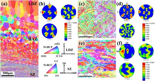
Figure 6. EBSD results of the heat-treated hybrid manufactured TC11 sample. (a) Reconstructed β-orientation map from the SZ to the LDZ and the corresponding (b) pole figures in the LDZ. Inverse pole figure orientation maps and pole figures of the α phases in the (c)-(d) LDZ and (e)-(f) SZ.
3.2. Mechanical properties
3.2.1. Tensile properties of the L-direction samples
The tensile performances of the L-direction as-deposited and heat-treated hybrid manufactured TC11 alloy are listed in . The ultimate tensile strength (UTS) of the 990HT D-L, D + S-L and S samples are all increased compared with the as-deposited samples, and the UTS of the D + S-L sample can reach 1062 MPa, which is increased by 8.5%. In terms of plasticity, both the elongation (EL) and reduce in area (RA) of the D-L, D + S-L samples in the heat-treated state are similar to that of the as-deposited state. In addition, the EL and RA of the S sample are slightly decreased with acceptable after the 990HT heat treatment.
Table 2. Room temperature properties of the as-deposited and heat-treated hybrid manufactured TC11 alloy with the L-direction.
In this study, the heterogeneous deformation behaviours of the heat-treated hybrid manufactured TC11 alloy are mainly studied. Thus, (a) also presented the detail engineering strain–stress curves of the 990HT D-L, D + S-L and S samples. It can be confirmed that the UTS (∼1178 MPa) and YS (∼1045 MPa) of the 990HT S sample are higher than those of the 990HT D-L and D + S-L samples. The UTS of the 990HT D + S-L sample is comparable to that of the 990HT D-L sample, while the 990HT D + S-L sample show a higher YS (∼921 MPa). In contrast, compared with the 990HT D + S-L and S samples, the 990HT D-L sample exhibit the highest EL (∼16.3%) and RA (∼31.0%). And the EL is about 10.6% of the 990HT D + S-L sample, which is a little lower than that of the 990HT S sample.
Figure 7. Tensile results of the L-direction heat-treated hybrid manufactured TC11 alloy. (a) Strain-stress curves of the heat-treated D-L, D + S-L and S samples. (b) Macroscopic image near the fracture and the crack propagate path within the β grains of the 990HT D + S-L sample. (c) DIC observations on deformation behaviours of the 990HT D + S-L sample over time.
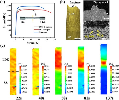
Subsequently, as shown in (b), the fracture position of the 990HT D + S-L specimen is located in the LDZ. The OM micrographs of the fracture profile, indicating that the crack propagation path is tortuous and behaves transgranular ductile fracture. The enlarged SEM image presents that the αp laths near the fracture has a large-scale deformation. (c) displays the strain evolution contour maps from elastic deformation stage to necking characterised by DIC analysis throughout the tensile process of the 990HT D + S-L sample. At the beginning of the tensile test (22 s), the cloud image shows that the whole specimen has uniform elastic deformation, which means that the LDZ, HAZ and SZ bear similar strain. With the progress of the tensile test subsequently, after 40 s, the inhomogeneous local strain concentration in the LDZ is more obvious than that in the HAZ and SZ. Then the strain is further concentrated between 40 and 81 s, and the whole sample undergoes significant deformation. After 81 s, the strain concentration is aggravated, and the obvious necking appears in the LDZ, which eventually leads to the fracture in this zone (137 s). Therefore, when the loading direction parallel to the deposition direction, the strength and plasticity of the LDZ are the kay factors affecting the performance of the 990HT D + S-L sample.
The in-situ XRD tensile results can quantitatively determine the lattice strains of different α phases crystal planes between the LDZ and SZ of the 990HT D + S-L sample during deformation. By calculating the evolution of lattice stress with applied stress, the load partitioning of α phases in different zones can be calculated. One-dimensional diffraction profiles are obtained along the tensile axis, that is., the integral range from −5 to +5° along the longitudinal direction, using the FIT2D software. Note that due to the texture of the LDZ and SZ, it is not achievable to acquire reliable d-spacing information for all α phases. Thus, in this analysis, {100}α, {10
1}α and {10
2}α planes with peak intensities are sufficient to fit are chosen for calculation.
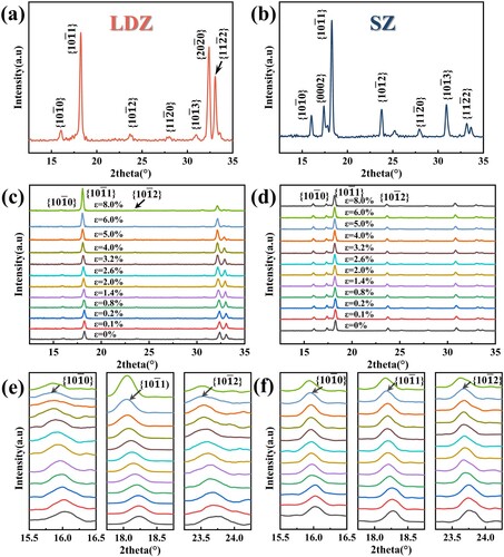
The 2D diffraction patterns in the LDZ and SZ of the 990HT D + S-L sample before deformation are shown in (a, b), and the diffraction peaks positions of these two zones are similar. More specifically, the diffraction peak of {0002}α disappears with peak intensity of {200}α increases in the LDZ compare with the peaks in the SZ. (c–f) display the evolution of the X-ray diffraction peaks positions in the LDZ and SZ of the 990HT D + S-L sample under different tensile strains. The diffraction peaks in the LDZ and SZ shift to the lower 2θ angle, indicating that along the tensile direction the dhkl is increased. Peak broadening is also observed of the two zones, especially in the late stage of deformation. Shifting and broadening of the diffraction peaks indicate the development of lattice strain and the accumulation of dislocations [Citation41]. On the whole, the shift of the {0002}α, {10
1}α and {10
1}α diffraction peaks in the SZ lags behind the shift of those peaks in the LDZ after 2% strain, and the variation of the diffraction peaks of {10
0}α is larger than that of the {10
1}α and{10
2}α in the LDZ and SZ ((e, f)).
Figure 8. The in-situ XRD tensile test results of the 990HT D + S-L sample. XRD profiles of the un-strained sample in the (a) LDZ and (b) SZ. Evolution of the X-ray diffraction peaks positions in the (c), (e) LDZ and (d), (f) SZ in different tensile strains along the loading direction.
The shifting of the diffraction peaks during the tensile process is generally caused by the lattice strain, and it is can be calculated using the equation below [Citation42],
(1)
(1) where
and
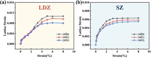
are the d-spacing of the {hkl} plane in phase i under applied stress σ and prior to loading, respectively. The lattice strain along the tensile direction can be calculated by the Eq. (1) and combined with the position of each {hkl} peak recorded in the real time during deformation. shows the evolution of the lattice strains along the tensile direction for {10
0}α, {10
1}α, {10
2}α in the LDZ and SZ. In the initial elastic deformation stage (before about 2% strain), the lattice strains of all peaks in the LDZ and SZ of the 990HT D + S-L sample increase linearly with the macroscopic strain. With the increase macroscopic of strain (2-4% strain), the lattice strain of the LDZ and SZ all increase slowly and after 4% macroscopic strain, the lattice strains tend to be stable in the two zones. According to the previous results [Citation43, Citation44] that after the end of elastic deformation, lattice strains increase slowly or remain stable of all {hkl} planes owing to the activation of dislocation slipping. Comparing the lattice strain values in , the {10
0}α, {10
1}α, {10
2}α phases in the SZ are yielded later than those in the LDZ, indicating that the yield and plastic deformation are occurred in the LDZ of the 990HT D + S-L sample. This phenomenon corresponds with the DIC results.
Figure 9. Evolution of the lattice strains in the (a) LDZ and (b) SZ of the 990HT D + S-L sample during the tensile deformation.
3.2.2. Tensile properties of the T-direction samples
The tensile performance of the different samples (D-T, D + S-T and S) of the as-deposited and heat-treated hybrid manufactured TC11 alloy are listed in . After sub-critical annealing heat treatment, in comparison with the as-deposited samples, the UTS and YS of the 990HT D-T and D + S-T samples are a little decrease, but they are all increased in the 990HT S samples. Moreover, the EL and RA are greatly improved in the 990HT D-T and D + S-T samples. In addition, the EL and RA of the 990HT D + S-T specimen can reach 13.0% and 29.0%, increased by 86% and 76%, respectively, which is comparable to that of the 990HT S sample.
Table 3. Room temperature properties of the as-deposited and heat-treated hybrid manufactured TC11 alloy with the T-direction.
The detail engineering strain–stress curves of the 990HT D-T, D + S-T and S samples are also displayed in (a). It should be noted that the UTS (∼1134 MPa) and YS (∼990 MPa) of the 990HT D + S-T sample are between those of the 990HT D-T and S samples. The result is consistent with the strength criterion of the typical metal laminated composites [Citation45, Citation46]. Furthermore, as shown in the true strain–stress curves of tension ((b), ignoring the necking errors), these curves at the elastic deformation stage present three stages. More specifically, stage I changes linearly, while stage II is nearly linear but with a reduced slope and stage Ⅲ varies nonlinearly. (c–h) show the microstructures of fracture profile in the different 990HT samples. The fracture mechanism of the 990HT D-T sample is transgranular, i.e. the crack passes through columnar grain boundaries resulting in an increase in plasticity. At the same time, the αp laths within the β grains near the fracture have undergone severe deformation. As for the 990HT S sample, the crack propagation path is more tortuous and the original equiaxed αp are elongated and deformed to a certain extent. While for the 990HT D + S-T sample, because the three zones including the LDZ, HAZ and SZ are deformed at the same time, the crack propagation path ((e)) is different from the former two types of samples, and it is observed that the deforming degree of the αp laths near the fracture in the upper LDZ ((h)) is more severe than that of the 990HT D-T sample. shows the fractures of the three different tensile samples. The macroscopic images ((a, c and e)) show that the shear lip region of the 990HT D-T sample is smaller than that of the 990HT S and D + S-T samples, which corresponds to the low plasticity of the 990HT D-T sample. In addition, the fracture surfaces of the 990HT D-T sample ((a, b)) show several cleavage steps accompanied with some dimples and tearing ridges, indicating a quasi-cleavage fracture mechanism. Furthermore, the large and deep dimple characteristics in (d and f) support the high plasticity of the 990HT S and D + S-T samples.
Figure 10. Tensile results of the T-direction heat-treated hybrid manufactured TC11 alloy. (a) Strain-stress curves of the 990HT D-T, D + S-T and S samples. (b) The elastic deformation stages of stress–strain curves of different samples. (c)-(e) OM and (f)-(h) SEM micrographs of cracks in the 990HT D-T, D + S-T and S samples, respectively.
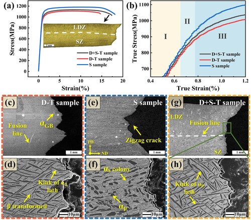
Figure 11. SEM images of the fracture for the different 990HT hybrid manufactured samples: (a)-(b) the D-T sample; (c)-(d) the S sample; (e)-(f) the D + S-T sample.
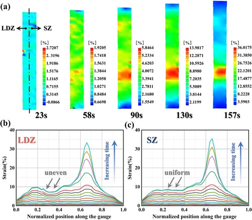
The tensile strain evolution results ((a–c)) measured by DIC of the 990HT D + S-T sample are used to further analyze the deformation behaviour in different zones. At the beginning of the tensile process (23 s), similar to the 990HT D + S-L sample, deformation occurs uniformly throughout the whole specimen. As the tensile test progresses (after 58 s), the strain in different zones of the sample began to differ. Specifically, the strain level at the LDZ (left) side is greater than that at the SZ (right) side. Moreover, as indicated in (b, c), the strain distribution from top to bottom at the LDZ (left) side is more uneven than that at the SZ (right) side. Different from the 990HT D + S-L sample that the strain is concentrated in the LDZ, the fracture position is random in the 990HT D + S-T sample. It can be seen from the DIC contour map that from 90 s to 157 s, the lower part of the 990HT D + S-T sample shows obvious stress concentration and necking phenomenon.
Figure 12. (a) DIC observations on deformation behaviours of the 990HT D + S-T sample over time. The results showing the strain evolution along a path aligned with the tensile direction over time in the (b) LDZ and (c) SZ.
4. Discussion
4.1. Effect of heat treatment on the mechanical properties of the hybrid manufactured samples
Previous research has indicated that the mechanical properties of titanium alloys are closely related to the microstructures [Citation47]. Generally, the original β grain, the volume fraction, the orientation, the size and shape of α phase are the key factors affecting the mechanical properties of α+β type titanium alloys [Citation48, Citation49]. Consequently, by adjusting the achieved microstructure, heat treatment can effectively alter the final mechanical properties. In order to intuitively show the changes of tensile properties in different zones perpendicular and parallel to the deposition direction before and after heat treatment of the hybrid manufactured samples, the UTS and EL are summarised in . Obviously, after the 990HT heat treatment, the tensile anisotropy in the three zones of the sample has been greatly reduced. It is confirmed that the 990HT heat treatment could improve the comprehensive properties of the LDZ and SZ with different microstructural characteristics.
Figure 13. Longitudinal and transverse tensile properties of different samples in the as-deposited and 990HT states.
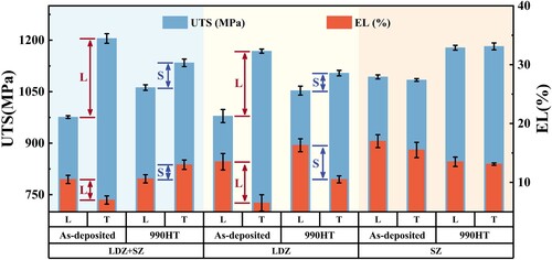
For the LDZ of the as-deposited specimen, it exhibits the same high-strength and low-plasticity properties as other titanium alloys made by additive manufacturing [Citation50–52]. Due to the fine and hard α phases and the continuous αGB phases in the β matrix, they can hinder the movement of the dislocations, making plastic deformation become difficult. Additionally, the high-volume fraction of α phase with a large aspect ratio can lead to an increased stress concentration at the α/β interface during the tensile process, which results in plastic instability. Therefore, for loading along the deposition direction (as-deposited D-L sample), the cracks need to be transferred across the columnar grains boundaries to expand, thereby improving the ductility. However, when loading perpendicular to the deposition direction (as-deposited D-T sample), the continuous αGB phases are perpendicular to the maximum tensile stress, which has a larger hindering effect on slipping and it is easy to induce rapid crack propagation along the continuous αGB phases, resulting in low plasticity. After 900HT heat treatment, the orientation and size of the original β grains are almost unchanged, while a special bimodal microstructure is obtained, which is composed of coarse αp laths and superfine βtrans matrix. Additionally, the αGB phases gradually appear spheroidization and discontinuity. According to the Hall–Petch effect [Citation53], the coarsening of the αp would lead to a decline in strength, whereas the increase in the αp lath volume fraction and the discontinuous αGB are associated with the increase in plasticity of the 900HT D sample, especially the 900HT D-T sample. As for the SZ, after 900HT, the appeared texture of α phase during hot rolling is maintained while the typical deformed streamlined structure into the conventional bimodal microstructure with equiaxed αp and fine lamella α. The equiaxed αp grains play a coordinating role in the deformation and the lamella α phases are beneficial to increase the number of phase interfaces and thus improving the strength [Citation54, Citation55]. The combined effect of the two morphological structures makes the 900HT S sample have an excellent strength and plasticity matching.
4.2. Deformation and fracture mechanism of the 990HT D + S sample
From the above results, there is a gradient microstructure from the top LDZ to the bottom SZ of the 990HT D + S sample (). It is widely accepted that the microstructure determines the mechanical properties, thus the heterogeneous 990HT D + S sample can behave a special deformation behaviour which is preliminarily observed in the DIC test and it is different from the homogeneous structure in the tensile deformation process. (a) shows that there is a significant strength mismatch between the LDZ and SZ of the 990HT D + S specimen. This indicates that when the tensile stress is increased to the yield strength of the LDZ, the LDZ begins to yield and undergo plastic deformation. Consequently, the strain observed in the 990HT D + S sample during the tensile test is mainly attributed to this zone because the tensile stress has not reached yield strength of the SZ. Further support for this conclusion can be obtained from the test results of DIC. (b) presents the displacement-time curves of the selected points in the tensile gauge length of the 990HT D + S sample. One point is chosen as a datum point on the bottom of the gauge length and the displacement of different points can be measured by lit = |yit - y0|, where lit is the displacement of point i at moment t. Clearly, the plastic deformation is mainly concentrated in the LDZ, yet the plastic deformation in the SZ can be neglected. Finally, the tortuous transgranular ductile fracture occurs in the LDZ as shown in the (a).
Figure 14. (a) The schematic illustration of the mismatch strength in the 990HT D + S-L sample. (b) The displacement-time curves of the selected points during DIC test in the tensile gauge length of the 990HT D + S-L sample.
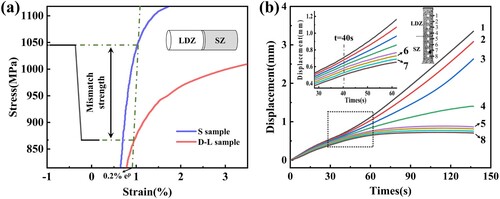
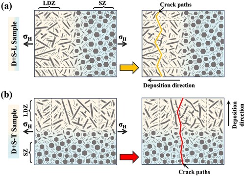
Figure 15. The crack propagation diagrams of the 990HT (a) D + S-L and (b) D + S-T samples.
It’s reported that the plastic deformation behaviour of α phases is a key factor affecting the yield strength of titanium alloys with a high content of α phases [Citation56]. Moreover, the plastic deformation ability can be characterised by Schmid factor (m), which is the ratio of the critical resolved shear stress (CRSS) to the maximum contact pressure [Citation57]. It serves as an important parameter to evaluate the activity of the slip system. And the larger the Schmid factor, the larger the resolved shear stresses will be and the more easily the slip system can be activated. The main slip systems of α phase with HCP structure are basal slip system ({0001} < 110>), prismatic slip system ({1
00} < 11
0>) and pyramidal slip system ({10
1} < 11
0 > or {10
1} < 11
3>) [Citation58]. Among the three slip systems, the CRSS value of basal slip system and prismatic slip system are almost equal, but all much lower than that of pyramidal slip system. When the loading direction is parallel to the deposition direction, due to the α phase texture variance between the LDZ and SZ, the Schmid factor values for basal slip system and prismatic slip system in the two zones of the 990HT D + S sample are different. Calculated according to the method in the literature [Citation36], the average Schmid factor for basal slip system and pyramidal slip system in the LDZ and SZ are 0.46 and 0.39, respectively. It consists with the in-situ XRD tensile results that the α phases in the LDZ of the 990HT samples are easier to slip than those in the SZ.
As for the 990HT D + S-T sample, when the loading perpendicular to the deposition direction, the LDZ and SZ are all suffer the elastic and plastic deformation. In the elastic deformation stage, similar to the homogeneous material, the strain is uniform and no abnormal phenomenon occurs. However, in the subsequent plastic deformation process, as shown in (b), it can be subdivided into three stages. Based on the loading condition and the rule-of-mixture [Citation59, Citation60], in the stage I, Δσ = [(ELDZ + ESZ)/2]·Δϵ. Additionally, as for stage II, Δσ = [((dσLDZ/dϵLDZ) + ESZ)/2]·Δϵ can be obtained. Therefore, according to the two equations, the strain–stress curve showing strictly linear transition at stage I, and the decreasing slope of the 990HT D + S-T sample curve at stage II can be attributed to the as decreasing dσLDZ/dϵLDZ with increasing strain. This mechanical mismatch between the LDZ and SZ will generate a plastic strain gradient. It has been shown that the strain gradient will be accommodated by geometrically necessary dislocations (GNDs). As presented in , the GNDs densities in the LDZ and SZ of the 990HT D + S-T sample are all higher than those in the 990HT D-T and S samples, respectively. The pile up of GNDs can produce long-range back stress and create the hetero-deformation induced (HDI) hardening strengthening to enhance the ductility [Citation61–64]. This may be the main reason why the 990HT D + S-T sample has the same high ductility as the 990HT S sample. Moreover, combining the fracture morphologies ((g, h)) and DIC results (), the micro-cracks preferentially formed in the LDZ and gradually spread to the SZ, resulting in the final fracture of the 990HT D + S-T sample, as depicted in (b).
Figure 16. The GNDs density mappings at the same position of different tensile fracture samples: (a) the 990HT D-T sample; (b) the 990HT S sample; (c)-(d) the LDZ and SZ of the 990HT D + S-T sample, respectively.
5. Conclusions
In this work, the hybrid manufactured TC11 alloy was prepared and subjected to the sub-critical annealing treatment. The microstructure evolution and corresponding tensile performance of the hybrid manufactured TC11 alloy before and after heat treatment were evaluated. Furthermore, the deformation and fracture mechanism of the heat-treated hybrid manufactured TC11 alloy were studied. The main conclusions are:
The hybrid manufactured TC11 samples including three zones: the LDZ, HAZ and SZ. After sub-critical annealing treatment, the fine basket-weave structures in the LDZ transformed into a special bimodal microstructure contained coarse αp laths and superfine βtrans matrix. The αGB also became discontinuous due to the high solution temperature near βtrans temperature. In the SZ, the microstructure changed from a typical deformed streamlined structure into the conventional bimodal microstructure. As for the HAZ, a gradient microstructure that was accompanied with the gradual changes in the morphology and content of αp phases from top to bottom was formed.
The tensile anisotropy of the hybrid manufactured specimens was substantially reduced. When loading along to the deposition direction, the UTS of the hybrid manufactured sample, the LDZ sample and the SZ sample were all increased. When loading perpendicular to the deposition direction, the ductility of the hybrid manufactured sample and the LDZ sample were also improved. In particular, the EL and RA of the heat-treated hybrid manufactured TC11 specimens can reach 13.0% and 29.0%, increased by 86% and 76%, respectively, which was comparable to that of the SZ sample.
The occurrence of mechanical mismatch phenomena in the heat-treated hybrid manufactured TC11 samples resulted in non-uniform strain distribution during the tensile deformation process. When loading along to the deposition direction, the average Schmid factor for basal slip system and pyramidal slip system in the LDZ and SZ were 0.46 and 0.39, respectively. This consisted with the in-situ XRD tensile and DIC results that the α phases in the LDZ were easier to slip. When loading perpendicular to the deposition direction, mechanical mismatch between the LDZ and SZ may produce long-range back stress and create the HDI hardening strengthening to enhance the ductility.
Disclosure statement
No potential conflict of interest was reported by the author(s).
Data availability statement
The data that support the findings of this study are available from the corresponding author upon reasonable request.
Additional information
Funding
References
- Singh G, Ramamurty U. Boron modified titanium alloys. Prog Mater Sci. 2020;111:100653. doi:10.1016/j.pmatsci.2020.100653
- Banerjee D, Williams JC. Perspectives on titanium science and technology. Acta Mater. 2013;61(3):844–879. doi:10.1016/j.actamat.2012.10.043
- Zhao QY, Sun QY, Xin SW, et al. High-strength titanium alloys for aerospace engineering applications: A review on melting-forging process. Mater Sci Eng, A. 2022;845:143260. doi:10.1016/j.msea.2022.143260
- Sola A, Trinchi A. Boron-induced microstructural manipulation of titanium and titanium alloys in additive manufacturing. Virtual Phys Prototyp. 2023;18(1):e2230467. doi:10.1080/17452759.2023.2230467
- Sui S, Chew Y, Weng F, et al. Achieving grain refinement and ultrahigh yield strength in laser aided additive manufacturing of Ti− 6Al− 4 V alloy by trace Ni addition. Virtual Phys Prototyp. 2021;16(4):417–427. doi:10.1080/17452759.2021.1949091
- Dolev O, Osovski S, Shirizly A. Ti-6Al-4 V hybrid structure mechanical properties—Wrought and additive manufactured powder-bed material. Addit Manuf. 2021;37:101657. doi:10.1016/j.addma.2020.101657
- Kuai ZZ, Li ZH, Liu B, et al. Microstructure and mechanical properties of CuCrZr/316L hybrid components manufactured using selective laser melting. J Alloys Compd. 2023;955:170103. doi:10.1016/j.jallcom.2023.170103
- Zhai W, Wang P, Ng FL, et al. Hybrid manufacturing of γ-TiAl and Ti–6Al–4 V bimetal component with enhanced strength using electron beam melting. Compos Part B: Eng. 2021;207:108587. doi:10.1016/j.compositesb.2020.108587
- Guo BJ, Zhang YS, He F, et al. Origins of the mechanical property heterogeneity in a hybrid additive manufactured Hastelloy X. Mater Sci Eng, A. 2021;823:141716. doi:10.1016/j.msea.2021.141716
- Bandyopadhyay A, Zhang Y, Onuike B. Additive manufacturing of bimetallic structures. Virtual Phys Prototyp. 2022;17(2):256–294. doi:10.1080/17452759.2022.2040738
- Herzog D, Seyda V, Wycisk E, et al. Additive manufacturing of metals. Acta Mater. 2016;117:371–392. doi:10.1016/j.actamat.2016.07.019
- Ma J, Zhang Y, Li J, et al. Microstructure and mechanical properties of forging-additive hybrid manufactured Ti–6Al–4 V alloys. Mater Sci Eng, A. 2021;811:140984. doi:10.1016/j.msea.2021.140984
- Ma HY, Wang J, Qin P, et al. Advances in additively manufactured titanium alloys by powder bed fusion and directed energy deposition: Microstructure, defects, and mechanical behavior. J Mater Sci Technol. 2023;183:32–62. doi:10.1016/j.jmst.2023.11.003
- Zhao D, Guo Y, Lai R, et al. Abnormal three-stage plastic deformation in a 17-4 PH stainless steel fabricated by laser powder bed fusion. Mater Sci Eng, A. 2022;858:144160. doi:10.1016/j.msea.2022.144160
- Liu Z, Zhao D, Wang P, et al. Additive manufacturing of metals: Microstructure evolution and multistage control. J Mater Sci Technol. 2022;100:224–236. doi:10.1016/j.jmst.2021.06.011
- Wu Y, Zhao X, Chen Q, et al. Strengthening and fracture mechanisms of a precipitation hardening high-entropy alloy fabricated by selective laser melting. Virtual Phys Prototyp. 2022;17(3):451–467. doi:10.1080/17452759.2022.2037055
- Wang T, Zhu YY, Zhang SQ, et al. Grain morphology evolution behavior of titanium alloy components during laser melting deposition additive manufacturing. J Alloys Compd. 2015;632:505–513. doi:10.1016/j.jallcom.2015.01.256
- Lu HF, Deng WW, Luo KY, et al. Tailoring microstructure of additively manufactured Ti6Al4 V titanium alloy using hybrid additive manufacturing technology. Addit Manuf. 2023;63:103416. doi:10.1016/j.addma.2023.103416
- Carroll BE, Palmer TA, Beese AM. Anisotropic tensile behavior of Ti–6Al–4 V components fabricated with directed energy deposition additive manufacturing. Acta Mater. 2015;87:309–320. doi:10.1016/j.actamat.2014.12.054
- Chi JX, Cai ZY, Zhang HP, et al. Titanium alloy components fabrication by laser depositing TA15 powders on TC17 forged plate: Microstructure and mechanical properties. Mater Sci Eng, A. 2021;818:141382. doi:10.1016/j.msea.2021.141382
- Bambach M, Sizova I, Sydow B, et al. Hybrid manufacturing of components from Ti-6Al-4 V by metal forming and wire-arc additive manufacturing. J Mater Process Technol. 2020;282:116689. doi:10.1016/j.jmatprotec.2020.116689
- Gao HW, Wang JW, Yang JW, et al. Heterogeneous deformation behavior of hybrid manufactured TC11 titanium alloy via directed energy deposition. Mater Sci Eng, A. 2023;867:144728. doi:10.1016/j.msea.2023.144728
- Lu XF, Lin X, Chiumenti M, et al. Residual stress and distortion of rectangular and S-shaped Ti-6Al-4 V parts by Directed Energy Deposition: Modelling and experimental calibration. Addit Manuf. 2019;26:166–179. doi:10.1016/j.addma.2019.02.001
- Kang N, Lin X, El Mansori M, et al. On the effect of the thermal cycle during the directed energy deposition application to the in-situ production of a Ti-Mo alloy functionally graded structure. Addit Manuf. 2020;31:100911. doi:10.1016/j.addma.2019.100911
- Ling WL, Wang XP, Li Y, et al. In-situ investigation on tensile deformation and fracture behaviors of inhomogeneous microstructure during laser repair of Ti-6Al-4 V titanium alloy. Eng Fract Mech. 2023;291:109538. doi:10.1016/j.engfracmech.2023.109538
- Shen SX, He B, Wang HM. Heterogeneous deformation behavior of hybrid manufactured high strength titanium alloy: Coordinate deformation and stress concentration. Mater Sci Eng. A. 2022;849:143467. doi:10.1016/j.msea.2022.143467
- Sabban R, Bahl S, Chatterjee K, et al. Globularization using heat treatment in additively manufactured Ti-6Al-4 V for high strength and toughness. Acta Mater. 2019;162:239–254. doi:10.1016/j.actamat.2018.09.064
- Vrancken B, Thijs L, Kruth JP, et al. Heat treatment of Ti6Al4 V produced by Selective Laser Melting: Microstructure and mechanical properties. J Alloys Compd. 2012;541:177–185. doi:10.1016/j.jallcom.2012.07.022
- Khorasani AM, Gibson I, Ghasemi A, et al. A comprehensive study on variability of relative density in selective laser melting of Ti-6Al-4 V. Virtual Phys Prototyp. 2019;14(4):349–359. doi:10.1080/17452759.2019.1614198
- Liu D, Wu D, Ma G, et al. Effect of post-deposition heat treatment on laser-TIG hybrid additive manufactured Al-Cu alloy. Virtual Phys Prototyp. 2020;15(4):445–459. doi:10.1080/17452759.2020.1818021
- Yan XC, Yin S, Chen CY, et al. Effect of heat treatment on the phase transformation and mechanical properties of Ti6Al4 V fabricated by selective laser melting. J Alloys Compd. 2018;764:1056–1071. doi:10.1016/j.jallcom.2018.06.076
- Liang ZL, Sun ZG, Zhang WS, et al. The effect of heat treatment on microstructure evolution and tensile properties of selective laser melted Ti6Al4 V alloy. J Alloys Compd. 2019;782:1041–1048. doi:10.1016/j.jallcom.2018.12.051
- Lu Y, Tang H, Fang Y, et al. Microstructure evolution of sub-critical annealed laser deposited Ti–6Al–4 V alloy. Mater Des. 2012;37:56–63. doi:10.1016/j.matdes.2011.12.016
- Zhao Z, Chen J, Tan H, et al. Achieving superior ductility for laser solid formed extra low interstitial Ti-6Al-4 V titanium alloy through equiaxial alpha microstructure. Scr Mater. 2018;146:187–191. doi:10.1016/j.scriptamat.2017.11.021
- Zhang G, Li N, Gao J, et al. Wire-fed electron beam directed energy deposition of Ti–6Al–2Zr–1Mo–1 V alloy and the effect of annealing on the microstructure: texture, and anisotropy of tensile properties. Addit Manuf. 2022;49:102511. doi:10.1016/j.addma.2021.102511
- Li RK, Wang HM, Zheng DD, et al. Texture evolution during sub-critical annealing and its effect on yield strength anisotropy of laser directed energy deposited Ti-6Al-2Zr-1Mo-1 V alloy. Mater Sci Eng, A. 2022;850:143556. doi:10.1016/j.msea.2022.143556
- Kamath RR, Nandwana P, Ren Y, et al. Solidification texture,: variant selection, and phase fraction in a spot-melt electron-beam powder bed fusion processed Ti-6Al-4 V. Addit Manuf. 2021;46:102136. doi:10.1016/j.addma.2021.102136
- Wang WK, Chen WZ, Zhang WC, et al. Effect of deformation temperature on texture and mechanical properties of ZK60 magnesium alloy sheet rolled by multi-pass lowered-temperature rolling. Mater Sci Eng, A. 2018;712:608–615. doi:10.1016/j.msea.2017.12.024
- Ter Haar GM, Becker TH. The influence of microstructural texture and prior beta grain recrystallisation on the deformation behaviour of laser powder bed fusion produced Ti–6Al–4 V. Mater Sci Eng, A. 2021;814:141185. doi:10.1016/j.msea.2021.141185
- Zou Z, Simonelli M, Katrib J, et al. Microstructure and tensile properties of additive manufactured Ti-6Al-4 V with refined prior-β grain structure obtained by rapid heat treatment. Mater Sci Eng, A. 2021;814:141271. doi:10.1016/j.msea.2021.141271
- Sofinowski K, Smíd M, Kubena I, et al. In situ characterization of a high work hardening Ti-6Al-4 V prepared by electron beam melting. Acta Mater. 2019;179:224–236. doi:10.1016/j.actamat.2019.08.037
- Kang J, Oh HS, Wei S, et al. An in situ study of microstructural strain localization and damage evolution in an (α+ β) Ti-Al-V-Fe-Si-O alloy. Acta Mater. 2023;242:118424. doi:10.1016/j.actamat.2022.118424
- Warwick JLW, Jones NG, Rahman KM, et al. Lattice strain evolution during tensile and compressive loading of CP Ti. Acta Mater. 2012;60(19):6720–6731. doi:10.1016/j.actamat.2012.08.042
- Stapleton AM, Raghunathan SL, Bantounas I, et al. Evolution of lattice strain in Ti–6Al–4 V during tensile loading at room temperature. Acta Mater. 2008;56(20):6186–6196. doi:10.1016/j.actamat.2008.08.030
- Syn C, Lesuer D, Sherby O. Enhancing tensile ductility of a particulate-reinforced aluminum metal matrix composite by lamination with Mg-9% Li alloy. Mater Sci Eng, A. 1996;206(2):201–207. doi:10.1016/j.msea.2021.141271
- Wu Y, Liaw PK, Li R, et al. Relationship between the unique microstructures and behaviors of high-entropy alloys. Int J Miner Metall Mater. 2024;31(6):1350–1363. doi:10.1007/s12613-023-2777-4
- Ren Y-M, Lin X, Fu X, et al. Microstructure and deformation behavior of Ti-6Al-4 V alloy by high-power laser solid forming. Acta Mater. 2017;132:82–95. doi:10.1016/j.actamat.2017.04.026
- Cai C, Wu X, Liu W, et al. Selective laser melting of near-α titanium alloy Ti-6Al-2Zr-1Mo-1V: Parameter optimization, heat treatment and mechanical performance. J Mater Sci Technol. 2020;57:51–64. doi:10.1016/j.jmst.2020.05.004
- Liu Y, Xu L, Qiu C. Development of an additively manufactured metastable beta titanium alloy with a fully equiaxed grain structure and ultrahigh yield strength. Addit. Manuf. 2022;60:103208. doi:10.1016/j.addma.2022.103208
- Zhang XY, Fang G, Leeflang S, et al. Effect of subtransus heat treatment on the microstructure and mechanical properties of additively manufactured Ti-6Al-4 V alloy. J Alloys Compd. 2018;735:1562–1575. doi:10.1016/j.jallcom.2017.11.263
- Fan H, Yang S. Effects of direct aging on near-alpha Ti–6Al–2Sn–4Zr–2Mo (Ti-6242) titanium alloy fabricated by selective laser melting (SLM). Mater Sci Eng, A. 2020;788:139533. doi:10.1016/j.msea.2020.139533
- Zhang F, Wang K, Li Y, et al. Composition fine-tuning for directed energy deposition of Ti-6Al-4 V. J Mater Process Technol. 2022;299:117321. doi:10.1016/j.jmatprotec.2021.117321
- Wang XW, Wang CJ, Liu Y, et al. An energy based modeling for the acoustic softening effect on the Hall-Petch behavior of pure titanium in ultrasonic vibration assisted micro-tension. Int J Plast. 2021;136:102879. doi:10.1016/j.ijplas.2020.102879
- Sun Z, Wu H, Sun Q, et al. Tri-modal microstructure in high temperature toughening and low temperature strengthening treatments of near-β forged TA15 Ti-alloy. Mater Charact. 2016;121:213–221. doi:10.1016/j.matchar.2016.10.010
- Sun Z, Li X, Wu H, et al. Morphology evolution and growth mechanism of the secondary Widmanstatten α phase in the TA15 Ti-alloy. Mater Charact. 2016;118:167–174. doi:10.1016/j.matchar.2016.06.026
- Benmessaoud F, Cheikh M, Velay V, et al. Role of grain size and crystallographic texture on tensile behavior induced by sliding mechanism in Ti-6Al-4 V alloy. Mater Sci Eng, A. 2020;774:138835. doi:10.1016/j.msea.2019.138835
- Yang JJ, Yu HC, Wang ZM, et al. Effect of crystallographic orientation on mechanical anisotropy of selective laser melted Ti-6Al-4 V alloy. Mater Charact. 2017;127:137–145. doi:10.1016/j.matchar.2017.01.014
- Bridier F, Villechaise P, Mendez J. Analysis of the different slip systems activated by tension in a α/β titanium alloy in relation with local crystallographic orientation. Acta Mater. 2005;53(3):555–567. doi:10.1016/j.actamat.2004.09.040
- Wu XL, Jiang P, Chen L, et al. Synergetic strengthening by gradient structure. Mater Res Lett. 2014;2(4):185–191. doi:10.1080/21663831.2014.935821
- Liang Y-J, Liu D, Wang H-M. Microstructure and mechanical behavior of commercial purity Ti/Ti–6Al–2Zr–1Mo–1 V structurally graded material fabricated by laser additive manufacturing. Scr Mater. 2014;74:80–83. doi:10.1016/j.scriptamat.2013.11.002
- Mompiou F, Caillard D, Legros M, et al. In situ TEM observations of reverse dislocation motion upon unloading in tensile-deformed UFG aluminium. Acta Mater. 2012;60(8):3402–3414. doi:10.1016/j.actamat.2012.02.049
- Zhu YT, Ameyama K, Anderson PM, et al. Heterostructured materials: superior properties from hetero-zone interaction. Mater Res Lett. 2021;9(1):1–31. doi:10.1080/21663831.2020.1796836
- Shuai C, Zhao Y, Deng Y, et al. Heterogeneous grain structure in biodegradable Zn prepared via mechanical alloying and laser powder bed fusion for strength-plasticity synergy. Virtual Phys Prototyp. 2024;19(1):e2317780. doi:10.1080/17452759.2024.2317780
- Yu S, Wang P, Li H, et al. Heterogeneous microstructure and mechanical behaviour of Al-8.3 Fe-1.3 V-1.8 Si alloy produced by laser powder bed fusion. Virtual Phys Prototyp. 2023;18(1):e2155197. doi:10.1080/17452759.2022.2155197