
 ?Mathematical formulae have been encoded as MathML and are displayed in this HTML version using MathJax in order to improve their display. Uncheck the box to turn MathJax off. This feature requires Javascript. Click on a formula to zoom.
ABSTRACT
With increasing environmental concerns, the building sector must rethink the selection of building materials not only for structural members but also for connections. Densified wooden nails might become an alternative to metallic fasteners, at least in applications with lower structural requirements. However, their structural behaviour in timber-to-timber connections is not yet systematically studied. This paper presents a series of 90 shear tests to explore the shear capacity and slip modulus of timber-to-timber connections with wooden nails. Specimens with different nail dimensions, different nail orientations, and different nail arrangements were investigated. A typical three-member push-out test setup was adopted where the wooden nails were oriented perpendicular or inclined to the shear plane. Specimens with inclined nails exposed to shear and tensile forces showed a higher shear resistance due to the activated tensile capacity of the wooden nails. Failure of the wooden nails was predominantly observed when the nails were loaded in tension. This means that the interface between the wooden nails and the timber did not fail. Based on the results from the shear tests, an analytical model was developed to predict the load bearing capacity of timber-to-timber connections exposed to bending stresses. The analytical model was validated with experimental investigations.
1. Introduction
The building sector is one of the main contributors to material usage and energy consumption (European Commission Citation2014). Due to the increasing environmental concerns, more considerations about sustainability are required in the selection of building materials (Hill and Dibdiakova Citation2016, Niu et al. Citation2021), which also includes connections (Thomson et al. Citation2010). Nails are one of the most widely used connectors in timber structures and they are commonly fabricated from materials with a high environmental impact, mainly steel. Natural materials, such as wood, might become an alternative to metallic fasteners, at least in applications with low structural requirements.
The concept of wooden nail connectors is not new. In ancient times, treenails, or so-called trunnels, which followed a similar concept were widely applied in building structures (Nelson Citation1996) and ship manufacturing (Curtis Citation1918). Treenails are commonly made from hardwood, work as tenons, which are hammered into small-sized, pre-drilled holes in the connecting mortises to create tight joints. The connection can be further strengthened by wood swelling. Compared to metallic nails, wooden nails offer several advantages, such as resistance against corrosion, the ease of disassembly and recycling, as well as the smaller self-weight.
Wood densification improves the mechanical properties (Blomberg Citation2006), and is accordingly used in manufacturing wooden dowels, where a considerable laterally loaded capacity was recognised (Jung et al. Citation2008, Conway et al. Citation2021). It allows a further development of sustainable timber structures, such as adhesive free timber joints (El-Houjeyri et al. Citation2019, Bouhala et al. Citation2020), and dowel laminated timber (Sotayo et al. Citation2020).
During the last years, several research projects were conducted to investigate the applications of densified wood in nails. Inoue et al. (Citation2010) investigated the bending property of wooden-based nails made from compressed Madake bamboo (Phyllostachys bambusoides) and Japanese cedar (Cryptomeria japonica) for an application in wooden pallets. Riggio et al. (Citation2016) investigated the compressive strength and the shear resistance of densified wooden nails made from European beech (F. sylvatica L.), European aspen (P. tremula L.), European ash (F. excelsior L.) and black locust (R. pseudoacacia L.). The results showed that a moderate load bearing capacity of wooden nail connections exposed to pure compressive or shear stresses could be identified. Lademann (Citation2018a, Citation2018b) reported the mechanical properties of densified beech wood nails, such as yield moment, tensile capacity, and shear resistance.
Due to the structural and environmental potential, densified wooden nails are becoming more popular in timber constructions. For example, the Buga Wood Pavilion in Germany (Alvarez et al. Citation2019) employed densified wooden nails to connect LVL boards and plywood panels in the cassette (modular) assembly. As proposed by Hasan et al. (Citation2019), densified wooden nails may be used in a robotic fabrication process of nailed laminated timber. Furthermore, an application of densified wooden nails was proposed in a wooden trail design project (Fink et al. Citation2019, Ruan et al. Citation2021), in which a concept of nail laminated timber deck system assembled with short-length salvaged timber boards was performed. In such application, the external loads were mainly carried by the shear resistance of wooden nail connections.
The present research project was motivated by the afore-mentioned design concept proposed by Fink et al. (Citation2019), where short, salvaged timber boards were connected with wooden nails. For the load transfer, nails are exposed to shear loads and the entire connections are supposed to resist bending stresses. The experimental investigations in the present study are based on the loading scenario from the design concept and focuses on the shear capacity of timber-to-timber connections using densified wooden nails. Wooden nail connections with different nail dimensions, different nail orientations and different nail arrangements were experimentally tested. Based on the results, one nail arrangement was selected and applied for an explorative investigation of the structural potential of wooden nail connections exposed to bending stresses. An analytical model to predict the load-bearing capacity of the connections was developed, and a series of bending tests were carried out to validate the model.
2. Materials and method
The shear capacity of timber-to-timber connection using wooden nails was experimentally investigated using a symmetrical, three-member configuration (see ). In line with the practical use, such as the proposal by Fink et al. (Citation2019), the timber boards were arranged perpendicular to the loading direction in the experimental investigations. In total 90 shear tests with varying parameters, including three different types of nails and seven different nail arrangements, were performed. The specimens were grouped into 18 series, and each series contained five specimens. An overview of the experimental tests is presented in .
Figure 1. Test setup for the shear tests.
Note: The numbers indicate the position of the LVDTs.
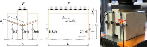
Table 1. Design parameters of the specimens in shear tests.
2.1. Materials
The specimens were fabricated from graded timber boards (l × t × w = 5400 × 48 × 123 mm3, strength grade C24 according to EN Citation338 (Citation2016)). The timber boards were stored in a climate room at a temperature of 20°C and a relative humidity of 65% before cutting, assembly and testing. The moisture content of timber boards was between 9% and 13%, measured with an electric resistance device (Protimeter Timbermaster®).
The timber boards were connected with wooden nail fasteners (Lignoloc®) made from compressed European beech (F. sylvatica L.). Three different nail dimensions were investigated. The dimensions and selected mechanical properties of the wooden nails are presented in . For a detailed description, it is referred to the technical reports of the wooden nail products (Lademann Citation2018a, Citation2018b).
2.2. Specimens
The shear tests were performed on symmetrical three-member specimens (see and ). A vertical offset sv = 15 mm of the middle member was chosen in order to ensure a failure of the fastener during the shear test. The wood nails were placed in the centre of the contact surface hm ≈ 70 mm. A shift between fasteners sh = 10 mm was selected to avoid the possible collision of fasteners. The distances between fasteners and the edges distance followed the minimal spacings required in EN Citation1995-Citation1-Citation1 (Citation2014).
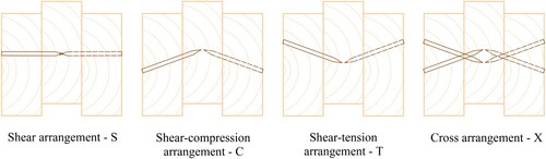
Four different arrangements of the wooden nails, with respect to the resulting forces in the wood nail, were tested, as shown in . Here the nail orientation α is defined as the angle between the axial direction of wooden nail and the direction perpendicular to the shear plane:
Shear arrangement (denoted S): one nail per shear plane, α = 0°.
Shear-compression arrangement (denoted C): one nail per shear plane, α = 15° and 30°.
Shear-tension arrangement (denoted T): one nail per shear plane, α = 15° and 30°.
Cross arrangement (denoted X): two nails per shear plane, α = 15° and 30°.
Figure 2. Definition of the nail arrangements.
The assembly of the specimens was performed with a six-bar air pressure coin nailer (Fasco®). One benefit of using a pneumatic nailer is that it can create high-speed rotations on wooden nails during the nailing process. The friction produced by the rotation generates a certain amount of heat, and melt the surfaces of wood, mainly lignin (Pizzi et al. Citation2004). The melted contact surfaces then get naturally glued after the temperature drops, thus further strengthen the connection (Pizzi et al. Citation2004). An angle reader and a spirit level were installed on the pneumatic nailer to guarantee the accuracy of specific nail orientations during the assembly process.
The present study is limited to the nailing angles to a maximum of α = 30°, even if larger angles might become more efficient from a purely mechanical perspective. However, for the given dimensions of the timber boards and nails, the nailing angle was limited to guarantee enough penetration length and minimal adequate edge distances. Furthermore, the fabrication of nailing angles more than 30° caused additional challenges regarding fabrication, such as the difficulties of nailing the exact angle by manually using the nailer. During the fabrication process, on some nails, damages occurred when nailing through wood-knots or in the area around them. For practical applications, this aspect has to be considered, however, the present specimens were cut in a way that the presence of knots and knot clusters was avoided.
As the present study mainly focuses on the influence of wooden nails (dimensions, orientations and arrangements) on the shear capacity of the connections, the properties of the timber boards, such as the orientation of the timber boards, the distances to pith or wane, were not considered. It might influence the data from the experimental tests.
The wooden nails were inserted from the outside located boards as shown in . However, in a series of pre-tests (25 specimens, see Fink et al. (Citation2019)) a non-symmetric nail arrangement where all nails were inserted from the same side was chosen. A comparison of the effect of the two different nailing approaches on the load-bearing capacity showed deviations less than 5%.
The density of the individual specimens was identified after nailing, by measuring the total weight and dimensions. The specimens were stored in the climate room. The weight of the wood nails was subtracted. The mean value of the density was 468 kg/m3 with COV = 0.06.
2.3. Testing procedure
A force-controlled loading procedure according to EN 26891 (Citation1992) was used. A universal testing machine (UTM) with a maximum compressive force of 200 kN was applied to realise the loading process. The testing procedure requires an estimated value of maximum load Fest for each testing series which should fulfil the requirement in Equation (1), where Fmax is the average maximum load obtained from test results. To guarantee the fulfilment, one preliminary test was conducted first in each series. The obtained maximum load from the preliminary test was used as the estimated maximum load in the tests which were recorded and analysed in this paper.
(1)
(1) On all three timber boards, two linear variable differential transformer (LVDT) transducers were symmetrically arranged in the centre of the specimen (at the height of hL), to measure the displacement. To be noticed, on 13 specimens (in three test series), error measurements in the LVDTs occurred. For those specimens, the stiffness was estimated based on the measurements from the loading device (machine way), using the mean difference between the LVDTs and machine way observed from the other specimens. The corresponding series are marked when presenting the test results. The experimental investigations were carried out at the structural laboratory of Department of Civil Engineering at Aalto University.
3. Results
3.1. Deformation and failure behaviour
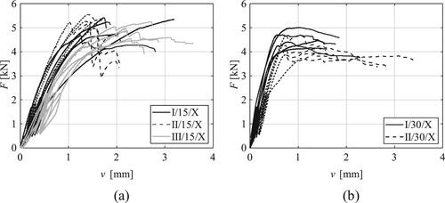
The load-slip curves of the specimens with single nail per shear plane are exemplarily illustrated for type I nails in (a similar behaviour was observed for specimens using type II and type III nails). The load-slip curves for specimens with the cross arrangements (X-specimens) are illustrated in . For all the specimens with the shear arrangements (S-specimens) and with the shear-compression arrangements (C-specimens), a similar load-slip behaviour was obtained. The plastic behaviour resulted from embedment of the wooden nails in the timber boards during the loading process. For the specimens with the shear-tension arrangements (T-specimens), the nails were mainly loaded in tension, and accordingly less embedment occurred. For the 30/T-specimens, a relatively long plateau was observed after the initial loading phase. One possible reason for the plateau is that in the initial phase, the load was mainly transferred by one nail, resulting from asymmetry. The X-specimens were characterised by an initial stiffness, that was dependent on the nailing angles. For the 30/X-specimens, a plastic phase similar with the single nails was observed.
Figure 3. Load-slip curves of the specimens using a pair of type I nails with insertion angles of (a) 0°, (b) 15° and (c) 30°.
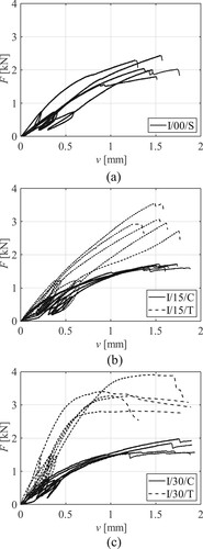
Figure 4. Load-slip curves of the specimens with the cross arrangements nails with insertion angles of (a) 15° and (b) 30°.
Three different types of failure modes were observed in the shear tests, namely failure mode A, B and C (see ). To be noted that, some specimens failed only in one shear plane, possibly resulting from the asymmetrical loading caused by differences in the nail orientation or curved timber boards. One example of a none-failed nail is illustrated in (f). The percentage of the individual failure modes for each group is summarised in .
Figure 5. Fracture pattern of the wood nails: (a-c) failure mode A for different nail arrangements, (d) failure mode B, (e) failure mode C, and (f) no failure of the wooden nail.
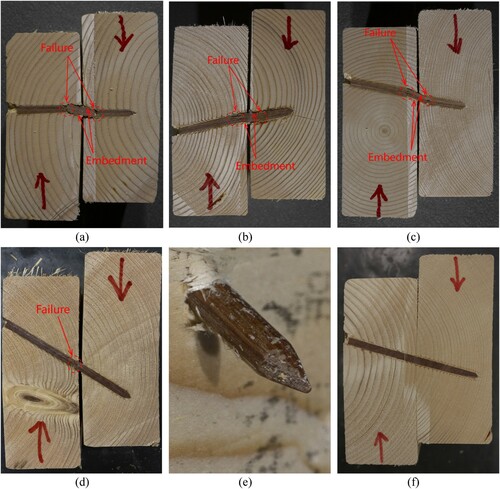
Table 2. Test results of shear tests.
Failure mode A:
The wooden nail broke at two points that were arranged approximately symmetrical about the shear plane. Between the breaking points, embedment was seen in the area where the timber boards were compressed by the wooden nail. On the opposite side of the wooden nail, the bonding surfaces between the nail and the timber boards failed. The outer parts of the wooden nail remained unaffected. Examples of typical failure modes are illustrated in (a–c). The failure mode has similarities with the one for screws (see e.g. Bejtka and Blass Citation2002), but since for wooden nails, no yielding of the fastener can be achieved, here brittle failures occurred after a certain bending of the wooden nails was reached. Failure mode A was observed in all the S- and C-specimens. The failure mode was also observed in some T-specimens with high relevance for nails with small inclinations.
Failure mode B:
The wooden nail broke at one single point (close to the shear plane), due to exceeding its tensile capacity. Only marginal embedment of the wooden nail into the timber boards was observed. Failure mode B appeared only in specimens where the wooden nails were exposed to tensile stresses. An example of a typical failure is illustrated in (d).
Failure mode C:
In this failure mode, the wooden nail was pulled out from the timber board without any visible fracture of the wooden nail ((e)). In all specimens with failure mode C, the nail was pulled out from the middle board, due to the shorter contact length compared to the side boards. Failure mode C was only obtained in the series with 30/T-arranged nails.
3.2. Shear capacity
Shear capacity Fs was defined as the maximum load observed during the test. Overall, the variations of shear capacity within the individual groups were rather small, on average about 10%. The results of shear tests are summarised in and (a).
Figure 6. Test results of (a) shear capacity and (b) slip modulus of wooden nail connections obtained from the shear tests.
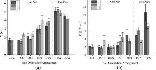
As expected, T-specimens showed a significant higher shear capacity than other specimens, whereas only marginal differences between the other groups were observed. For the 15/T-specimens, the shear capacity was 43% higher for type I, 65% higher for type II and 67% higher for type III nails compared to the S-specimens. For the 30/T-specimens, the differences were even larger: 58% higher for type I and 117% higher for type II nails compared to the S-specimens. The significant difference in type II nails may result from the asymmetrical loading (e.g. in series II/30/T four out of five specimens failed only in one side) which fully activates the tensile capacity of the single nail in one shear plane. An evidence is shown by comparing the obtained shear capacity (Fs = 3.88 kN) and the tensile capacity of the wooden nail (Ft,k = 3.87 kN) (see also ).
No significant influence of nail length on the shear capacity was recognised. It means that the results from specimens fabricated with type I and type II were similar. For the T-specimens, this indicates that the selected minimal insertion length (19.6 mm) was sufficient to transfer the tensile forces in the nail-wood interface. It should be noted that for the nails with a length of 90 mm (insertion length = 34.6 mm), no failure mode C was observed. For the nails with a length of 75 mm (insertion length = 19.6 mm), failure mode C appeared in a few 30/T-specimens, where the corresponding insertion length was small. The specimens with type III nails had a higher shear capacity than the specimens with type I nails, resulting from the higher shear or tensile resistance of type III nails. On average, the shear capacity was about 30% higher.
The shear strength of the X-arranged nails was obviously higher compared to single nails. For the 15/X-specimens, the shear strength was even slightly higher than the sum of the two single nails observed in the tests (series T and C). However, for the 30/X-specimens, the shear strength was lower than the 15/X-specimens, even the T-arranged nails with a larger inclination performed better. One possible reason for the lower shear strength is the significant differences of the slip modulus between the C-arranged and T-arranged nails in the cross pair. Accordingly, the C-arranged nails cannot be fully utilised. In addition, no significant influence of nail length was observed in the X-arranged nails.
For the individual test samples, the influence of the density on the shear strength was investigated. Overall, no correlation was identified which indicates that the shear strength is mainly influenced by the characteristics of wooden nails.
3.3. Slip modulus
The slip modulus Ks was determined by Equation (2) proposed in EN 26891 (Citation1992), where v01 is the slip equivalent to load 0.1Fs,est and v04 is the slip equivalent to load 0.4Fs,est. As the plastic deformations already occurred in the range of v01 to v04 in many specimens, resulting a non-linear behaviour, the variations of slip modulus were relatively large, on average about 23%. It has to be considered that for the specimen preparation only marginal attention was given on the selection of the timber boards, in terms of geometrical desorption, such as wane. This combined with the natural variability of the stiffness properties within timber (see e.g. Fink and Kohler Citation2011), might affect the results, especially for large stiffnesses. The results of slip modulus are summarised in and (b).
(2)
(2) The T-specimens showed a significant higher slip modulus, while only marginal differences were observed between the other groups (S and C). For the 15/T-specimens, the slip modulus was 27% higher for type I, 90% higher for type II and 118% higher for type III nails compared to the S-specimens. For the 30/T-specimens, the differences were even larger: 150% for type I and 100% for type II nails compared to the S-specimens.
No influence of nail length was observed by comparing the specimens fabricated with type I and II nails. The specimens with type III nails showed a higher slip modulus than the specimens with other types of nails in all groups. Comparing the specimens fabricated with type III nails to those with type I nails, on average about 56% higher slip modulus was acquired.
For the X-specimens, a higher slip modulus was observed in the 30/X-arrangements than the 15/X-arrangements. In the 15/X-arrangements, a similar value was obtained for all nails. In the 30/X-arrangements, a higher level of slip modulus was performed in the specimens fabricated with type I nails than those with type II nails. The reasons for the significant differences are not clear but might be related to the sample selection explained above.
4. Timber-to-timber under bending exposure
To predict the bending resistance and to optimise the nail arrangement for the trail, an analytical model was developed and validated with experimental investigations. The investigation was limited to one specific nail arrangement, namely I/15/X. The selection of the nail arrangement resulted from specific production and mechanical reasons, such as comparable high shear resistance, or the smaller required nail spacing compared to the nails with a larger diameter.
4.1. Analytical model
By linking the shear capacity of individual fastener to the overall moment resistance of the connection with multiple fasteners, such as the multi-fastener moment-resisting joint model proposed by Chui and Li (Citation2005), an analytical model to predict the moment resistance of jointed beams connected with wooden nails was developed. In the model, each nail pair was simplified as a point connection in each contact surface represented by the dots in (a). It was assumed that the individual point connections rotate around the geometric centre of the entire connection, and the entire connection fails when the furthest nails (regarding the geometric centre) reach the maximum load (Fs). The contribution of each nail pair to the overall moment resistance was assumed as linearly affected by the distance between each nail pair and rotational centre (denoted di), following the linear load-slip behaviours from the tests. Based on the results from the shear tests, a comparably low load level was expected. Accordingly, bending in the timber boards was neglected. Furthermore, friction between the timber boards was assumed to be small and was therefore neglected. The predicted moment resistance provided by the wooden nails was calculated according to Equation (3), where Fs,i is the shear capacity of the wooden nail pairs.
(3)
(3)
Figure 7. Bending tests: (a) definition of nail spacing and schematics for the analytical model, and (b) test setup.
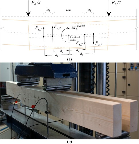
4.2. Experimental investigation
Four-point bending tests with a span l = 1200 mm were performed. A symmetrical arrangement (three timber boards with two shear planes) was chosen, in order to avoid torsion (see (b)). In total 18 specimens were tested. Half of the specimens were connected with 8 nails (two cross-arranged nail pairs per shear plane) and the other half with 16 nails (four cross-arranged nail pairs per shear plane). For both groups, three different geometrical arrangements were tested (see for a compilation of the dimensions).
Table 3. Number of specimens, geometric parameters of the specimens and test results of bending tests.
The test setup is illustrated in . Below each loading point, two LVDTs were placed, one on each side of the specimen to measure the vertical displacement. For the specimens with an overlapping length larger than 400 mm (distance between the loading points), the LVDTs were placed 200 mm outside the loading points as the inner timber member was covered by outer members at the loading points. Steel plates were placed at the loading points and at the supports to reduce local stress concentrations and deformations of the timber boards. The bending tests were performed on the UTM described in Section 2.3. The estimated maximum force in each of the series was defined by a preliminary test and checked with Equation (1) after the completion of the formal tests.
4.3. Test results and comparison to analytical model
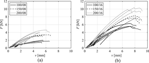
The load-deformation curves are presented in . For all specimens, a rather constant increase of the plastic deformation, resulting from the embedment, was observed. One of the curves either in series 200/08 (see (a)) or series 150/16 (see (b)) showed a significantly smaller stiffness. The specimens were characterised by twisted timber boards which resulted in a larger initial displacement. Nevertheless, the influence of the initial displacement on the load bearing capacity is neglectable.
Figure 8. Load-deformation curves of bending specimens by using (a) 8 nails and (b) 16 nails.
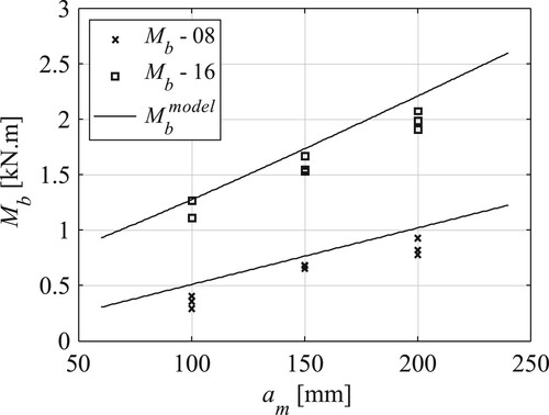
The moment resistance of timber-to-timber connections exposed to bending moments Mb was determined by Equation (4), where Fb is the maximum load obtained from the bending tests and lb represents the span of the specimen.
(4)
(4) The comparison between the predictions based on the analytical model and the results of bending tests are illustrated in . Overall, a wide agreement was observed for both specimens using eight and 16 nails. However, the predicted values were slightly larger than the test results. The over-estimation was similar for all specimens, ranged in 0.07–0.24 kN·m. A possible reason was that a part of moment resistance got lost because of the extra rotational and horizontal loads on wooden nails which were neglected in the analytical model.
Figure 9. Comparison of predicted moment resistance of the jointed beams and the test results obtained from the bending tests.
5. Conclusions
In this paper, the mechanical behaviour of timber-to-timber connections using densified wooden nails was investigated. Based on 90 shear tests with various nail arrangements, the load-bearing capacity, the load-slip behaviour, and the failure modulus were investigated and described.
Specimens connected with single nail per shear plane oriented perpendicular to the shear plane were characterised by similar mechanical properties with specimens connected with inclined nails resulting in additional compressive stresses. For all these specimens, the same failure mode of the wooden nails was observed, as the wooden nails broke at two points that were arranged approximately symmetrical about the shear plane. In contrast, specimens connected with inclined nails orientated in the opposite direction (resulting additional tensile stresses) showed a higher load-bearing capacity and a higher slip modulus. Here a positive trend at increasing nailing angles was observed. For specimens with the nails resulting additional tensile stresses, failure modes typical for tensile loaded fasteners were observed: tensile failure of the wooden nails and pull-out failure.
The pull-out failures were mainly observed for short nails at a large nailing angle, which resulted in high tensile stresses combined with short force transmission length. However, the shear strength for both failure modes was similar, indicating that the insertion length was sufficient to transfer the tensile forces of the wood-nail interface.
Specimens connected with the cross-arranged nails at a small nailing angle showed a higher shear strength than specimens with the cross-arranged nails at a large nailing angle, even though the specimens connected with the single nails at a large nailing angle had a better performance than specimens with the single nails at a small nailing angle. This might be explained by the significant difference of the slip modulus for the two nails in the cross pair, especially at a large nailing angle. Accordingly, the load-carrying capacity of the nails resulting additional compressive stresses could not be fully activated.
The experimental investigations were limited to five different nailing angles up to α = 30°. However, from a purely mechanical perspective, nailing at larger angles might become more efficient. Further investigations are required to find the optimal nailing angle.
An analytical model to estimate the load-bearing capacity of wooden nail connections exposed to bending stresses was developed. The model was based on the results from the performed shear tests. For the model validation, 18 bending tests with six different geometrical arrangements were performed. A good match of the predictions from the analytical model and the test results was obtained. The mechanical model will be used to optimise the nailing strategy for the design of plate elements from salvaged timber boards.
Inspired by the findings in the study, structural potentials of wooden nail connections can be distinguished when wooden nails are mainly loaded in tension. Further research will focus on the exploration of proper structural forms, such as planar or curved forms, to fully utilise the structural potentials of wooden nail connections.
Acknowledgements
The authors would like to thank Stefan Siemers and Beck Fastener Group for providing the wooden nails and the pneumatic nailing device.
Disclosure statement
No potential conflict of interest was reported by the author(s).
References
- Alvarez, M., Wagner, H. J., Groenewolt, A., Krieg, O. D., Kyjanek, O., Sonntag, D., Bechert, S., Aldinger, L., Menges, A. and Knippers, J. (2019) The Buga Wood Pavilion - integrative interdisciplinary advancements of digital timber architecture. In 39th ACADIA Conference 2019, Austin, USA.
- Bejtka, I. and Blass, H. J. (2002) Joints with inclined screws. In Proceedings of meeting 35 of the working commission W18 – timber structures, CIB. Kyoto, Japan.
- Blomberg, J. (2006) Mechanical and physical properties of semi-isostatically densified wood (Doctoral dissertation, Luleå tekniska universitet).
- Bouhala, L., Fiorelli, D., Makradi, A., Belouettar, S., Sotayo, A., Bradley, D. F. and Guan, Z. (2020) Advanced numerical investigation on adhesive free timber structures. Composite Structures, 246, 112389.
- Chui, Y. H. and Li, Y. (2005) Modeling timber moment connection under reversed cyclic loading. Journal of Structural Engineering, 131, 1757–1763.
- Conway, M., Mehra, S., Harte, A. M. and O’Ceallaigh, C.. (2021) Densified wood dowel reinforcement of timber perpendicular to the grain: A pilot study. Journal of Structural Integrity and Maintenance, 6(3), 177–186.
- Curtis, W. H. (1918) The Elements of Wood Ship Construction (Philadelphia: Shipping Board, Emergency Fleet Corporation).
- El-Houjeyri, I., Thi, V-D., Oudjene, M., Khelifa, M., Rogaume, Y., Sotayo, A. and Guan, Z. (2019) Experimental investigations on adhesive free laminated oak timber beams and timber-to-timber joints assembled using thermo-mechanically compressed wood dowels. Construction and Building Materials, 222, 288–299.
- EN 1995-1-1 (2014) Eurocode 5: Design of Timber Structures – Part 1-1: General – Common Rules and Rules for Buildings (Brussels: European committee for standardization).
- EN 26891 (1992) Timber Structures – Joints Made with Mechanical Fasteners. General Principles for the Determination of Strength and Deformation Characteristics (Brussels: European committee for standardization).
- EN 338 (2016) Structural Timber – Strength Classes (Brussels: European committee for standardization).
- European Commission (2014) Energy Efficient Buildings. Accessed 22 March 2021, available at: https://ec.europa.eu/energy/en/topics/energy-efficiency/buildings.
- Fink, G. and Kohler, J. (2011) Multiscale variability of stiffness properties of timber boards. In ICASP Applications of Statistics and Probability in Civil Engineering, Zurich, Switzerland.
- Fink, G., Ruan, G. and Filz, G. H. (2019) Sustainable design concepts for short span, timber-only structures. In Proceedings of IASS Annual Symposium 2019 – Structural Membranes 2019: Form and Force, Barcelona, Spain.
- Hasan, H., Reddy, A. and Tsayjacobs, A. (2019) Robotic fabrication of nail laminated timber. In Proceedings of the 36th ISARC, Banff, Canada.
- Hill, C. A. S. and Dibdiakova, J. (2016) The environmental impact of wood compared to other building materials. International Wood Products Journal, 7(4), 215–219.
- Inoue, M., Adachi K., Kamachi, K. and Yokoi, M. (2010) Development of wooden-based nails for wooden pallet. In Proceedings of the International Convention of Society of Wood Science and Technology and United Nations Economic Commission for Europe - Timber Committee, Geneva, Switzerland.
- Jung, K., Kitamori, A. and Komatsu, K. (2008) Evaluation on structural performance of compressed wood as shear dowel. Holzforschung, 62, 461–467.
- Lademann, O. (2018a) Report: Mechanical properties of LIGNOLOC® wooden nails – 4,7mm. Accessed 17 March 2021, available at: https://www.beck-lignoloc.com/fileadmin/user_upload/LignoLoc_VHT_Bericht_4_7mm_EN.PDF.
- Lademann, O. (2018b) Report: Mechanical properties of LIGNOLOC® wooden nails – 5,3mm. Accessed 17 March 2021, available at: https://www.beck-lignoloc.com/fileadmin/user_upload/LignoLoc_VHT_Bericht_5_3mm_EN.PDF.
- Nelson, L. H. (1996) Early wooden truss connections vs. wood shrinkage: From mortise-and-tenon joints to bolted connections. APT Bulletin: The Journal of Preservation Technology, 27(1/2), 11–23.
- Niu, Y., Rasi, K., Hughes, M., Halme, M. and Fink, G. (2021) Prolonging life cycles of construction materials and combating climate change by cascading: The case of reusing timber in Finland. Resources, Conservation & Recycling, 170, 105555.
- Pizzi, A., Leban, J.-M., Kanazawa, F., Properzi, M. and Pichelin, F. (2004) Wood dowel bonding by high-speed rotation welding. Journal of Adhesion Science and Technology, 18(11), 1263–1278.
- Riggio, M., Sandak, J. and Sandak, A. (2016) Densified wooden nails for new timber assemblies and restoration works: A pilot research. Construction and Building Materials, 102, 1084–1092.
- Ruan, G., Filz, G. H. and Fink, G. (2021) An integrated architectural and structural design concept by using local, salvaged timber. In Proceedings of IASS Annual Symposium 2020/21 and the 7th International Conference on Spatial Structure: Inspiring the Next Generation, Guilford, UK. (Accepted for publication)
- Sotayo, A., Bradley, D., Bather, M., Sareh, P., Oudjene, M., El-Houjeyri, I., Harte, A. M., Mehra, S., O'Ceallaigh, C., Haller, P., Namari, S., Makradi, A., Belouettar, S., Bouhala, L., Deneufbourg, F. and Guan, Z. (2020) Review of state of the art of dowel laminated timber members and densified wood material as sustainable engineered wood products for construction and building applications. Developments in the Built Environment, 1, 100004.
- Thomson, A., Harris, R., Ansell, M. and Walker, P. (2010) Experimental performance of non-metallic mechanically fastened timber connections. The Structural Engineer, 88(17), 25–32.