
 ?Mathematical formulae have been encoded as MathML and are displayed in this HTML version using MathJax in order to improve their display. Uncheck the box to turn MathJax off. This feature requires Javascript. Click on a formula to zoom.
ABSTRACT
In this study, the effect of dimethyl ether enriched air (DMEA) on pollutants and performance characteristics a diesel engine was evaluated. The combustion parameters have been evaluated by simulation method. Simulation results show that the in-cylinder pressure increases slightly while the combustion duration is shorter for DMEA-engine compared to the original case. In addition, a comparative test on DMEA-engine was carried out, in which DME was supplied into the intake manifold at a constant concentration to the mass of intake air. The results show that, when operating with DMEA, the brake specific energy consumption (BSEC) reduces slightly at full load condition by 2.20%. While, at a speed of 1600 rpm, the BSEC increases from 2.6% to 7.7% at low load and slides from 3.1% to 5.5% at high load condition. The smoke level reduces moderately when the test engine operating with DMEA by 6.25% on average at full load and 2.0% to 8.2% as load increases at intermediate speed condition. The CO emission reduces 5.28% while NOx and HC emission increase 5.62% and 7.1% on average at full load condition. At the speed of 1600 rpm, CO reduces 5.9% while NOx and HC increase by 7.1% and 27.5% on average.
1. Introduction
In the last few years, the energy crisis and environmental pollution become the serious challenge of Vietnam for sustainable development. Therefore, saving energy and finding green sources of power generation are the targets of the country. In growing countries, the environment polluted by rapid raising in the number of vehicular transportation is a serious issue. In these countries, old generation diesel engines are still a common type of power sources in vehicular transportation, agriculture, and industry. Nevertheless, the old generation diesel engine owns disadvantage characteristics such as low fuel economy and high pollutant levels. In Vietnam, diesel engines are the primary power sources of bus, truck, passenger car and construction, agriculture, and generator machines, which play an important role in the development of industry and agriculture sectors. According to the report of the Vietnam Register, the registration number in 2017 is approximately 1.6 million of light-duty and heavy-duty vehicles and the total number of registered diesel vehicles is over 2 million. The fact that, in the traffic system of the country, there are abundant of old generation diesel engines, which have not equipped new technologies such as electronic fuel injection and exhaust treatment system. After more than two decades of operation, these currently used engines will be still the main power sources although it degrade and cause pollutants. However, the countries cannot instantly stop the wide usage of these engines due to the limitations of the budget for industry development and the problems relating to society. Thus, in the next decades, the problems relating to the old generation engines will be continued because the Vietnam governor as well as other growing countries cannot eliminate promptly these power sources.
In order to improve the air quality, the Ministry of Transport of Vietnam has declared the road map of tightening the emission standards for imported and new manufactured vehicles. The Euro IV emission standards for new vehicles have been applied from 1 July 2017 (Duc, Tien, and Duy Citation2018). However, according to the statistics report of the Vietnam Register, there are up to 12% of currently used vehicles equipped with diesel engines, which are not passed the national emission standards, especially for the smoke component. Therefore, scientists have to conduct studies to find out suitable solutions, which can be applied to these types of vehicles to solve the actual situation of the country during the development process. Over the last decades, new technologies have been applied in transportation and traffic systems to deal with the problem of high demand for fuel consumption and environmental pollution. The technologies applied to internal combustion engine (ICE) can be stated such as structure revolution (Banapurmath, Basavarajappa and Tewari Citation2012; Cucchi and Samuel Citation2015), exhaust gas treatment, and fuel controlling strategies (Schütt, Gallinger, and Moos Citation2017; Praveena and Martin Citation2018; Gao et al. Citation2018; Meng et al. Citation2020; Resitoglu et al. Citation2020). Besides the above technologies, the usage of green and sustainable energy resources is an impressive solution. The feasible one is using alternative fuel that can take place of fossil fuel in both new generation and in-used vehicular engines. In Vietnam, scientists had focused on the implementation of alternative fuels on ICE (Duc and Duy Citation2018; Duc, Tien, and Duy Citation2018; Hoang et al. Citation2019; Hoang, Le, and Pham Citation2019; Duy et al. Citation2020; Nguyen, Pham, and Anh Citation2020). These studies obtained worthy results, which are helpful references for the development of renewable and alternative fuels in Vietnam.
Among alternative fuel applied in ICE, dimethyl ether (DME) is known as one of the widely used sustainable energy source in vehicular diesel engines. DME has been considered as green energy with ODP (Ozone Depletion Potential) and GWP (Global Warming Potential) index are approximately zero. The usage of DME in the compress ignition engine resulted in high thermal efficiency and ultra-low emission as clearly presented in the research of Theinnoi, Suksompong, and Temwutthikun (Citation2017). Other researchers attended in studies on using DME as an alternative fuel in diesel engines in order to reduce fossil fuel consumption as well as exhaust pollutants (Golovitchev, Nordin, and Chomiak Citation1998; Sorenson Citation2001). Many comparative studies on characteristics of DME and other traditional fuels had been carried out (Verbeek and Van Der Weide Citation1997; Thomas et al. Citation2014; Sezer Citation2011). While, others considered about physical and chemical properties (Wakai et al. Citation1999), fuel-supplying methods (Bek and Sorenson Citation2001), injection strategies and combustion characteristics (Kim et al. Citation2008); and the usage of DME in a diesel engine as dual fuel or blend with conventional one or with other alternative fuels (Lee et al. Citation2011; Zhao et al. Citation2014).
In comparison to other renewable energies using for ICE, DME has many advantages properties. DME can be produced or synthesised from a variety of raw materials including recycled materials and biomass (Lecksiwilai et al. Citation2016). Also, the exhaust emissions of ICE fuelled by DME are dramatically improved due to the high content of oxygen (34.8%) and cetane number and non-carbon chemical bond in the molecule. And thus it results in the carbone dioxide (CO2) emissions reduction potential (Youn et al. Citation2011; Fang et al. Citation2011; Park et al. Citation2012).
In this paper, a simulation and experiment study on evaluating the pollutants and performance characteristics of an old-generation diesel engine operating with DME enriched air (DMEA) was conducted. The simulation work had been carried out on AVL Boost software. The aim of this work is to evaluate the effects of DME on combustion characteristics of the test engine while these parameters are difficult to assess in the experiment. In the experiment, a port fuel injection system, which is a low-cost and efficient method, has been developed. The DME supplying system do not affect the operation of the original fuel supplying system and can also flexibly provide a suitable amount of DME to adapt any operating regimes of the engine. By implementation of DMEA, exhaust pollutants of the engine reduce while the performance characteristic has a slight improvement. The result of this research is the foundation for applying DME wider in real-life applications for old generation, in-used diesel engines in Vietnam for emission reduction, and fuel economy.
2. Material and methodology
2.1. Test fuels and engine specifications
The experiment and simulation studies have been conducted on the test engine, ISUZU 4BD1T, which is used commonly in light-duty trucks in Vietnam corresponding to the specifications listed in . Test fuels used in this study are commercial diesel and DME with properties shown in .
Table 1. Specifications of the test engine
Table 2. The critical properties of test fuels
2.2. Simulation model building
In this study, a simulation model of the test engine was developed by commercial software AVL Boost that is commonly used in the field of ICE researching. Modelling is a part of the study when some parameters cannot be assessed in the experiment due to lacking of suitable measurement devices and complex of the experiment system. Therefore, simulation method is used to predict the effects of DMEA on combustion parameters such as in-cylinder pressure and temperature as well as the rate of heat release (RoHR), while these parameters were difficult to record in the experiment.
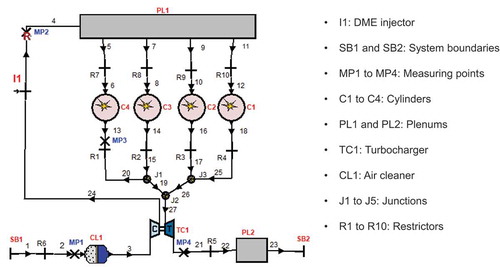
The model building procedure comprises steps including the model construction, selecting governing equations, and processing of initial data and boundary conditions. The simulation model of the 4BD1T engine () was developed in AVL Boost based on actual structure parameters such as the gas exchange system geometry, the volumes of plenums, the properties of the boost system, the engine combustion chamber geometry, the valve timing and lift diagrams and also the fuel system properties, injection rate profile, injection pressure and blow-by.
Figure 1. Simulation model of the 4BD1T engine
The first law of thermodynamics is used to calculate the pressure cycle of an ICE. In order to solve this equation, models for the combustion process and the wall heat transfer, as well as the gas properties as a function of pressure, temperature, and gas composition are required. The Woschni 1978 model (Woschni Citation1967) was used to determine the wall heat transfer coefficient. The friction model suggested by Patton (Patton, Nitschke, and Heywood Citation1989) had been selected to identify friction power, and the premix and diffusion combustion model was used for determining the rate of heat release and in-cylinder pressure profiles.
2.3. Selection combustion model
The combustion model and modelling methodology in AVL Boost software were developed by Chmela (Chmela, Orthaber and Schuster Citation1998, Chmela and Orthaber Citation1999). In the simulation process, DME fuel was supplied into the intake manifold as an external fuel, as a result, the vaporisation rate of fuel had to be considered. Meanwhile, diesel fuel was injected directly into the combustion chamber to form an internal mixing process. Therefore, the Mixing Controlled Combustion (MCC) model was selected to analyse the combustion process. The MCC model considers the effects of the premixed combustion (PMC) and diffusion controlled combustion processes, and heat release is calculated according to EquationEquation (1)
(1)
(1) :
The Vibe function was selected to describe heat release due to the premixed combustion as shown in EquationEquation (2)(2)
(2) and (Equation3
(3)
(3) ):
where is the total fuel heat input for the premixed combustion,
is the fuel heat input for the mixing controlled phase, α is the crank angle (CA) degree ,
is the premixed combustion duration, αid is the ignition delay timing, m is the shape parameter, and a is the Vibe parameter.
The ignition delay (ID), defined as the duration from the moment of the start of injection (SoI) and the moment of the start of combustion (SoC), was modelled as the combination of Arrhenius and Magnussen approaches (Magnussen and Hjertager Citation1976, Chmela, Pirker, and Wimmer Citation2007).
The released energy for mixing controlled phase is a function of the fuel quantity available (f1) and the turbulent kinetic energy density (f2), as shown in EquationEquation (4)(4)
(4) :
where ;
, CComb is the combustion constant, Crate is the mixing rate constant, k is the local density of turbulent kinetic energy, MF is the vaporised fuel mass, LHV is the lower heating value, Q is the cumulative heat release for the mixing controlled combustion and V is the cylinder volume.
2.4. Design of DME supplying system
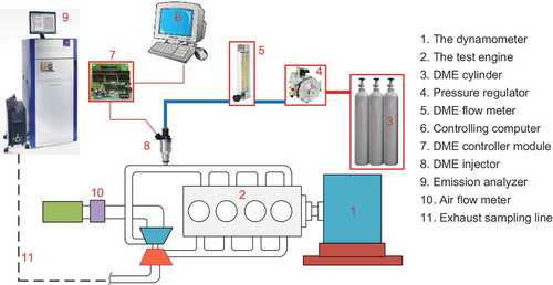
In this study, a fuel supplying system has been developed for the provision of DME into the intake manifold of the test engine as a fuel additive. The principal schematic of the system is presented in . As can be seen clearly in the schematic, a single-port sequential fuel injection system has been used. DME is stored in a pressurised cylinder and regulated to a suitable pressure before being injected into the intake manifold by a gaseous injector. The gaseous injector used in the test is a low resistant type and controlled by an electronic controller module according to testing conditions for a suitable proportion of fuel additive. In the experiment, the mass flow rate of DME supplied to the intake manifold has been guaranteed around a certain value to maintain a constant ratio to mass of intake air at each testing condition by controlling the injection frequency and duration. The flow rate of DME consuming can be measured directly by the flow meter device or calculated from the injection duration once the injector characteristic is known. In addition, the engine coolant has been recirculated to the pressure regulator for heat transferring. Therefore, the temperature and pressure of DME supplied to the injector have been guaranteed at a reasonable value.
Figure 2. The schematic of experiment system
2.5. Testing equipment
The testing equipment used in this study includes a dynamometer AVL-Alpha 160, fuel consumption measurement device, and emission measurement instruments. The dynamometer is controlled by dedicate software BOBCAT, which receives signals from sensors of the test engine and displays operating parameters in an easy to use visualisation. The flow rate of diesel fuel consumed by the test engine was determined by fuel balance equipment AVL PLU 116H. A glass tube flow meter was used in order to measure the flow rate of DME supplied to the engine while as the air flow rate consumption was measured by the Sensyflow 735 device. The AVL SESAM i60 FTIR (Fourier transformation infrared spectroscopy), a multi-component measurement system was used for exhaust emission evaluation. In addition, a smoke meter operating based on the principle of Filter paper blackening was used for determination of the smoke component. The specifications of the testing equipment are described in . The laboratory of the engine test rig is shown in .
Figure 3. Laboratory of the engine test rig
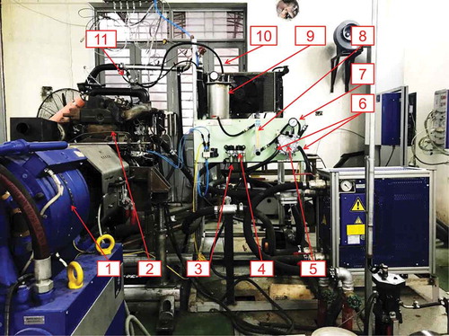
Table 3. Specifications of the testing equipment
Where 1 – Dynamometer; 2 – Test engine; 3 – DME fuel in; 4 – Solenoid valve; 5 – Pressure regulated vaporizator; 6 – Water in and out of vaporizator; 7 – Pressure meter; 8 – DME flow meter; 9 – Plenum, 10 – DME supplying line, 11 – DME injector.
2.6. Studying procedure
The simulation on performance characteristics of the engine when operating with DMEA was conducted at full load condition. The combustion parameters including in-cylinder and heat release profiles have been evaluated.
The experiment aims to evaluate the effects of DMEA on the pollutant level and performance characteristics of the test engine. During the experiment, the parameters including brake torque, speed, exhaust pollutants, diesel fuel consumption, the flow rate of DME, and intake air have been measured for comparison.
At full load condition, engine speed was varied in the range from 1000 to 2500 rpm with an interval of 200 rpm. At load condition, the diesel fuel supplied was controlled so that brake power output varied from 10 kW to maximum value with an interval of 10 kW. While as, the test engine speed was kept constantly at a value of 1600 rpm, at which the engine torque is maximum. In the case of operating with DMEA, at each testing condition, DME has been injected into the intake manifold as an external fuel at a constant proportion around a value of 0.1% (equivalent to 1000 ppm) to the mass flow rate of intake air. This value has been found and fixed during the experimental work. The test was carried out three times at every operating conditions and the average value of the results was used for assessment.
3. Results and discussion
3.1. Validation of simulation models
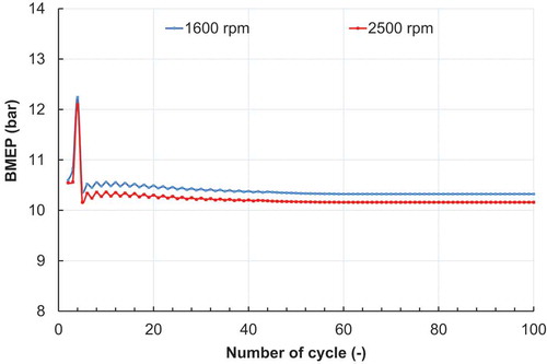
The results displayed in show the value of brake mean effective pressure (BMEP) as a function of simulated cycles at rate condition (2500 rpm, full load) and maximum torque condition (1600 rpm, full load). It can be observed, the value of BMEP is fluctuated at several first cycles and levelled off to a stable value at cycle number of 60th. Therefore, the simulated results are coverage, so simulation results could be used for comparison.
Figure 4. The simulated BMEP as a function of cycles at full load condition and an engine speed of 1600 rpm and 2500 rpm
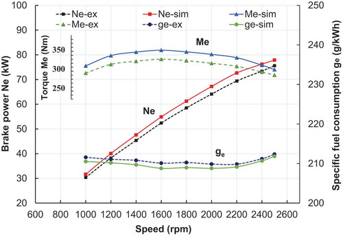
The simulation model was validated for a wide range of engine operating conditions via comparing the measured and simulated data as displayed in . The figure shows that simulation results for the brake power (BP) and brake specific fuel consumption (BSFC) curves at full load condition have the same trend as experiment results. This results verify that there is good agreement between the experiment and simulation. Brake power and BSFC curves obtained by simulation are differed by 2.3% on average compared to those obtained by experiment. Slight variation between the simulated and experimental data can be attributed to the assumption used in the simulation, which cannot be controlled in the experiment. However, the differences are trivial so the simulation models can be used for further determination of combustion parameters.
Figure 5. Comparison of brake power, torque and specific fuel consumption at full load condition
3.2. Comparisons of combustion parameters
The combustion parameters including the in-cylinder pressure and temperature as well as RoHR were exported from simulation results for comparison in the case of operating with and without DMEA. shows the comparison of the simulation results of the in-cylinder temperature and pressure profiles at maximum power condition. As can be seen on the chart, the in-cylinder pressure and temperature in the case of operating with DMEA are relatively higher compared to those of the original engine around the top dead centre (TDC). The peak difference can be observed around TDC, where the rate of burning reaches a peak value. The reduction in the in-cylinder pressure and temperature prior injection timing when running with DMEA is the result of the higher latent heat of vaporisation of the DME, 425 and 220 for DME and diesel fuel, respectively.
Figure 6. Comparison of in-cylinder temperature and pressure profiles at rate condition
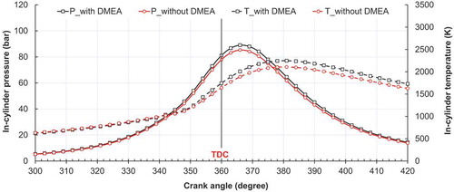
AVL Boost can predict the pressure raise cause by the premixing combustion process as a function of CA based on heat release. The max pressure raise (Δp/Δφ) is 3.09 bar/deg when the engine operating with pure diesel fuel. This parameter has a slight raise to 3.14 bar/deg as the engine running with DMEA. It can be concluded that the appearance of DME as external fuel contributes to an effect on the premix combustion process. As a result, the pressure raise as well as peak temperature and pressure in the case of operating with DMEA increase.
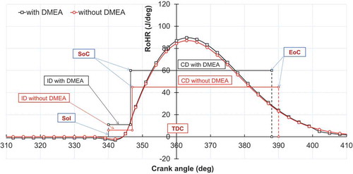
shows the comparison of combustion parameters, including the RoHR, ID, and combustion duration (CD) corresponding to the rate condition. The simulation results show that the higher latent heat of DME in charge air makes a trivial lower of in-cylinder temperature prior combustion delay process. However, the better pre-mixture of intake charge will result in the shorter ID when the engine is simulated with DMEA. In addition, the shorter ID may be the result of the higher cetane number and the lower flash point of DME in comparison with diesel fuel as shown in . However, the reduction of ID is trivial because the proportion of DME in the intake charge is relatively small. The CD of the engine running with DMEA, which is defined as the duration of 90% mass fraction burned, is also shorter than the case of without DMEA as clearly seen in the chart. Around the TDC, it can be seen clearly, there is a difference between the RoHR profiles. The peak value of the RoHR is 89.91 J/deg at a CA of 367 degrees for the case of operating with DMEA. While as, when the engine is simulated without DMEA, the peak value of the RoHR is 87.12 J/deg at a CA of 366 degrees.
Figure 7. Comparison of RoHR at rate condition
3.3. Assessment of DME supplying system
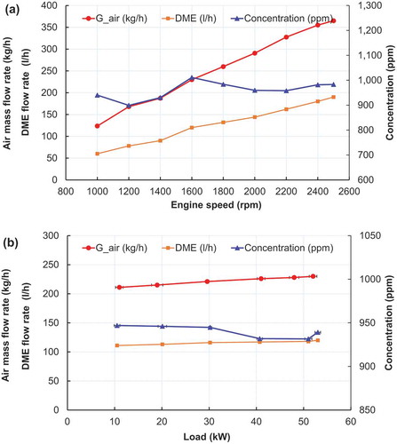
The measured values of the flow rate of intake air and DME at various operating conditions are presented in . At full load condition ( -a), as engine speed varies from 1000 to 2500 rpm, the concentration of DME to intake air fluctuates between 920 ppm and 1010 ppm. At an intermediate speed of 1600 rpm ( -b), the concentration varies from 940 ppm to 980 ppm. There is a slight deviation in the actual ratio of DME to intake air in comparison to the desire value (1000 ppm) because of the error in experiment measurement and adjustment of the DME supplying system, however, the deviation is trivial.
Figure 8. Assessment of DME supplying system (a) as a function of engine speed at full load condition and (b) as a function of load at an engine speed of 1600 rpm
3.2. The effects of DMEA on performance characteristics
presents the experimental results of brake power and brake specific energy consumption (BSEC) as a function of engine speed (9-a) and load condition (9-b) in the case of operating with and without DMEA. When operating with DMEA, the appearance of high reactivity fuel identified by the high cetane number and oxygen element contained will result in a more complete combustion process. The brake power of the test engine increases slightly by 3.25% on average at full load condition. For fuel economy evaluation when operating with DMEA, the BSEC parameter is used (Duc, Tien, and Duy Citation2018; Duc and Duy Citation2018). In this study, the BSEC parameter is used instead of BSFC because there is a difference in total energy input. Although the mass of DME supplied to the mass of intake air ratio is relatively small (1000 ppm) and DME has a relative lower LHV in comparison to diesel, 28.43 MJ/kg and 42.76 MJ/kg for DME and diesel, respectively, the absolute mass of DME supplied must be accounted for the total input energy for the test engine. Therefore, the determination of BSEC is based on the following equation:
Figure 9. Comparison of (a) brake power and BSEC as a function of engine speed at full load condition and (b) BSEC as a function of load at engine speed of 1600 rpm
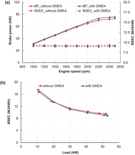
Where BSEC is the brake specific energy consumption (MJ/kWh), mD and mDME are mass flow of diesel and DME (kg/h), LHVD and LHVDME are the lower heating value of diesel and DME (MJ/kg), and BP is the brake power (kW).
The results show that the BSEC of the testing engine reduces approximately 2.20% on average at full load condition. While as, at an intermediate speed of 1600 rpm, the change of the BSEC has difference trend when load varies. At low load conditions, the BSEC increases slightly. However, as the load increases, the BSEC declines from 3.1% to 6.0%. The results can be specified that, the effects of DME depend on the mixture composition. At low load condition, the mixture is relatively lean so that DME will not play important role in combustion improvement. However, the implementation of DME can promote the combustion process, which results in the achievement of engine performance and fuel economy, especially at high load regimes, when the mixture is rich.
3.2. The effects of DMEA on exhaust pollutants
In this research, gas emissions and particulate matter (PM) have been measured and evaluated according to the steady state at full load condition and constant engine speeds, and at an intermediate speed of 1600 rpm when controlling the brake load, and the results are shown from to 14. The experimental results show that using DMEA in a compress ignition engine will contribute to a reduction in PM and CO. However, NOx and HC emission has changed in the opposite trend.
Figure 10. Comparison of smoke pollutant (a) as a function of engine speed at full load condition and (b) as a function of load condition at an engine speed of 1600 rpm
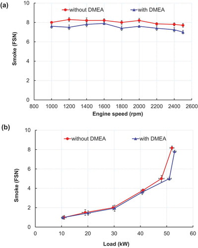
As clearly explained in literatures (Kitamura et al. Citation2002; Alriksson and Denbratt Citation2006), soot is generally formed in low air excess ratio and high-temperature condition. In the fuel-rich region, acetylene is formed by the decomposition of long-chain alkanes of diesel fuel. However, soot precursors decrease with the existence of oxygen content and lack of carbon-carbon bond in fuel molecular structure. The experimental result presented in -a identifies that, when the test engine operates with DMEA, the measured smoke level reduces from 4.94% to 9.64% at full load condition. While as, at intermediate speed, smoke level reduces from 2.0% to 8.2% as load increases in the case of operating with DMEA ( -b). The results can be identified that because DME has its own oxygen and no carbon-carbon structure in molecules, which result in fewer precursors formation during combustion process. In addition, at the end of compression stroke, there is homogeneous mixture of DME and charged air that will reduce fuel rich regimes in combustion chamber prior to injection moment. Consequently, the combustion process produces less PM when the engine operates with DMEA.
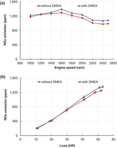
The NOx emission in the case of operating with DMEA increases moderately in comparison to the case of without DMEA at both full load and partial load conditions. The raise of NOx level is the result of higher in-cylinder temperature and the appearance of oxygen atoms in fuel molecular (Raine, Stone, and Gould Citation1995; Velmurugan and Sathiyagnanam Citation2017). Moreover, DME owns a high cetane number and excellent vaporisation ability, which result in a rapid combustion reaction once diesel to be injected into the combustion chamber. Also, the oxygen content in molecular acts as an oxidiser that will promote the combustion reaction and make combustion temperature rose. It is found that the NOx emission increases by 5.62% on average compared with that of the original engine at full load condition, and 7.1% on average at intermediate speed as shown in .
Figure 11. Comparison of NOx emission (a) as a function of engine speed at full load condition and (b) as a function of load at an engine speed of 1600 rpm
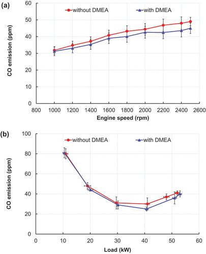
In this experimental study, the CO emission reduces moderately as the engine operates with DMEA. It can be observed in , when the test engine operates with DMEA, CO level is approximately 5.28% lower on average at full load condition and 5.9% on average at an intermediate speed of 1600 rpm. As explained clearly in literatures (Iodice and Senatore Citation2016; Knapp, Stump, and Tejada Citation1998), the CO emission of an ICE results when fuel supplied to the engine does not burn completely, under too rich or too lean regimes. In the case of operating with DMEA, CO emission is lower in compared to that of the original engine because DME is specified by the lower C/H ratio, no carbon-carbon bonds, and has oxygen content in molecular (see in ), which result in a good mixture formation and fast oxidation of intermediate species. For both cases, at low load conditions, the mixture of air and fuel is too lean that results in a high CO level. Then the CO level reduces to reach the lowest value at medium load before rising gradually as the load increases. At high load condition, the CO level increases because there are more rich regimes in the combustion chamber.
Figure 12. Comparison of CO emission (a) as a function of engine speed at full load condition and (b) as a function of load condition at an engine speed of 1600 rpm
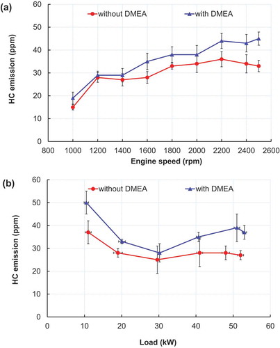
In opposite to the variation of CO, the HC level tends to increase when the engine operating with DMEA (see ). At full load condition, HC increases gradually from 3.57% to 26.67% in speed range varied from 1000 to 2500 rpm. While as at an engine speed of 1600 rpm, the HC fluctuates as the load changing. However, in compared to the case of without DMEA, HC increases 27.5% on average when the engine operating with DMEA. The increase in HC level when the engine operating with DMEA is the result of the external mixture formation between DME and intake air. The intake charge of the test engine is similar to that of a spark ignition engine which has higher HC level in comparison with compress ignition engine (Springer and Patterson Citation1973).
Figure 13. Comparison of HC emission (a) as a function of engine speed at full load condition and (b) as a function of load condition at an engine speed of 1600 rpm
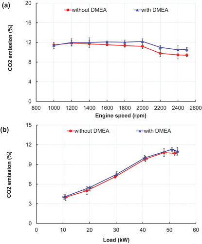
The results in show that the amount of CO2 emitted as the engine operates with DMEA tends to increase 4.95% and 1.27% on average at full load and partial load conditions, respectively. These results are consistent with the reduction of CO and smoke as the combustion process is more effective with the appearance of DME in the intake charge.
Figure 14. Comparison of CO2 emissions (a) as a function of engine speed at full load condition and (b) as a function of load at an engine speed of 1600 rpm
4. Conclusion
In this research, an experiment and simulation study on the pollutant reduction and performance enhancement of an old generation diesel engine operating with DME enriched air had been conducted. The simulation results show that DME used as fuel additive has effects on combustion process of the engine. The in-cylinder temperature and pressure increase slightly around TDC because of the better combustion process. The ignition delay and combustion duration are shorter when the engine has been simulated with DMEA. The experiment results show that using DME supplied into the intake manifold is a good solution for smoke reduction while as, the performance and fuel economy of the engine has a slight improvement. The smoke and CO level reduce considerably at high load condition when the engine operating with DMEA but NOx and HC increase in the opposite tendency. The designed DME supplying system in this study is a simple and low-cost solution, which can be applied widely in old generation diesel engines for pollutants reduction because it does not affect other systems of the original engines.
Abbreviations
The total fuel heat input for the premixed combustion
The fuel heat input for the mixing controlled phase
αThe crank angle degree
The pre-mixed combustion duration
αidThe ignition delay timing
mThe shape parameter
aThe Vibe parameter
IDIgnition delay
CDCombustion duration
SoIStart of injection
SoCStart of combustion
EoCEnd of combustion
f1Fuel quantity available
f2The turbulent kinetic energy density
CCombThe combustion constant
CrateThe mixing rate constant
kThe local density of turbulent kinetic energy
MFThe vaporized fuel mass
LHVThe lower heating value
Qthe cumulative heat release for the mixing controlled combustion
VThe cylinder volume
Heat release
Δp/ΔφPressure raise
mDmass flow of diesel
mDMEmass flow of DME
LHVDThe lower heating value of diesel
LHVDMEThe lower heating value of DME
Nomenclatures
BTDCBefore top dead central
FTIRFourier transformation infrared spectroscopy
NDIRNon dispersive infrared
FIDFlame ionization detector
PMDParamagnetic detector
FSNFilter smoke number
MCCMixing controlled combustion
PMCPremixed combustion
RoHRRate of heat release
BMEPBrake mean effective pressure
BSFCBrake specific fuel consumption
BSECBrake specific energy consumption
BPBrake power
Acknowledgments
This work was supported by the Lab of Internal Combustion Engines, University of Transport Technology (UTT), Hanoi, Vietnam.
Disclosure statement
No potential conflict of interest was reported by the authors.
Additional information
Notes on contributors
Doan Nguyen Cong
Doan Nguyen Cong is lecturer at Faculty of Mechanical Engineering, University of Transport Technology, Hanoi, Vietnam. He is an expert in field of ship power plants, alternative fuels for internal combustion engine, heat transfer.
Khanh Nguyen Duc
Khanh Nguyen Duc is lecturer at School of Transportation Engineering, Hanoi University of Science and Technology, Hanoi, Vietnam. He is an expert in field of mechanical engineering, automatic control, emission from internal combustion engine, alternative fuels for internal combustion engine.
Vinh Nguyen
Vinh Nguyen is lecturer at Faculty of Vehicle and Energy Engineering, Phenikaa University, Hanoi, Vietnam. He is an expert in field of mechanical engineering, fuel cell, internal combustion engine, alternative fuels for internal combustion engine.
References
- Alriksson, M., and I. Denbratt. 2006. “Low Temperature Combustion in a Heavy Duty Diesel Engine Using High Levels of EGR.” SAE Technical Paper Series. doi:https://doi.org/10.4271/2006-01-0075.
- Banapurmath N. R., Y. H. Basavarajappa and P. G. Tewari. 2012. “Effect of mixing chamber venturi, injection timing, compression ratio and EGR on the performance of dual-fuel engine operated with HOME and CNG.” International Journal of Sustainable Engineering 5 (3): 265–279. doi: https://doi.org/10.1080/19397038.2011.603847.
- Bek, B. H., and S. C. Sorenson. 2001.“A Mixing Based Model for Di-methyl Ether Combustion in Diesel Engines.”Journal of Engineering for Gas Turbines and Power 123 (3): 627–632. doi: https://doi.org/10.1115/1.1362665.
- Chmela, F., and G. Orthaber. 1999. “Rate of Heat Release Prediction for Direct Injection Diesel Engines Based on Purely Mixing Controlled Combustion” SAE Technical Paper 1999-01-0186. doi:https://doi.org/10.4271/1999-01-0186.
- Chmela, F., G. Orthaber, and W. Schuster. 1998. “Die Vorausberechnung des Brennverlaufs von Dieselmotoren mit direkter Einspritzung auf der Basis des Einspritzverlaufs.” MTZ - Motortechnische Zeitschrift 59 (7–8): 484–492. doi:https://doi.org/10.1007/BF03226471.
- Chmela, F. G., G. H. Pirker, and A. Wimmer. 2007. “Zero-dimensional ROHR Simulation for DI Diesel Engines – A Generic Approach.” Energy Conversion and Management 48 (11): 2942–2950. doi:https://doi.org/10.1016/j.enconman.2007.07.004.
- Cucchi, M., and S. Samuel. 2015. “Influence of the Exhaust Gas Turbocharger on Nano-scale Particulate Matter Emissions from a GDI Spark Ignition Engine.„ Applied Thermal Engineering 76:167–174. doi:https://doi.org/10.1016/j.applthermaleng.2014.11.002.
- Duc, K. N., H. N. Tien, and V. N. Duy. 2018. “Performance Enhancement and Emission Reduction of Used Motorcycles Using Flexible Fuel Technology.” Journal of the Energy Institute 91 (1): 145–152. doi:https://doi.org/10.1016/j.joei.2016.09.004.
- Duc, K. N., and V. N. Duy. 2018. “Study on Performance Enhancement and Emission Reduction of Used Fuel-Injected Motorcycles Using Bi-Fuel Gasoline-LPG.” Energy for Sustainable Development 43: 60–67. doi:https://doi.org/10.1016/j.esd.2017.12.005.
- Duy, V. N., K. N. Duc, T. N. Thanh, L. H. Dinh, and T. Le Anh. 2020. “Implementation of Fuel Additive MAZ 100 for Performance Enhancement of Compressed Natural Gas Engine Converted from In-used Gasoline Engine.” Journal of the Air & Waste Management Association 70 (9): 932–943. doi:https://doi.org/10.1080/10962247.2020.1781709.
- Fang, Q., Z. Huang, L. Zhu, -J.-J. Zhang, and J. Xiao. 2011. “Study on Low Nitrogen Oxide and Low Smoke Emissions in a Heavy-duty Engine Fuelled with Dimethyl Ether.” Proceedings of the Institution of Mechanical Engineers, Part D: Journal of Automobile Engineering 225 (6): 779–786. doi:https://doi.org/10.1177/2041299110394513.
- Gao, J., G. Tian,A. Sorniotti, A. Ece Karci, and R. Di Palo. 2018. “Review of thermal management of catalytic converters to decrease engine emissions during cold start and warm up.” Applied Thermal Engineering 147: 177–187. doi:https://doi.org/10.1016/j.applthermaleng.2018.10.037
- Golovitchev, V., N. Nordin,and J. Chomiak. 1998. “Neat Dimethyl Ether: Is It Really Diesel Fuel of Promise?” SAE Technical Paper Series 982537. doi: https://doi.org/10.4271/982537.
- Hoang, A. T., A. T. Le, and V. V. Pham. 2019. “A Core Correlation of Spray Characteristics, Deposit Formation, and Combustion of A High-speed Diesel Engine Fueled with Jatropha Oil and Diesel Fuel.” Fuel 244: 159–175. doi:https://doi.org/10.1016/j.fuel.2019.02.009.
- Hoang, A. T., V. D. Tran, V. H. Dong, and A. T. Le. 2019. “An Experimental Analysis on Physical Properties and Spray Characteristics of an Ultrasound-assisted Emulsion of Ultra-low-sulphur Diesel and Jatropha-based Biodiesel.„Journal of Marine Engineering & Technology, 1–9. doi:https://doi.org/10.1080/20464177.2019.1595355.
- Iodice, P., and A. Senatore. 2016. “New Research Assessing the Effect of Engine Operating Conditions on Regulated Emissions of a 4-stroke Motorcycle by Test Bench Measurements.” Environmental Impact Assessment Review 61: 61–67. doi:https://doi.org/10.1016/j.eiar.2016.07.004.
- Kim, M. Y., S. H. Yoon, B. W. Ryu, and C. S. Lee. 2008. “Combustion and Emission Characteristics of DME as an Alternative Fuel for Compression Ignition Engines with a High Pressure Injection System.” Fuel 87 (12): 2779–2786. doi:https://doi.org/10.1016/j.fuel.2008.01.032.
- Kitamura, T., T. Ito, J. Senda, and H. Fujimoto. 2002. “Mechanism of Smokeless Diesel Combustion with Oxygenated Fuels Based on the Dependence of the Equivalence Ration and Temperature on Soot Particle Formation.” International Journal of Engine Research 3 (4): 223–248. doi:https://doi.org/10.1243/146808702762230923.
- Knapp, K. T., F. D. Stump, and S. B. Tejada. 1998. “The Effect of Ethanol Fuel on the Emissions of Vehicles over a Wide Range of Temperatures.” Journal of the Air & Waste Management Association 48 (7): 646–653. doi:https://doi.org/10.1080/10473289.1998.10463710.
- Lecksiwilai, N., S. H. Gheewala, M. Sagisaka, and K. Yamaguchi. 2016. “Net Energy Ratio and Life Cycle Greenhouse Gases (GHG) Assessment of Bio-dimethyl Ether (DME) Produced from Various Agricultural Residues in Thailand.” Journal of Cleaner Production 134: 523–531. doi:https://doi.org/10.1016/j.jclepro.2015.10.085.
- Lee, S., S. Oh, Y. Choi, and K. Kang. 2011. “Performance and Emission Characteristics of a CI Engine Operated with n-Butane Blended DME Fuel.” Applied Thermal Engineering 31 (11–12): 1929–1935. doi:https://doi.org/10.1016/j.applthermaleng.2011.02.039.
- Magnussen, B. F., and B. H. Hjertager. 1977. “On Mathematical Modeling of Turbulent Combustion with Special Emphasis on Soot Formation and Combustion.” Symposium (International) on Combustion 16 (1): 719–729. doi:https://doi.org/10.1016/s0082-0784(77)80366-4.
- Meng, Z., C. Chen, J. Li, J. Fang, J. Tan, Y. Qin, Y. Jiang, and K. Liang. 2020. “Particle Emission Characteristics of DPF Regeneration from DPF Regeneration Bench and Diesel Engine Bench Measurements.” Fuel 262: 116589. doi:https://doi.org/10.1016/j.fuel.2019.116589.
- Nguyen, T., M. Pham, and T. L. Anh. 2020. “Spray, Combustion, Performance and Emission Characteristics of a Common Rail Diesel Engine Fueled by Fish-oil Biodiesel Blends.” Fuel 269: 117108. doi:https://doi.org/10.1016/j.fuel.2020.117108.
- Park, S. H., J. Cha, S. Park, and C. S. Lee. 2012. “Simultaneous Reduction in the Exhaust Emissions by a High Exhaust Gas Recirculation Ratio in a Dimethyl-ether-fuelled Diesel Engine at a Low-load Operating Condition.„ Proceedings of the Institution of Mechanical Engineers, Part D: Journal of Automobile Engineering 226 (8): 1130–1142. doi:https://doi.org/10.1177/0954407012439502.
- Patton, K., R. Nitschke, and J. Heywood. 1989. “Development and Evaluation of a Friction Model for Spark-Ignition Engines.” SAE Technical Paper 890836. doi:https://doi.org/10.4271/890836.
- Praveena, V., and M. L. J. Martin. 2018. “A Review on Various after Treatment Techniques to Reduce NOx Emissions in A CI Engine.” Journal of the Energy Institute 91 (5):704–720. doi:https://doi.org/10.1016/j.joei.2017.05.010.
- Raine, R. R., C. R. Stone, and J. Gould. 1995. “Modeling of Nitric Oxide Formation in Spark Ignition Engines with a Multizone Burned Gas.” Combustion and Flame 102 (3): 241–255. doi:https://doi.org/10.1016/0010-2180(94)00268-w.
- Resitoglu, I. A., K. Altinisik, A. Keskin, and K. Ocakoglu. 2019. “The Effects of Fe2O3 Based DOC and SCR Catalyst on the Exhaust Emissions of Diesel Engines.” Fuel 262: 116501. doi:https://doi.org/10.1016/j.fuel.2019.116501.
- Schütt, M., M. Gallinger, and R. Moos. 2017. “Particulate Filter Substrates with SCR-Functionality Manufactured by Co-extrusion of Ceramic Substrate and SCR Active Material.” Topics in Catalysis 60 : 204–208. doi:https://doi.org/10.1007/s11244-016-0598-7.
- Sezer, İ. 2011. “Thermodynamic, Performance and Emission Investigation of a Diesel Engine Running on Dimethyl Ether and Diethyl Ether.” International Journal of Thermal Sciences 50 (8): 1594–1603. doi:https://doi.org/10.1016/j.ijthermalsci.2011.03.021.
- Sorenson, S. C. 2001. “Dimethyl Ether in Diesel Engines: Progress and Perspectives-transactions of the ASME.”Journal of Engineering for Gas Turbines and Power 123 (3): 652–658. doi:https://doi.org/10.1115/1.1370373.
- Springer, G. S., and D. J. Patterson. 1973. Engine Emissions.Springer, Boston, MA. doi:https://doi.org/10.1007/978-1-4684-1983-2.
- Theinnoi, K., P. Suksompong, and W. Temwutthikun. 2017. “Engine Performance of Dual Fuel Operation with In-cylinder Injected Diesel Fuels and In-Port Injected DME.” Energy Procedia 142: 461–467. doi:https://doi.org/10.1016/j.egypro.2017.12.072.
- Thomas, G., B. Feng, A. Veeraragavan, M. J. Cleary, and N. Drinnan. 2014. “Emissions from DME Combustion in Diesel Engines and Their Implications on Meeting Future Emission Norms: A Review.” Fuel Processing Technology 119: 286–304. doi:https://doi.org/10.1016/j.fuproc.2013.10.018.
- Velmurugan, K., and A. P. Sathiyagnanam. 2017. “Effect of Biodiesel Fuel Properties and Formation of NOX Emissions: A Review.” International Journal of Ambient Energy 38 (6): 644–651. doi:https://doi.org/10.1080/01430750.2016.1155486.
- Verbeek, R., and J. Van Der Weide. 1997. “Global Assessment of Dimethyl Ether: Comparison with Other Fuels.” SAE Technical Paper Series 971607.doi:10.4271/971607.
- Wakai, K., K. Nishida, T. Yoshizaki, and H. Hiroyasu. 1999. “Ignition Delays of DME and Diesel Fuel Sprays Injected by a D.I. Diesel Injector.”SAE Technical Paper 1999-01-3600. doi:https://doi.org/10.4271/1999-01-3600.
- Woschni, G. 1967. “A Universally Applicable Equation for the Instantaneous Heat Transfer Coefficient in the Internal Combustion Engine.” SAE Technical Paper 670931. doi:https://doi.org/10.4271/670931.
- Youn, I. M., S. H. Park, H. G. Roh, and C. S. Lee. 2011. “Investigation on the Fuel Spray and Emission Reduction Characteristics for Dimethyl Ether (DME) Fueled Multi-cylinder Diesel Engine with Common-rail Injection System.” Fuel Processing Technology 92 (7): 1280–1287. doi:https://doi.org/10.1016/j.fuproc.2011.01.018.
- Zhao, Y., Y. Wang, D. Li, X. Lei, and S. Liu. 2014. “Combustion and Emission Characteristics of a DME (Dimethyl Ether)-diesel Dual Fuel Premixed Charge Compression Ignition Engine with EGR (Exhaust Gas Recirculation).” Energy 72: 608–617. doi:https://doi.org/10.1016/j.energy.2014.05.086.