
ABSTRACT
Smart polymeric and gel actuators change shape or size in response to stimuli like electricity, heat, or light. These smart polymeric- and gel-based actuators are compliant and well suited for development of soft mechatronic and robotic devices. This paper provides a thorough review of select smart polymeric and gel actuator materials where an automated and freeform fabrication process, like 3D printing, is exploited to create custom shaped monolithic devices. In particular, the advantages and limitations, examples of applications, manufacturing and fabrication techniques, and methods for actuator control are discussed. Finally, a rigorous comparison and analysis of some of the advantages and limitations, as well as manufacturing processes, for these materials, are presented.
1. Introduction
This paper provides a thorough review of select smart polymeric and gel actuators for use in mm to cm scale 3D printed soft mechatronic and robotics applications. These innovative smart polymeric- and gel-based actuators change shape or size in response to stimuli like electricity, heat, or light. For instance, ionic polymer metal composites (IPMCs) are composites (of ion exchange materials and electrodes) that bend in response to an applied voltage, as shown in )–(); ionic gels are polymerized mixtures (of ionic liquids and vinyl monomers) that deform in response to an electric field applied in an electrolytic environment, as shown in )-(); shape memory polymers (SMP)s are any polymeric material that exhibits the ability to ‘freeze’ in and release from a deformed shape in response to heat, solvent and/or light, as shown in )-(); and liquid crystal polymers are polymers with mesogenic groups that undergo liquid crystal phase transitions in response to light and or heat causing the material to change shape or size, as shown in )-(). Smart polymeric actuators are an enabling technology for soft miniature mechatronic and robotic systems like micromanipulators and miniature mobile platforms [Citation1]. Moreover, smart polymeric materials can also be used in, micro-machining and other monolithic, free-form manufacturing techniques such as 3D printing [Citation2–Citation10], as shown in . This allows the fabrication of custom soft devices with intrinsic actuation capability, without needing to assemble the printed body with actuators and sensors.
Figure 1. Freeform fabrication of robotic and shape-changing devices using smart polymeric materials: (a1) fused-filament fabrication (3D printing) of IPMC soft crawling robot, (a2) locomotion of 3D-printed IPMC-based crawling robot, and (a3) photo of 3D-printed IPMC-based crawling robot crawling along a tube; (b1) fabrication of an ionogel-based crawling robot, (b2) locomotion of an ionogel-based crawling robot, (b3) photo of an ionogel-based crawling robot crawling along a PDMS substrate; (c1) micro-projection stereolithographic (µSLA) fabrication of a SMP based flower, (c2) restoration of SMP flowers unstrained shape in response to heat, and (c3) picture of SMP flower in its unstrained shape; (d1) inkjet printing and micromachining of a phototropic liquid crystal elastomer (LCE) based artificial cilia array, (d2) actuation cycle of LCE based artificial cilia array in response to visible and UV light, and (d3) picture of actuating LCE based artificial cilia array exhibiting fast response time. Figures (a1)-(a3) adapted with permission from [Citation11]. Figures (b1)-(b3) adapted with permission from [Citation7]. Figures (c1)-(c3) adapted with permission from [Citation9]. Figures (d1)-(d3) adapted with permission from [Citation6].
![Figure 1. Freeform fabrication of robotic and shape-changing devices using smart polymeric materials: (a1) fused-filament fabrication (3D printing) of IPMC soft crawling robot, (a2) locomotion of 3D-printed IPMC-based crawling robot, and (a3) photo of 3D-printed IPMC-based crawling robot crawling along a tube; (b1) fabrication of an ionogel-based crawling robot, (b2) locomotion of an ionogel-based crawling robot, (b3) photo of an ionogel-based crawling robot crawling along a PDMS substrate; (c1) micro-projection stereolithographic (µSLA) fabrication of a SMP based flower, (c2) restoration of SMP flowers unstrained shape in response to heat, and (c3) picture of SMP flower in its unstrained shape; (d1) inkjet printing and micromachining of a phototropic liquid crystal elastomer (LCE) based artificial cilia array, (d2) actuation cycle of LCE based artificial cilia array in response to visible and UV light, and (d3) picture of actuating LCE based artificial cilia array exhibiting fast response time. Figures (a1)-(a3) adapted with permission from [Citation11]. Figures (b1)-(b3) adapted with permission from [Citation7]. Figures (c1)-(c3) adapted with permission from [Citation9]. Figures (d1)-(d3) adapted with permission from [Citation6].](/cms/asset/71cadfb6-dedf-4ee7-9c6d-66791aab21de/tsnm_a_1438534_f0001_c.jpg)
As examples, crawling robots have been fabricated completely out of 3D-printed IPMC material [Citation11] and laser-cut ionogel material [Citation7], as shown in a1)-(b3); shape changing parts such as a flowers have been fabricated from SMPs using projection micro-stereolithography (µSLA) [Citation9], as shown in )-(), and an artificial cilia array has been fabricated using inkjet printing and micromachining techniques to deposit and etch liquid crystal elastomer [Citation6], as shown in )-(). However, a guide is needed for choosing smart polymeric or gel actuator material for a given application; specifically, for use in fabricating monolithic smart polymeric mechatronic and robotic devices. Therefore, this paper provides a thorough review of select smart polymeric and gel actuators that have been demonstrated for use in soft mechatronic and soft robotic applications and have been manufactured using a monolithic freeform fabrication technique such as 3D printing. This paper also compares performance parameters for these materials, identifies potential applications based on their advantages, and introduces methods for fabrication and motion control. Finally, a comparison of freeform fabrication techniques used to create monolithic devices out of these materials is made and challenges and limitations are presented.
Smart polymeric and gel actuators have numerous advantages compared to traditional actuators and even other smart-material actuators such as piezoelectric actuators. For instance, they are able to safely operate near humans since they are compliant [Citation1,Citation12]. Smart polymeric actuators allow inexpensive mass production, have fewer components, and are easier to miniaturize than traditional actuators [Citation1]. Smart polymeric actuators can also absorb impulsive loads and are light weight, like other soft robotic materials [Citation13]. For this reason, these actuators have been applied to a variety of applications. For instance, IPMCs have been used to create serial and parallel manipulators [Citation14,Citation15], grippers [Citation16], and propulsors for generating locomotion in underwater systems [Citation17–Citation19]. Dielectric elastomer actuators (DEAs) and related polyvinyl gel artificial muscles (PVCAM) have been used to create a variety of crawling robots [Citation20,Citation21]. Shape memory polymers have been employed as ingestible origami robots [Citation22] and a 3D-printed gripper [Citation9]. Liquid crystal polymers have been used as artificial muscles [Citation23], artificial cilia arrays [Citation6], and a crawling device [Citation24].
However, use of soft polymeric and gel actuators in applications such as small manipulators and small locomotive platforms requires suitable materials and manufacturing methods. For instance, the material must be capable of the response time, stroke and material stress required, and the manufacturing process should be able to easily produce a variety of custom designs. Recent work provides a comprehensive review of soft actuators that spans multiple material types and performance ranges that may consequentlyhave very different ideal applications [Citation1]. While the review offered in [Citation1] is valuable for covering all soft actuators it does not focus on any subset of materials selected for use in a particular manufacturing paradigm and application because of its large scope.
The contribution of this paper is a thorough review of select polymeric- and gel-based actuators that have the potential to be used in soft mechatronics and robotics (such as manipulators and locomotive platforms) and have been manufactured through some type of freeform fabrication technique such as 3D printing. This paper describes the advantages of each material, suitable applications for them, and the manufacturing processes for fabricating them, with special emphasis on free-form fabrication techniques. Known challenges to controlling the materials and ways to address these challenges are also identified. Additionally, this paper reiterates and expands on comparisons of critical performance characteristics for the selected materials, acknowledging a debt to prior reviews [Citation1,Citation25–Citation32]. This paper also makes an independent contribution by demonstrating custom-shaped monolithic 3D-printed IPMC actuators fabricated using a fused-filament fabrication technique and comparing them to analogous systems assembled from conventional IPMC bending actuators.
The rest of this paper is dedicated to the specific types of actuators that will be discussed and is organized as follows: Section 2 deals with IPMCs as well as similar composites with non-metallic electrodes; Section 3 deals with conjugated polymers and ionic gel actuators; Section 4 deals with shape memory polymer actuators; Section 5 deals with liquid crystal polymer actuators; Section 6 briefly addresses other commonly used and promising soft actuator materials; Section 7 presents an in-depth analysis and comparison of the actuator materials, suitable applications and their manufacturing methods. Finally, concluding remarks are made in Sec. 8.
2. Ionic polymer metal composites
This section will begin by introducing what IPMCs are, how they work, and their advantages and applications. Next, this section will discuss conventional materials and manufacturing methods for IPMCs, as well as automated and freeform adaptations of these techniques. This will include a recently developed method using fused filament fabrication (3D printing) to create custom shaped monolithic IPMCs that exhibit complex motion [Citation8, Citation33]. The actuation response of 3D-printed, custom-shaped, monolithic IPMC actuators will be presented and compared to similar actuators constructed by assembling bending style actuators with other passive components. Finally, this section discusses challenges to motion control of IPMCs as well as strategies for addressing them.
2.1. Composition, mechanics, and advantages
As shown in ), an IPMC is a composite of an ion-exchange membrane (an ionomer) and conductive electrode layers which are often noble metals such as platinum or gold [Citation26]. Ion exchange membranes have ionic groups that are neutralized by a counterionic species, as shown in ). When a voltage is applied across the electrodes of a hydrated IPMC (with a negatively charged ionexchange membrane), the counterions (positively charged) rapidly migrate towards the cathode in response to the electric field [Citation34–Citation36]. This is immediately followed by a mechanical bending toward the anode, as shown in ). The counterion transport is attributed as a cause of IPMC actuation and sensing [Citation26,Citation35,Citation37,Citation38]. For instance, physics based models of IPMC actuation generally take the form of a Poisson–Nernst–Planck (PNP) system to calculate counterion concentration and electric potential within the ionomer and an electromechanical eigenstress is assumed to be proportional to the charge density [Citation35].
Figure 2. Structure and mechanics of actuation of IPMCs: (a) IPMC composed of platinum electrodes and a Nafion ionomer, (b) molecular composition of Nafion in its acid form (with H+ neutralized end groups), (c) IPMCs, exhibiting even distribution of hydrated cations within the ion-exchange membrane and (d) response of a hydrated IPMC to an applied voltage across its electrodes, exhibiting the migration of hydrated cations towards the cathode and a resulting bending towards the anode. Figures (a) and (b) taken with permission from [Citation222].
![Figure 2. Structure and mechanics of actuation of IPMCs: (a) IPMC composed of platinum electrodes and a Nafion ionomer, (b) molecular composition of Nafion in its acid form (with H+ neutralized end groups), (c) IPMCs, exhibiting even distribution of hydrated cations within the ion-exchange membrane and (d) response of a hydrated IPMC to an applied voltage across its electrodes, exhibiting the migration of hydrated cations towards the cathode and a resulting bending towards the anode. Figures (a) and (b) taken with permission from [Citation222].](/cms/asset/8f77a746-8a39-44b5-859e-11da9853ba6c/tsnm_a_1438534_f0002_c.jpg)
As smart polymeric actuators, IPMCs have the advantages of low actuation voltage (<3V), time response on the order of seconds, continuous operation in aqueous environments, functionality from nanometer to centimeter scales, and the potential to be used as sensors [Citation1,Citation27,Citation39]. Moreover, it has been demonstrated in several studies that IPMCs exhibit impressively linear actuator and sensor responses over a wide range of frequencies, when considering the correlation of voltage to bending curvature [Citation35]. For instance [Citation40], illustrates that peak open circuit voltage is linearly proportional to the bending angle of cantilevered IPMCs at higher bending rates (>45ο s−1) and [Citation41] suggests that the sensor response of IPMCs is well described by a linearized form of the PNP system, which neglects nonlinear electromigration.
The disadvantages of IPMCs include a lower work density (5.5 kJ/m3) than dielectric elastomer actuators (DEAs) and other electroactive polymers (EAPs) [Citation1], non-repeatability [Citation42] and a dynamic sensor response [Citation39]. Also, some IPMCs exhibit back-relaxation in response to low frequency inputs [Citation42, Citation43]. Additionally, IPMCs can be damaged if the input voltage exceeds the decomposition voltage of their hydrating solvent [Citation44] or if the electrodes are cracked as may happen if the IPMC is allowed to dry out [Citation45]. Other notable investigations of IPMC composition, mechanics and advantages and related studies include [Citation46–Citation59].
2.2. Applications
IPMCs are ideal for applications that leverage their low actuation voltage, flexibility, large bending response, and functionality in aqueous environments. This makes them attractive in micrometer-scale to centimeter-scale robotics, and biomedical applications. IPMC micromanipulators can potentially replace costly traditional systems for tasks such as biological cell handling or manipulation of other sensitive biological specimens [Citation14,Citation15]. The composite material’s inherent compliance has been leveraged for use in stiffness control of a micro-gripper in a peg-in-hole assembly task [Citation16]. Because they can operate in aqueous environments, IPMCs have also been used to create artificial fins for silent, monolithic propulsion mechanisms in underwater vehicles [Citation60–Citation63]. The bending locomotion of IPMCs also make them useful for developing crawling or swimming robots that employ serpentine locomotion [Citation64]. They have also been used in microfluidic valves and pumps [Citation65], catheters [Citation66], and endoscopes [Citation67].
2.3. Conventional manufacturing and materials
Manufacturing IPMCs consists of two conceptually distinct parts: (1) shaping the ionomeric material and (2) developing electrodes on the surface of the ionomeric material. This subsection will first discuss ionomeric materials used in IPMCs. This will include the properties of these materials that influence IPMC performance and the advantages and disadvantages of some example materials. This will be followed by a discussion of how to shape ionomeric materials. Finally, this section will conclude by addressing methods and materials used to develop electrodes on the surface of the ionomeric material.
2.3.1. Ionomeric materials for IPMCs
The ionomeric materials employed in IPMCs are often referred to as ion-exchange membranes or polyelectrolytes. These ionomers will swell if immersed in a solvent but maintain their structural integrity. Phase separation of the hydrophobic polymer from its hydrophilic ionic groups results in a network that conducts hydrated ions in the material. Some examples of the large variety of ion-exchange materials that are used in IPMCs and other ionic polymer actuators are listed in . As exhibited in , IPMCs have been fabricated using both perfluorosulfonic membranes such as Nafion as well as a variety of sulfonated hydrocarbons, such as sulfonated polystyrene [Citation68–Citation75].
Table 1. Ion exchange/poly-electrolyte materials for use in ionic polymer metal composites and other ionic polymer actuators. All values pertain to the acid(H+) form unless specified differently. Costs are from Sigma-Aldrich.
Ion-exchange membranes for IPMCs are selected to have high water uptake, ion-exchange capacity, and conductivity [Citation76]. Additionally, it is desirable that the ion-exchange material be chemically, thermally, and mechanically stable, easy to manufacture, and inexpensive. Perfluorosulfonic membranes are especially noted for their stability and high conductivity, but can be expensive and hard to manufacture. By contrast, the sulfonated hydrocarbons listed in all have superior water uptake and ion-exchange capacity to the perfluorosulfonic membranes. IPMCs composed of these materials also exhibit superior deflection and blocking force to perfluorosulfonic-based IPMCs fabricated using identical electroding processes. This has been attributed to a smoother and thicker electrode layer resulting from electroless plating of the ion-exchange membranes [Citation73]. These materials are also easier to manufacture and less expensive than perfluorosulfonic membranes such as Nafion. For more materials used in IPMCs also refer to [Citation103]
2.3.2. Shaping the ionomeric material
Ionomeric materials are not generally melt-processable, because of electrostatic interaction between ionic groups [Citation77]. Nonetheless, ionomeric material can still be formed in custom shapes using a variety of methods. Ionomeric materials can be fused together using heat and pressure (hot pressing) [Citation78]. Thicker sheets of material may be fabricated in this manner, as shown in a1). Custom geometry can also be fabricated by pressing Nafion pelts in a heated mold, as shown in ).
Figure 3. Methods of shaping ionomeric materials such as Nafion: (a1) heat and pressure are used to fuse Nafion membranes together (hot pressing), (a2) ion-exchange material is pressed into a heated mold, (b1) solvents are evaporated out of Nafion dispersions in a vacuum oven (dispersion recasting), (b2) dispersion is patterned onto the surface of a material using a stencil, (c1) freeform fabrication of IPMCs using dispersions of ionomeric material cast into a 3D-printed silicone mold and fused filament fabrication of precursor to ion-exchange material. Figure (a2) reprinted with permission from [Citation223]. Figure (b2) reprinted with permission from [Citation224]. Figure (c1) reprinted with permission from [Citation4]. Figure (c2) reprinted with permission from [Citation11].
![Figure 3. Methods of shaping ionomeric materials such as Nafion: (a1) heat and pressure are used to fuse Nafion membranes together (hot pressing), (a2) ion-exchange material is pressed into a heated mold, (b1) solvents are evaporated out of Nafion dispersions in a vacuum oven (dispersion recasting), (b2) dispersion is patterned onto the surface of a material using a stencil, (c1) freeform fabrication of IPMCs using dispersions of ionomeric material cast into a 3D-printed silicone mold and fused filament fabrication of precursor to ion-exchange material. Figure (a2) reprinted with permission from [Citation223]. Figure (b2) reprinted with permission from [Citation224]. Figure (c1) reprinted with permission from [Citation4]. Figure (c2) reprinted with permission from [Citation11].](/cms/asset/11572b4b-c850-486a-8b0c-bbfa552335aa/tsnm_a_1438534_f0003_c.jpg)
Alternatively, ionomeric material is also available in liquid dispersions. Liquid dispersions can be cast into a mold [Citation79], as shown in ) or stencilled onto a surface [Citation80], as shown in ). The dispersion is left to cure and successive layers are added to thicken the material. These approaches can potentially be used to fabricate a wide variety of custom shaped IPMCs. However, challenges to this process are the requisite drying time between dispensing layers and possibly needing to anneal the cured product to overcome brittleness and weak actuation [Citation4].
An alternative to shaping ionomeric materials directly, is to shape the melt-processable precursor of ion-exchange material by methods such as extrusion or injection molding and then conversion of the material to its ionomeric form using an in situ functionalization process. This can be done by hydrolysis with an aqueous solution of potassium hydroxide (KOH) and dimethyl sulfoxide (DMSO) for perfluorosulfonic membranes [Citation27,Citation81]. An appropriate in situ sulfonation process would have to be identified to apply a similar approach to a hydrocarbon, like polystyrene.
2.3.3. Applying electrodes
Electrical power is delivered to an IPMC through surface electrodes. Electrodes should be deposited close to the surface of the ionomeric material; maximize the area of interface between the membrane and the electrode; minimize the electrical resistance across the electrode; form a uniform electrode layer; be chemically and mechanically stable and not lose adhesion upon hydrating the ionomeric material [Citation25]. Methods and materials for developing electrodes on ion-exchange membranes can be evaluated based on these criteria.
Conventionally, IPMCs have noble metal electrodes such as platinum or gold, to resist corrosion. These electrodes are typically developed using electroless plating processes such as ‘reductant permeation’ or ‘impregnation reduction’ [Citation25,Citation82,Citation83]. The impregnation reduction method is generally used to develop platinum electrodes on Nafion [Citation25]. This approach involves depositing metal salt ions in the ionomeric material through an ion-exchange process. These ions are then converted to their elemental form using a reducing agent such as sodium borohydride [Citation25,Citation82]. There are several variations on this approach, such as the use of palladium as well as platinum [Citation84], and a reverse impregnation reduction process [Citation85], that have led to more uniform electrode layers [Citation25].
It is generally necessary to repeat this plating process multiple times in order to get the best possible performance [Citation83], as illustrated in . Repetition of the chemical plating process produces a high surface area at the interface between the electrode and the ionomeric material by promoting the growth of ‘nanothorn’ clusters as shown in ). This is thought to increase the charge density and improve the bending response of the IPMC actuator which is consistent with the results shown in ) [Citation83].
Figure 4. Growth of ‘nanothorn’ clusters at Nafion-platinum electrode interface and improved bending performance in response to repeated chemical plating processes where Pt(n) indicates an IPMC fabricated with n number of plating processes: (a) Nafion-platinum electrode interface, (b) bending response of IPMCs to 0.1 Hz, 1 V square-wave inputs, (c) bending response of IPMCs to 0.1 Hz, 3 V square-wave inputs. Figures reprinted with permission from [Citation83].
![Figure 4. Growth of ‘nanothorn’ clusters at Nafion-platinum electrode interface and improved bending performance in response to repeated chemical plating processes where Pt(n) indicates an IPMC fabricated with n number of plating processes: (a) Nafion-platinum electrode interface, (b) bending response of IPMCs to 0.1 Hz, 1 V square-wave inputs, (c) bending response of IPMCs to 0.1 Hz, 3 V square-wave inputs. Figures reprinted with permission from [Citation83].](/cms/asset/7bc5a87a-ef25-4704-8061-b2bc70a05932/tsnm_a_1438534_f0004_c.jpg)
The disadvantage of the electroless plating process is that it takes a long time (> 7 hours) for a single cycle [Citation86]. Electroplating or a secondary electroless plating process is also generally required to further develop the metal electrode which can also be time consuming [Citation82,Citation87]. However, the electroless plating process has generally been preferred for development of metal electrodes because it results in good adhesion, high interface area, and good actuation characteristics [Citation25].
Alternatives to electroless plating is physical deposition of the electrodes, such as through solution casting [Citation79], hot pressing or a combination of the two in a direct assembly process (DAP) [Citation88,Citation99]. These approaches are much less time consuming, but development of metal electrodes through these methods resulted in low membrane/ electrode interface area, delamination, and the resulting IPMCs exhibit poor actuation [Citation25].
Recently however, alternative electrode materials such as graphene and conductive polymers have overcome the drawbacks of physical deposition methods, providing an expedient solution to fabricating high performance ionic polymer actuators. Four significant instances of the use of alternative electrode materials and physical deposition methods are noted here and represent an important baseline for future research.
In [Citation90] a class of IPMCs was fabricated by in situ photoinduced polymerization of polypyrrole-silver electrodes on an ionomeric membrane. This approach utilizes a one-step process that takes less than 2 hours. The ionomeric membrane is immersed in deionized water (6.7 ml per cm2 of the ionomeric membrane). Pyrrole monomer and silver nitrate reagent is added and photoinduced polymerization is conducted using UV light at 365 nm in a UVP longwave UV crosslinker. The temperature is maintained at 40ο C and moderately stirred for 90 minutes. Results indicate the formation of high surface microstructured electrodes with a large interface area between the ionomeric membrane and the electrode. Sheet resistances are as low as 7Ω/sq and the electrodes have good adhesion. A cantilevered 33 mm × 10 mm IPMC with 25 mm free length exhibits up to 1 mm of tip displacement in the air in response to a 3V, 0.1 Hz sinusoidal signal. The sensing response of this novel IPMC exceeds that of conventional IPMCs (on the order of 80 μV per 1 m−1 of curvature compared to a response of 5 μV per 1 m−1 of curvature). For more information on manufacturing and performance, refer to [Citation90].
Another approach deposited poly(3,4-ethylenedioxythiophene) polystyrene sulfonate (PEDOT:PSS) on Nafion 117 films then subsequently deposited platinum on the PEDOT:PSS [Citation91]. Polymerization was conducted at room temperature using 3,4-ethylendioxytiophene (EDOT) and sodiumpolystyrene sulfonate (NaPSS), in the presence of iron nitrate (Fe(NO3)3 · 9H2O) and stirring for 1 hour. Then, deposition of the platinum was conducted through reduction of hexachloropla-tinic acid (H2PtCl6 · 6H2O), using formaldehyde or ascorbic acid as the reducing agent. Since this process leverages ion-exchange to deposit a platinum layer, it takes a day for ion-exchange to occur, before applying the reducing agent (as is the case with conventional IPMCs). 5 mm x 15 mm cantilevered samples of the material, with a free length of 10 mm and a thickness of roughly 0.2 mm, were subject to sinusoidal inputs from 0.1 to 5 Hz. A peak tip displacement in excess of 0.9 mm was achieved in response to a 0.1 Hz signal exhibiting comparable performance to a conventional IPMC used as the control. For more information on manufacturing and performance, refer to [Citation91].
Ionic polymer graphene composite (IPGC) actuators using asymmetrically laser-scribed reduced graphene oxide paper (HLrGOP) as their electrodes have also been shown to have good actuation properties and have the added benefits of being flexible and highly durable [Citation92]. As shown in , the flexibility of the graphene electrode prevents it from cracking under bending strains the way that conventional IPMCs do. Consequently, the surface resistance of the electrodes does not degrade as significantly and the actuator does not lose electrolyte as fast. This IPGC actuator is fabricated by a hot pressing method where prefabricated HLrGOP is fused onto Nafion-117 sheets. For information on the fabrication of HLrGOP and the compositing process, refer to [Citation92].
Figure 5. Comparison of ionic polymer actuators with conventional platinum electrodes and laser-scribed reduced graphene oxide paper: (a) conventional IPMC actuator exhibiting cracked electrodes due to fatigue and electrolyte loss through the electrode cracks, and (b) novel ionic polymer-graphene composite (IPGC) exhibiting durable electrodes and no electrolyte loss. Figure reprinted with permission from [Citation92] (Copyright 2014 American Chemical Society).
![Figure 5. Comparison of ionic polymer actuators with conventional platinum electrodes and laser-scribed reduced graphene oxide paper: (a) conventional IPMC actuator exhibiting cracked electrodes due to fatigue and electrolyte loss through the electrode cracks, and (b) novel ionic polymer-graphene composite (IPGC) exhibiting durable electrodes and no electrolyte loss. Figure reprinted with permission from [Citation92] (Copyright 2014 American Chemical Society).](/cms/asset/c3b79715-8b2c-48b8-8041-562238ab17f4/tsnm_a_1438534_f0005_c.jpg)
Electrodes made of PEDOT:PSS with graphene-carbon-nanotube-nickel (G-CNT-Ni) heteronanostructures mixed in the conductive polymer composited with Nafion that is also mixed with G-CNT-Ni has shown excellent performance achieving superior blocking force and bending response to that of IPMCs composed of pristine Nafion [Citation86]. The compositing of the electrode and ionomer material consists of casting a solution of the electrode material directly onto the ionomer, then annealing the composite at 80°C for an hour. For details on preparation of the electrode, ionomer and composite refer to [Citation86].
2.4. Freeform fabrication of IPMCs
Automated and free-from fabrication techniques for IPMCs leverage either dispersions of ion-exchange material or melt-processable precursor to ion-exchange material. This section discusses these processes and their advantages and disadvantages. Additionally this section presents custom-shaped monolithic IPMCs fabricated using precursor to ion-exchange material, and compares them to IPMC-enabled devices fabricated through conventional means.
2.4.1. Freeform fabrication processes
A first approach to freeform fabrication of IPMCs leveraged the process of dispensing dispersions of the ionomeric material into printed silicone casts [Citation4], as shown in c1). An attractive feature of this process is that the electrode material can be printed as well as the ionomeric material by mixing electrode particles into the ionomer dispersion. However, while a functional IPMC was fabricated using this technique, it is noted that the process required the use of a plasticizer (to prevent brittleness) and extensive drying time between layers. Moreover, the resulting bending actuator exhibited diminished blocking force in comparison to conventional IPMC membranes (16 mN vs. 60 mN) [Citation4]. Unfortunately, this process was never extended to fabricate custom shaped IPMCs.
As an alternative to this approach, recent work leverages Nafion precursor in a fused-filament fabrication process, as shown in ), followed by subsequent functionalization and electroding. , illustrates the process to manufacture monolithic custom- shaped IPMCs. First, filament is fabricated from commercially available precursor to the ionomeric material and is then used to print the desired shape as shown in ), with a 3D printer. The printed structure is then converted to the ionomeric form using an in situ process such as base hydrolysis for perfluorosulfonic materials [Citation81]. Electrodes are then applied to the functionalized material, through methods such as an electroless plating process [Citation82], as shown in ). This process can be employed to create monolithic custom-shaped IPMCs with comparable actuation to IPMCs fabricated by plating commercially available ion-exchange membranes [Citation8, Citation33, Citation93]. Disadvantages of this process are that it cannot print the electrode material (thus requiring use of time consuming processes to develop electrodes) and the high viscosity of the molten precursor may restrict achievable feature resolution. However, utilization of novel electrode materials and methods (such as those mentioned in [Citation86,Citation90–Citation92]) in consort with the fused filament fabrication process, could significantly expedite the fabrication of custom-shaped IPMCs. Moreover, because of challenges associated with fused filament fabrication of Nafion, recent work has conducted a thorough side-by-side comparison of Nafion with Aquivion as another candidate material [Citation94]. For more information on the use of fused filament fabrication process, refer to [Citation8].
Figure 6. Fused-filament 3D printing for fabrication of custom-shaped IPMCs: (a1) 3D printing of custom geometry using precursor of an ion-exchange material, (a2) example structures 3D printed using precursor of an ion-exchange material (b1) functionalization of printed structures by hydrolysis with a strong base and swelling agent followed by plating of the functionalized structure by an impregnation reduction process, (b2) example custom shaped IPMCs, (c) actuation response of an example custom shaped IPMC. Figures (a2), (b2) and (c) reprinted with permission from [Citation212].
![Figure 6. Fused-filament 3D printing for fabrication of custom-shaped IPMCs: (a1) 3D printing of custom geometry using precursor of an ion-exchange material, (a2) example structures 3D printed using precursor of an ion-exchange material (b1) functionalization of printed structures by hydrolysis with a strong base and swelling agent followed by plating of the functionalized structure by an impregnation reduction process, (b2) example custom shaped IPMCs, (c) actuation response of an example custom shaped IPMC. Figures (a2), (b2) and (c) reprinted with permission from [Citation212].](/cms/asset/cecf702c-379b-4c7d-b535-42450e076b17/tsnm_a_1438534_f0006_c.jpg)
2.4.2. 3D-printed IPMC actuators
The 3D printing process described above was used to fabricate multiple custom monolithic IPMC actuators. These custom 3D-printed actuators are shown in alongside devices with a similar geometry, but constructed with conventionally manufactured IPMCs and passive materials. A comparison between the actuation characteristics of the conventional and 3D-printed devices is also illustrated. The images of 3D-printed IPMC actuators shown in depict the response of the actuators to periodic input signals with amplitude of 2.5 V and frequency of 0.5 Hz. The actuation of a linear actuator created by combining individual IPMC actuators and passive components is shown in ) [Citation95]. By comparison, ) shows the actuation of a similar linear actuator which was 3D-printed. ) shows a rotary IPMC actuator made from individual parts [Citation96], which is compared to a 3D-printed rotary actuator in ). Finally, the x and y actuation of a multi-degree of freedom (MDoF) actuator assembled from IPMC actuators and passive components is shown in ) and (), respectively [Citation14] and compared to the x and y actuation of a 3D-printed MDoF actuator, as shown in ) and (), respectively.
Figure 7. Conventionally assembled IPMC actuators vs. 3D-printed IPMC actuators exhibiting attenuated response of thicker 3D-printed IPMCs to 2.5 volt, 0.5 Hz periodic inputs due to longer response time and greater stiffness: (a1) actuation of linear actuator constructed from IPMC actuators and passive materials, (a2) actuation of 3D-printed linear actuator, (b1) actuation of rotary actuator constructed from IPMC actuators and passive materials, (b2) actuation of 3D-printed rotary actuator, (c1) lateral actuation of MDoF actuator constructed from IPMC actuators and passive materials, (c2) lateral actuation of 3D-printed MDoF actuator, (d1) translational actuation of MDoF actuator constructed from IPMC actuators and passive materials, (d2) translational actuation of 3D-printed MDoF actuator. Figures (a2), (b2), (c2) and (d2) reprinted with permission from [Citation212]. (a1) reprinted with permission from [Citation95]. Figure (b1) reprinted with permission from [Citation96]. (c1) and (d1) reprinted with permission from [Citation14].
![Figure 7. Conventionally assembled IPMC actuators vs. 3D-printed IPMC actuators exhibiting attenuated response of thicker 3D-printed IPMCs to 2.5 volt, 0.5 Hz periodic inputs due to longer response time and greater stiffness: (a1) actuation of linear actuator constructed from IPMC actuators and passive materials, (a2) actuation of 3D-printed linear actuator, (b1) actuation of rotary actuator constructed from IPMC actuators and passive materials, (b2) actuation of 3D-printed rotary actuator, (c1) lateral actuation of MDoF actuator constructed from IPMC actuators and passive materials, (c2) lateral actuation of 3D-printed MDoF actuator, (d1) translational actuation of MDoF actuator constructed from IPMC actuators and passive materials, (d2) translational actuation of 3D-printed MDoF actuator. Figures (a2), (b2), (c2) and (d2) reprinted with permission from [Citation212]. (a1) reprinted with permission from [Citation95]. Figure (b1) reprinted with permission from [Citation96]. (c1) and (d1) reprinted with permission from [Citation14].](/cms/asset/695f662f-1191-4745-a0cb-526080b32452/tsnm_a_1438534_f0007_c.jpg)
As can be seen, the 3D-printed IPMC actuators exhibit less displacement than the devices assembled from IPMC actuators and passive components. This is due to the greater thickness of the 3D-printed IPMC material resulting in lower stroke and slower response time. presents the performance data of the 3D-printed IPMC actuators over a range of voltages and frequencies, to capture the response of the actuators over a larger range of inputs.
Figure 8. Response of 3D-printed custom-shaped monolithic actuators shown in : (a) mean response of linear actuator shown in ) to square wave inputs over ten successive cycles over a range of 0.5 to 3 volts and from 0.01 to 5 Hz, (b) mean response of rotary actuator shown in ) to square wave inputs over ten successive cycles over a range of 0.5 to 3 volts and from 0.01 to 5 Hz (c) mean response of MDoF actuator shown in ) in lateral direction to square wave inputs over ten successive cycles over a range of 0.5 to 3 volts and from 0.01 to 5 Hz to anti-phase voltage inputs, (d) mean response of MDoF actuator shown in ) in translational direction to square wave inputs over ten successive cycles over a range of 0.5 to 3 volts and from 0.01 to 5 Hz to in phase voltage inputs.
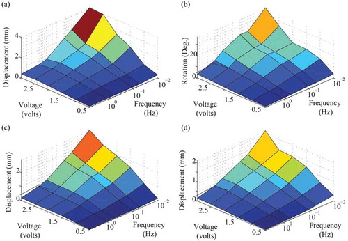
As can be seen, the amplitude of the response of the 3D-printed actuators continues to increase as the square-wave signals are slowed to 0.01 Hz, implying the time response is as slow as 100 seconds or more. Therefore, 3D printing thinner custom-shaped IPMCs will likely achieve faster response times and greater deflections.
2.5. Motion control
The actuation behavior of IPMCs exhibit several effects that limit their performance. First of all, IPMCs can exhibit back-relaxation, as shown in . In response to a step input, some IPMC actuators will initially deflect forward and will then drift backwards [Citation97]. This behavior prevents an IPMC from holding a position and distorts its tracking response to low frequency signals. So a way of mitigating this effect or compensating for it is needed for precision control of IPMC systems. Additionally, precise control of IPMC-based systems requires position and/or force feed-back as well as models of the electromechanical dynamics of IPMCs. So strategies of integrating IPMCs with sensors are needed as well as reliable models. Finally, IPMCs are sensitive to environmental conditions and exhibit low repeatability even in controlled conditions. So control strategies are needed that can adapt to changing dynamics or guarantee satisfactory response in spite of changing dynamics.
Figure 9. Successive step responses of the tip displacement of a cantilevered IPMC actuator exhibiting back-relaxation and non-repeatability. In response to a step input, a cantilevered IPMC actuator initially rises and then falls back past its initial position. A subsequent test on the same system under the same conditions also exhibits back-relaxation but the response is different than the response elicited in the first test. Figure reprinted with permission from [Citation42].
![Figure 9. Successive step responses of the tip displacement of a cantilevered IPMC actuator exhibiting back-relaxation and non-repeatability. In response to a step input, a cantilevered IPMC actuator initially rises and then falls back past its initial position. A subsequent test on the same system under the same conditions also exhibits back-relaxation but the response is different than the response elicited in the first test. Figure reprinted with permission from [Citation42].](/cms/asset/36cf8fdd-7476-4a42-91b2-a84f019c9443/tsnm_a_1438534_f0009_c.jpg)
2.5.1. Addressing back-relaxation in IPMCs
One way to address IPMC back-relaxation is to use different IPMC materials and manufacturing methods than traditional fabrication of Nafion based IPMCs. For instance, IPMCs fabricated using Flemion or some IPMCs fabricated using sulfonated polystyrene exhibit very little or no back-relaxation [Citation27,Citation73]. Additionally, back-relaxation can be reduced through use of different solvents and neutralizing counterions [Citation98]. Additionally, work to improve the surface morphology of platinum electrodes by depositing a thin layer of palladium particles on the surface of the membrane prior to proceeding with the plating process also had the effect of eliminating back-relaxation [Citation84]. Additional materials and methods for fabricating IPMCs that exhibit little or no back-relaxation might become available as IPMC back-relaxation becomes better understood [Citation99,Citation100].
Steps to mitigate IPMC back-relaxation through adjusting the methods and materials used in fabrication are attractive because they improve the performance of the actuator itself. However, back-relaxation or other related effects may not be completely eliminated through this approach. A simple strategy for compensating for remaining back-relaxation is the use of feedback control, such as simple proportional-integral-derivative (PID) control [Citation66]. However, this approach could lead to excessively large control effort if back-relaxation is severe, and thus the high input signals can damage the actuator.
Another approach to addressing IPMC back-relaxation involves sectoring an IPMC into opposed sectors [Citation43], as shown in . In this use of an IPMC actuator, the response of one sector is used to augment the response of the opposed sector. The resulting tip displacement is a combination of the responses of the two sectors. This allows the maintenance of the IPMC tip position in spite of pronounced back-relaxation. However, this approach adds complexity to the design and fabrication of the IPMC actuator and sacrifices efficiency since two actuators are intentionally operated in opposition.
Figure 10. Use of sectored ionic polymer-metal composite (IPMC) to address back-relaxation: (a) conceptual design of sectored IPMC actuator, (b) illustration of the cancellation effect using the responses of the independent sectors. Figure reprinted with permission from [Citation43].
![Figure 10. Use of sectored ionic polymer-metal composite (IPMC) to address back-relaxation: (a) conceptual design of sectored IPMC actuator, (b) illustration of the cancellation effect using the responses of the independent sectors. Figure reprinted with permission from [Citation43].](/cms/asset/d874b13f-fc25-4c0d-b3da-1326b2f167ac/tsnm_a_1438534_f0010_c.jpg)
2.5.2. Sensing for feedback control of IPMCs
Motion control of IPMCs is often facilitated by the use of extrinsic sensors like cameras or laser displacement sensors, when practical. The IPMC sensing response can be used for self-sensing, but this approach may be challenging, because the inherent IPMC sensing response is low-voltage, dynamic and will be overwhelmed by cross-talk [Citation101,Citation102]. The low-voltage and dynamic quality of the sensing can be addressed using a charge amplifier, but cross-talk would have to be dealt with. So instead, some self-sensing strategies use the change in resistance across the electrodes of an IPMC [Citation102], as illustrated in ). The advantages of this approach are that the sensor response is static. Approaches to self-sensing can use the same electrodes used for actuation, as shown in ) or use separate electrodes as shown in ). The challenge of using the same electrodes is filtering out the effect of the actuation signal. One strategy is to take the difference between voltage drops across constrained and unconstrained regions of the IPMC electrode, as shown in ). Another is to add a high-frequency component to the actuation signal as shown in ) and extract the sensing response by filtering out the low-frequency component. Alternatively, if separate electrodes are used, an intermediate segment can also be added to shield the sensor segments, as shown in ) and (e). An advantage of the use of the IPMC electrode itself as the sensor is that it is compact and relatively simple to manufacture. A disadvantage of the approach is that the surface resistance of the electrodes may be more prone to changing with wear or in response to different environmental conditions [Citation101].
Figure 11. Self-sensing IPMC actuator designs: (a) change in electrode surface resistance (R1 and R2 vs. R1′ and R2′) due to strain from IPMC bending, (b) self-sensing IPMC design using difference in voltage drop along electrodes of the constrained sections of IPMC and electrodes along the unconstrained sections of the IPMC ((UM1 – UF1) − (UM2 – UF2)), (c) IPMC sectored into three sectors consisting of actuator, shielding and sensor regions, (d) input signal into IPMC actuator in Fig. (b) consisting of actuation signal with high frequency component that can be utilized for sensing after filtering out low frequency component, (e) bridge configuration utilized with IPMC actuator in Fig. (c) for sensing. Figures (a-d) reprinted with permission from [Citation141]. Figure (e) reprinted with permission from [Citation101].
![Figure 11. Self-sensing IPMC actuator designs: (a) change in electrode surface resistance (R1 and R2 vs. R1′ and R2′) due to strain from IPMC bending, (b) self-sensing IPMC design using difference in voltage drop along electrodes of the constrained sections of IPMC and electrodes along the unconstrained sections of the IPMC ((UM1 – UF1) − (UM2 – UF2)), (c) IPMC sectored into three sectors consisting of actuator, shielding and sensor regions, (d) input signal into IPMC actuator in Fig. (b) consisting of actuation signal with high frequency component that can be utilized for sensing after filtering out low frequency component, (e) bridge configuration utilized with IPMC actuator in Fig. (c) for sensing. Figures (a-d) reprinted with permission from [Citation141]. Figure (e) reprinted with permission from [Citation101].](/cms/asset/28b654bb-2302-47bf-9cf8-95815a63ac29/tsnm_a_1438534_f0011_c.jpg)
An alternative to using the change of resistance across the electrodes, is to integrate an IPMC with a resistive sensor such as a strain gauge or nichrome wire [Citation104], as shown in ), or a piezoelectric sensor such as PVDF film [Citation101], as shown in ). Use of a resistive sensor requires incorporation into a simple voltage divider or Wheatstone bridge as shown in ). Use of the piezoelectric properties of PVDF film requires the use of a differential charge amplifier as shown in ). The advantages of the use of a secondary sensor material are that the sensor response is generally more accurate. The disadvantage is that it requires additional assembly steps and may stiffen the actuator [Citation104].
Figure 12. IPMC actuators integrated with resistive or piezoelectric sensors: (a1) cantilevered IPMC bending actuator integrated with a strain gauge and a tube-shaped IPMC actuator integrated with nichrome wire, (a2) Wheatstone bridge circuit for use with resistive sensor like a strain gauge or nichrome wire, (b2) cantilevered IPMC bending actuator integrated with insulation and two layers of PVDF film, and (b2) differential charge amplifier circuit for use with PVDF film sensors. Figures (a1) and (a2) taken with permission from [Citation222]. Figures (b1) and (b2) reprinted with permission from [Citation101].
![Figure 12. IPMC actuators integrated with resistive or piezoelectric sensors: (a1) cantilevered IPMC bending actuator integrated with a strain gauge and a tube-shaped IPMC actuator integrated with nichrome wire, (a2) Wheatstone bridge circuit for use with resistive sensor like a strain gauge or nichrome wire, (b2) cantilevered IPMC bending actuator integrated with insulation and two layers of PVDF film, and (b2) differential charge amplifier circuit for use with PVDF film sensors. Figures (a1) and (a2) taken with permission from [Citation222]. Figures (b1) and (b2) reprinted with permission from [Citation101].](/cms/asset/8f23ff38-46a9-4604-98ae-048670d10408/tsnm_a_1438534_f0012_c.jpg)
2.5.3. Modelling of IPMCs for motion control
One approach to controlling IPMC-based systems is to leverage models to drive an IPMC based on its anticipated response to an electric input. For control purposes, these models can be developed through empirical (for example see [Citation105]) or physics based methods (for example see [Citation106]), but should accurately reflect the dynamics of an IPMC over the intended operational range using a minimal number of parameters.
There are many reduced-order models of IPMCs with much of the variety stemming from different approaches to modelling the electrical dynamics [Citation107], as shown in . A comparison of various approaches to modelling the electrical dynamics is given in [Citation109], which is summarized here. These models are compared to a simple RC circuit model consisting of a resistor and capacitor in series, as shown in (a). One model adds a resistor in parallel to this RC circuit, to account for the resistance of the solid electrolyte [Citation110], as shown in (b). Another model consists of two parallel arrangements of a resistor and a capacitor connected in series with a bulk resistor [Citation111], as shown in (c). One model includes eight components as well as nonlinear diodes [Citation112], as shown in (d). Finally, another model simply includes a Warbug impedance element in an RC circuit to address low frequency behaviour [Citation109], as shown in (e).
Figure 13. Equivalent circuit models of IPMC electrical dynamics and comparison to experimentally measured impedance of an IPMC over a range of frequencies: (a) a resistor and capacitor in series, (b) a resistor and capacitor in series with a resistor added in parallel [Citation110], (c) two parallel arrangements of a resistor and a capacitor connected in series with a bulk resistor [Citation111], (d) model including eight components as well as nonlinear diodes [Citation112], (e) RC circuit with a Warburg impedance element [Citation109], (f) real part of the impedance of an IPMC compared to models, (g) imaginary part of the impedance of an IPMC compared to models. Figure adapted with permission from [Citation109].
![Figure 13. Equivalent circuit models of IPMC electrical dynamics and comparison to experimentally measured impedance of an IPMC over a range of frequencies: (a) a resistor and capacitor in series, (b) a resistor and capacitor in series with a resistor added in parallel [Citation110], (c) two parallel arrangements of a resistor and a capacitor connected in series with a bulk resistor [Citation111], (d) model including eight components as well as nonlinear diodes [Citation112], (e) RC circuit with a Warburg impedance element [Citation109], (f) real part of the impedance of an IPMC compared to models, (g) imaginary part of the impedance of an IPMC compared to models. Figure adapted with permission from [Citation109].](/cms/asset/0dee782d-ef2b-4b1a-972f-444a42c355b7/tsnm_a_1438534_f0013_c.jpg)
In [Citation109], impedance measurements of an IPMC was made over a range of frequencies and a least square error method was employed to fit the models in to the real and imaginary parts of the impedance data as well as possible. The real part of the measured impedance of an IPMC is compared to the models in (f) and the imaginary part of the measured impedance of an IPMC is compared to the models in (g). The R-squared values of models (a) through (e) are 0.5023, 0.8166, 0.8166, 0.9429 and 0.9868 respectively [Citation109]. The model incorporating a Warburg impedance element simply and accurately models IPMC electrical dynamics at both low and high frequencies.
Having modelled the electrical dynamics of an IPMC, it’s common to approximate material stress as proportional to charge density, though this may not capture back-relaxation [Citation43].
2.5.4. Feedforward and feedback control of IPMCs
Control of dynamic systems like IPMCs, can be broken into three approaches as illustrated in . Feedforward control techniques such as inverse dynamics control determines the requisite input (uff) to produce the desired output (yd), as shown in ). Feedback control of an IPMC uses negative feedback to determine a control effort based on the error (e) between the desired output (yd) and the actual output (y) of a system, as shown in ). Finally, many practical control techniques employ a combination of feedforward and feedback control, as shown in ). Effective feedforward control requires accurate models and often this technique lacks robustness. In the case of controlling IPMCs, perfect control can’t be guaranteed even in the absence of disturbances, because of IPMCs’ sensitivity to environmental conditions and low repeatability. Feedback control therefore needs to be implemented to compensate for these effects. Proportional-integral (PI) and proportional-integral-derivative (PID) control have been implemented as stand-alone controllers [Citation113,Citation114] and also have been implemented along with model-based feedforward control [Citation114].
Figure 14. Methods for controlling IPMCs: model-based feedforward control of an IPMC that functions by determining the requisite input (uff) to produce the desired output (yd), (b) feedback control of an IPMC that uses sensor information to determine a control effort based on the error (e) between the desired output (yd) and the actual output (y), and (c) integrated feedforward/feedback control that uses feedback control to correct for disturbances and modelling error. Figure taken with permission from [Citation222].
![Figure 14. Methods for controlling IPMCs: model-based feedforward control of an IPMC that functions by determining the requisite input (uff) to produce the desired output (yd), (b) feedback control of an IPMC that uses sensor information to determine a control effort based on the error (e) between the desired output (yd) and the actual output (y), and (c) integrated feedforward/feedback control that uses feedback control to correct for disturbances and modelling error. Figure taken with permission from [Citation222].](/cms/asset/38e95d53-188d-4542-a6d3-d780080308dc/tsnm_a_1438534_f0014_b.gif)
However, because of the variable dynamics of IPMCs, the performance of a conventional PID controller can vary widely over the lifetime of the IPMC. For this reason, more sophisticated feedback control techniques such as adaptive control and robust control are sometimes employed.
To achieve high precision control in spite of variable dynamics, another approach is to have control parameters that can be adjusted on the fly to adapt to changing dynamics. Model reference adaptive control (MRAC) is one of these adaptive control strategies. Ideally, it operates by compensating for modelling error to make the system behave like the model, thus maintaining behavioral performance in spite of changing dynamics [Citation115,Citation116]. The adaptation law is based on some form of optimization. For instance, control parameters can be adapted based on gradient descent method [Citation116] or with use of a computational method such as a genetic algorithm [Citation115]. Adaptive control can also be accomplished without reference to a model but rather by optimizing controller parameters directly, as has been done using iterative feedback tuning (IFT) [Citation117,Citation118]. Since IFT does not use a model, it has the advantage that it can readjust to any change in system dynamics or input. By comparison, MRACs perform poorly if the actual system dynamics vary widely from the reference model.
In other applications, adapting to changing IPMC dynamics may not be so much the concern as guaranteeing robust performance in spite of changing dynamics. These robust control approaches proceed by first obtaining a nominal model of the IPMC dynamics as well as the range of its variability. A frequency weighted controller is designed that guarantees tracking error and voltage input will not exceed specified maximums so long as disturbances and sensor noise remain within specified bounds [Citation42,Citation119]. The advantages of these techniques are performance and safety guarantees, which may be essential for some applications. The disadvantages are that it requires high-order control laws and that performance may be suboptimal for any given system dynamics and input.
In addition to these approaches, it’s noteworthy that direct control of current can mitigate some time varying effects in IPMCs. This is an attractive approach because the current input to an IPMC can much more reliably be sensed and controlled in real-time than an IPMC’s tip position or curvature. The downside is that it is not a complete solution, could lead to excessive voltage inputs and requires more complicated hardware than voltage control [Citation42].
3. Conjugated polymer and ionic gel actuators
Conductive polymer and ionic gel actuators are ionic electroactive polymers that transport solvated ionic species to produce deformation, like IPMCs. Since conductive polymers and ionic gels are often employed together to create composite actuators, this section will discuss conductive polymers and ionic gels (ionogel) in isolation as well as composited together. This section will first discuss the composition, mechanics, and advantages of conductive polymers, and ionogels. It will then address various applications of them. It will go on to discuss conventional and freeform fabrication of these materials and conclude by addressing motion control of them.
3.1. Composition, mechanics and advantages
3.1.1. Conductive polymers
Conductive polymers are organic semiconductors, such as polypyrrole (PPy), poly(3,4-ethylenedioxythiophene) polystyrene sulfonate (PEDOT:PSS) and polyaniline (PANI) with alternating single and double bonds as illustrated in . Conductive polymers are also called conjugated polymers in reference to this structure. Application of a sufficient positive potential to such a conjugated polymer, will remove electrons leaving positive charge carriers, making the material p-doped [Citation120]. Negatively charged anions are incorporated into the polymer to neutralize it [Citation120]. This process can then be reversed, by application of a sufficiently negative potential.
Figure 15. Composition of conductive polymers illustrating their conjugated structure of alternating single and double bonds and the reduced and oxidized states: (a) undoped conjugated polymer (reduced), (b) doped conjugated polymer (oxidized). Figure reprinted with permission from [Citation120].
![Figure 15. Composition of conductive polymers illustrating their conjugated structure of alternating single and double bonds and the reduced and oxidized states: (a) undoped conjugated polymer (reduced), (b) doped conjugated polymer (oxidized). Figure reprinted with permission from [Citation120].](/cms/asset/e1b167b9-0269-40a3-86c1-7709432d13e9/tsnm_a_1438534_f0015_b.gif)
The alternation between the reduced and oxidized states of conductive polymers gives conductive polymers their size changing ability. The volume of the conductive polymer changes in response to the change in oxidation level. This is driven by multiple mechanisms, the most dominant of which is absorption and expulsion of ionic liquids [Citation120]. For instance, some conductive polymers incorporate anions when oxidized (causing them to expand) and expel ions when reduced (causing them to contract).
Conductive polymers have the benefit of actuation from low operation voltages, light weight, good flexibility, bio-compatibility, negligible self-discharge, high force-generation capabilities, high energy density per cycle and that they can be manufactured on the nano- and micro-scale [Citation121]. Moreover, strain in some conductive polymers is roughly proportional to oxidation level [Citation120], which simplifies motion control of them. However, conductive polymers also suffer from a limited cycle rate, limited cycle life, require a reservoir of electrolytic solution, and have high oxygen sensitivity. Like IPMCs, they also exhibit environmental sensitivity and low repeatability [Citation122,Citation123].
3.2. Ionic gels
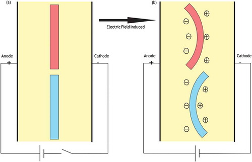
Ionic gels or ionogels are ion-conducting polymer electrolytes similar to ion-exchange membranes employed in IPMCs. They consist of a charged polymer network with macro-ions fixed on the polymer chains and neutralizing micro-counterions in solution [Citation124]. However, unlike ion-exchange membranes, ionic gels are polymerized mixtures of vinyl monomers in ionic liquids (molten salts, such as 1-ethyl-3-methyl imidazolium bis(trifluoromethane sulfonyl)imide) and have a swollen weight of up to 2000% their dry weight [Citation124]. Therefore, ionogels are much softer and much more deformable than a typical ion-exchange membrane. As with IPMCs, the forces at work in ionic gel actuators include rubber elasticity, counter-ion osmotic pressure, and electrophoretic interactions [Citation1]. In response to an applied electric field, ionogels will transport solvated counter-ions causing an asymmetric bulk strain (and thus a bending) due to a difference in the concentration of the neutralizing counterions [Citation1], as shown in . Unlike an IPMC however, significant polymer-solvent viscous interactions counter balance the elastic forces. The counter-ion osmotic pressure and electrophoretic interactions change the equilibrium point of the ionic gel actuator when an electric field is applied [Citation1]. Consequently, ionic gels do not return to their previous shape when that electric field is removed.
Figure 16. Demonstration of the difference in bending direction of ionic gels with an anionic and cationic polymer network: (a) no electric field is applied and no bending is exhibited, (b) an electric field is applied causing the cationic gel (blue) to bend toward the anode and the anionic gel (red) to bend toward the cathode.
Ionogels have the advantages of large volume changes and deformation and low activation voltages [Citation7,Citation124,Citation125]. The use of ionic liquid (IL) in the polyelectrolyte also increases the voltage that can be applied without exceeding the decomposition potential. Additionally, the low volatility and hydrophobicity of ionic liquids slows their evaporation in air and diffusion in aqueous environments [Citation126], both of which are challenges for conventional water based IPMCs.
3.2.1. Conductive polymer ionogel composites
Conductive polymers and ionogels are often applied in multi-layer composites with other materials. For instance, a bending actuator can be fabricated by compositing a conductive polymer with a metal electrode [Citation120]. A tri-layer bending actuator can also be produced by sandwiching a polyelectrolyte (such as an ion-exchange membrane or an ionogel) between two conductive polymers, as shown in ). In such an arrangement the polyelectrolyte layer acts as an exchange layer and reservoir between the conducting polymer layers [Citation120,Citation127,Citation128]. In this setup, the conductive polymer on the anodic side is oxidized, while the conductive polymer on the cathodic side is reduced. As the anode layer absorbs anions and expands, the cathode layer releases anions and contracts, producing a bending motion in the actuator. In this arrangement the conductive polymers are both anion exchangers. Alternatively, a tri-layer actuator design can also be used to produce linear strain when one conductive polymer film is a cation-exchanger and the other is an anion-exchanger as shown in . The composite of a polyelectolyte and a conductive polymer is thus an elegant way to address conductive polymers’ need for a reservoir and the polyelectrolyte's need for electrodes.
Figure 17. Illustration of a tri-layer conjugated polymer actuator demonstrating bending actuation (left) and linear actuation (right). Figure reprinted with permission from [Citation225].
![Figure 17. Illustration of a tri-layer conjugated polymer actuator demonstrating bending actuation (left) and linear actuation (right). Figure reprinted with permission from [Citation225].](/cms/asset/88eb158e-3306-410e-87d5-a9a359c24392/tsnm_a_1438534_f0017_c.jpg)
3.3. Applications
The large work density, low voltage requirements, operation in aqueous environments, the linear relation of strain to charge, and large electrically controllable shape change ability make conductive polymers especially attractive for highly dynamic systems like robots. For instance, cell handling systems have been fabricated using conductive polymers [Citation2], as shown in ) as well as microscopic lids and active hinges [Citation3], as shown in ).
Figure 18. Applications of conductive polymerbi-layer actuators: (a) robot for handling microscopic glass beads, (b) cell clinic with an active hinge. Figure (a) reprinted with permission from [Citation2]. Figure (b) reprinted with permission from [Citation3].
![Figure 18. Applications of conductive polymerbi-layer actuators: (a) robot for handling microscopic glass beads, (b) cell clinic with an active hinge. Figure (a) reprinted with permission from [Citation2]. Figure (b) reprinted with permission from [Citation3].](/cms/asset/e3453280-1e6d-4a33-8aca-3ffb48a3b29b/tsnm_a_1438534_f0018_c.jpg)
Because of their large volumetric strains, position keeping ability and soft compliant bodies, ionogels have been used in a variety of biomimetic applications, as shown in . For instance, a walking gel robot for use in natural saline environments was fabricated out of anionic acrylamide (AAm)/sodium acrylate (NaAc) copolymer and cationic acrylamide/ quaternized dimethylaminoethyl methacrylate (DMAEMA-Q) copolymer for its respective legs as shown in ) A variety of crawling and swimming robots have been fabricated using similar materials [Citation1,Citation5,Citation7] as shown in ). Ionic gels also have been employed in grippers, and worm-like robots [Citation1]. Most of these applications made use of an electrolytic environment and the application of electric field by extrinsic electrodes.
Figure 19. Applications of ionic gels: (a) walking robot fabricated by laser cutting prefabricated ionic gels, (b) multi-stimuli responsive micro-robots fabricated using a microfluidic device and photo-lithographic techniques. Figure (a) reprinted with permission from [Citation7]. Figure (b) reprinted with permission from [Citation5].
![Figure 19. Applications of ionic gels: (a) walking robot fabricated by laser cutting prefabricated ionic gels, (b) multi-stimuli responsive micro-robots fabricated using a microfluidic device and photo-lithographic techniques. Figure (a) reprinted with permission from [Citation7]. Figure (b) reprinted with permission from [Citation5].](/cms/asset/0082f206-1f86-47b9-a225-dee3ad9e722e/tsnm_a_1438534_f0019_c.jpg)
3.4. Conventional manufacturing and materials
3.4.1. Fabricating conjugated polymers
As shown in , conjugated polymer films can be deposited directly from a solution, from a precursor, by chemical-vapor deposition, or electro-polymerization depending on the material [Citation129]. Polyaniline (PANI) films can be deposited by spin-coating a dispersion of it as shown in ). Some materials cannot be dissolved but have precursor polymers or monomers that can be. In which case these are spin coated and then cured, as shown in ). An example of this approach is spin coating pyrrole- 2-carboxylic acid (the precursor to PPy) followed by curing it by heating [Citation129]. If these approaches cannot be applied, then electro-polymerization is the most common technique to fall back on, as shown in ). The downside of electro-polymerization is that it requires an electrode, whereas the other methods can be used to deposit conductive polymers on any free surface [Citation129].
Figure 20. Deposition of conjugated polymer film: (a) from spin coating a dispersion of the conjugated polymer (b) spin coating a precursor of the conjugated polymer, followed by curing, (c) vapor deposition, (d) electro-polymerization. Figure reprinted with permission from [Citation129].
![Figure 20. Deposition of conjugated polymer film: (a) from spin coating a dispersion of the conjugated polymer (b) spin coating a precursor of the conjugated polymer, followed by curing, (c) vapor deposition, (d) electro-polymerization. Figure reprinted with permission from [Citation129].](/cms/asset/a4715c3b-2797-49bf-bc9d-fe746b76d100/tsnm_a_1438534_f0020_b.gif)
Electro-polymerization can be conducted with a three-electrode potentiostat, where the conjugated polymer will be deposited on the working electrode. Refer to [Citation129] for more information.
In addition to these techniques, it is also possible to melt process some conjugated polymers such as PANI, and blends of conjugated polymers if appropriate doping agents are used, but these methods have not been explored especially for use of conjugated polymer as actuators [Citation130].
3.4.2. Fabricating ionogels
There are a variety of approaches to fabricating ionic gels. As illustrated in , one approach is through in situ polymerization of vinyl monomers dissolved in an ionic liquid, such as 1-ethyl-3-methyl imidazolium bis(trifluoromethane sulfonyl)imide (EMITFSI) [Citation131].
Figure 21. In situ polymerization of vinyl monomers dissolved in an ionic liquid to produce an ionic gel. Figure reprinted with permission from [Citation131] (Copyright 2009 American Chemical Society).
![Figure 21. In situ polymerization of vinyl monomers dissolved in an ionic liquid to produce an ionic gel. Figure reprinted with permission from [Citation131] (Copyright 2009 American Chemical Society).](/cms/asset/19c0faaa-9d8c-4427-9bdd-11f744f3d019/tsnm_a_1438534_f0021_c.jpg)
This approach works well with poly(methylmethacrylate)s (PMMA) because of the high compatibility of PMMA with imidazolium salts such as EMITFSI [Citation28]. This technique has also been employed by adding Hydroxyethylmethacrylate (HEMA) with 1%wt 2,2-diethoxyacetophenone (DEAP) to a suspension of Zirconium dioxide (ZrO2) in 1-butyl-3-methylimidazolium tetrafluoroborate (BMIMBF4). This mixture was then polymerized by irradiating it using ultraviolet (UV) light without an initiator as another recent example [Citation132].
Alternatively, ionogels can be fabricated by simply swelling a polymer with an ionic liquid [Citation28]. For instance, a study was conducted on the swelling of Nafion and other polymers with imidazolium salts 1-n-butyl-3-methylimidazolium Tetrafluoroborate (C4mim)(BF4) salts and other ionic liquids [Citation133].
3.4.3. Fabricating multi-layer composites
In order to operate outside of an electrolytic environment, ionogels have to be composited with additional layers that both serve as electrodes and that exchange ionic liquid with the ionogel. For this reason, actuators have been fabricated using composites of conjugated polymers and permeable membranes. In order to get good adhesion between the membrane layer and the conjugated polymers, one strategy is to plate a porous membrane such as PVDF, electrically deposit the conjugated polymer on the plated PVDF and then infuse the membrane with an ionic liquid. For instance, one composite was prepared by electrochemically depositing polypyrrole on a platinized PVDF membrane. The composite was then immersed in 1-ethyl-3-methylimidazolium bis(trifluoromethyl sulfonyl) amide (EMIm TFSA) and methyl methacrylate monomers. An initiator and cross-linker were added to polymerize the absorbed mixture, after the mixture had absorbed into the PVDF. Refer to [Citation134], for more information.
As alternatives to compositing ionic gels with conjugated polymers, more recent approaches to fabricating these multilayer composites employ carbon dispersed in ionic gels as electrode layers. These materials are electrically conductive like conjugated polymers and expand as they absorb ions from the more concentrated ionic gel layer. One significant example employed ground single wall nanotubes (SWNT)s dispersed in an ionogel, refered to as ‘bucky- gel’ [Citation135]. In an ionogel consisting of poly(vinylidene fluoride-co-hexafluoropropylene) (PVdF(HFP) and 4-methyl-2-pentanone (MP) as the polymer and 1-butyl-3-methylimidazolium tetrafluoroborate (BMIBF4) as the ionic liquid, the addition of SWNTs to the mixture creates electrode layers that the pristine ionogel can be sandwiched between [Citation135], as shown in . The ‘bucky-gel’ mixture can be ball milled to exfoliate the heavily entangled bundles of SWNTs to more evenly disperse them in the gel [Citation136]. This composite actuator can be fabricated through layer-by-layer casting, followed by hot pressing. Refer to [Citation135,Citation136] for details.
Figure 22. Composition of a ‘bucky-gel’ actuator: (a) schematic of layered structure of bucky-gel actuator consisting of a ionic gel with single wall nanotubes (SMNT)s as the electrode layer and a pristine ionic gel as the polyelectrolyte layer sandwiched between the electrode layers, (b) chemical formula of the ionic liquid, 1-butyl-3-methylimidazolium tetrafluoroborate (BMIBF4), and the polymer, poly(vinylidene fluoride-co-hexafluoropropylene) (PVdF(HFP). Figure reprinted with permission from [Citation136].
![Figure 22. Composition of a ‘bucky-gel’ actuator: (a) schematic of layered structure of bucky-gel actuator consisting of a ionic gel with single wall nanotubes (SMNT)s as the electrode layer and a pristine ionic gel as the polyelectrolyte layer sandwiched between the electrode layers, (b) chemical formula of the ionic liquid, 1-butyl-3-methylimidazolium tetrafluoroborate (BMIBF4), and the polymer, poly(vinylidene fluoride-co-hexafluoropropylene) (PVdF(HFP). Figure reprinted with permission from [Citation136].](/cms/asset/88fb8f5f-6250-401e-876c-88db246401df/tsnm_a_1438534_f0022_c.jpg)
Another recent method employs activated carbon layers. In this approach, hydroxyethyl methacrylate (HEMA) is added to a mixture of 1-butyl-3- methylimidazolium tetrafluoroborate (BMIMBF4) and ZrO2-nanoparticles and cured with UV light. This ionic gel results in an ionic liquid film on the surface that can be used to adhere the activated carbon layers to it. The active carbon layers are then coated with a gold foil layer. Refer to [Citation132] for more information.
3.5. Free-from fabrication techniques
There are multiple approaches to patterning material using micromachining techniques, suited for various conjugated polymers [Citation129], as illustrated in . Some polymers, like poly(alkylthiophenes), can be patterned by use of light and a mask, as shown in ). Alternatively, the electrode layer can be deposited first and then employed to control the deposition of the conjugated polymer, as shown in ). Another approach to is to coat the wafer in a metal film followed by positive resist. The areas in which the polymer is wanted are exposed using a positive mask. The polymer is deposited on the bare metal, following which the photo resist is removed, as shown in ). Another approach is rather than selectively deposit the conjugated polymer is to selectively remove the conjugated polymer after it is deposited, using techniques such as reactive ion etching (RIE), as shown in ). If the material between the desired regions does not need to be removed but rather simply made electrochemically inert then this can also be done by selective exposure, as shown in ). For instance, PEDOT can be made non-conductive by exposure to Cr etchant. Lastly, the inverse of this method is to selectively dope areas either by exposure to a gas or acid, as shown in ). Refer to [Citation129] for more details on these techniques.
Figure 23. Micromachining methods of patterning conjugated polymers and electrodes: (a) direct patterning of conjugated polymer using UV light and a mask, (b) deposition of conjugated polymer onto selectively patterned electrodes, (c) selective deposition of conjugated polymer using etched photo resist, (d) etching of deposited conjugated polymer layer after being deposited, (e) selectively removing conductivity of conjugated polymer, (f) selective doping of conjugated polymer. Figure reprinted with permission from [Citation129].
![Figure 23. Micromachining methods of patterning conjugated polymers and electrodes: (a) direct patterning of conjugated polymer using UV light and a mask, (b) deposition of conjugated polymer onto selectively patterned electrodes, (c) selective deposition of conjugated polymer using etched photo resist, (d) etching of deposited conjugated polymer layer after being deposited, (e) selectively removing conductivity of conjugated polymer, (f) selective doping of conjugated polymer. Figure reprinted with permission from [Citation129].](/cms/asset/27128fa0-7072-4f3c-9d10-54c53e426824/tsnm_a_1438534_f0023_b.gif)
Finally, in addition to these processes it will often be desired to create layered structures with actuators capable of out-of-plane motion. This can be done by use of a sacrificial layer which is removed after the conjugated polymer is deposited on top of it, as shown in ) or using a differential adhesion method where the conjugated polymer simply doesn’t adhere to part of the underlying substrate [Citation3,Citation129], as shown in ).
Figure 24. Micromachining methods of creating out of plane conjugated polymer bending actuators: (a) use of a sacrificial layer (b) differential adhesion method. Figure reprinted with permission from [Citation129].
![Figure 24. Micromachining methods of creating out of plane conjugated polymer bending actuators: (a) use of a sacrificial layer (b) differential adhesion method. Figure reprinted with permission from [Citation129].](/cms/asset/011f3cf4-aa4b-4796-bdf4-6034aa2a338e/tsnm_a_1438534_f0024_b.gif)
The in situ polymerization method for fabrication of ionogels can be applied using lithographic methods with microfluidic devices to create complex ionogel robots with multiple gel types, as shown in ). By this approach, pre-polymer solution is introduced into the microfluidic device using a syringe pump. A photo- mask is then used with UV light to selectively cure regions in the microfluidic device. The pre-polymer solution is then washed out and replaced by the next pre- polymer solution in the sequence, until the robot is complete. Alternatively, device components can be laser cut from prefabricated ionogels, as shown in ).
Figure 25. Freeform fabrication of ionic gel robots and devices: (a1) use of a microfluidic device and photo-polymerization using an ultraviolet (UV) light and photo-mask to selectively cure solutions of monomers and ionic liquids to sequentially fabricate miniature ionogels, (a2) a biomimetic aqua-bot fabricated using this technique, (b1) laser-cutting device components out of prefabricated ionogel material, (b2) a walking robot fabricated using this laser cutting technique. Figures (a1) and (a2) adapted with permission from [Citation5]. Figures (b1) and (b2) adapted with permission from [Citation7].
![Figure 25. Freeform fabrication of ionic gel robots and devices: (a1) use of a microfluidic device and photo-polymerization using an ultraviolet (UV) light and photo-mask to selectively cure solutions of monomers and ionic liquids to sequentially fabricate miniature ionogels, (a2) a biomimetic aqua-bot fabricated using this technique, (b1) laser-cutting device components out of prefabricated ionogel material, (b2) a walking robot fabricated using this laser cutting technique. Figures (a1) and (a2) adapted with permission from [Citation5]. Figures (b1) and (b2) adapted with permission from [Citation7].](/cms/asset/53aeb933-5e77-46a0-98ca-3197cb598e91/tsnm_a_1438534_f0025_c.jpg)
In addition to these methods an attempt was made at automating the fabrication of bucky-gel actuators, using a gel casting 3D printer. See [Citation137] for details.
3.6. Motion control
Like with IPMCs, motion control of layered actuators based on conjugated polymers and ionic gels requires the use of dynamics models and sensors to make use of force and/or position feedback. Also like IPMCs, conjugated polymer actuators’ dynamics vary over time, especially because of creep [Citation138]. Unlike IPMCs however, conjugated polymer actuators do not exhibit a back-relaxation effect. In layered actuators with single moving ions, the strain is directly proportional to the oxidation level over a large range of voltage inputs [Citation120]. As with IPMCs, it is common to model an electromechanical eigenstress as proportional to charge density.
Conjugated polymers produce a dynamic sub-millivolt scale electric signal in response to being mechanically deflected [Citation139]. A proposed approach to utilizing the sensor response of conjugated polymer actuator, involves etching a groove in the conjugated polymer actuator [Citation140], as shown in ) to electrically isolate a region of the material for use as a sensor. This then is proposed for use in feedback control, by identifying and inverting the sensor dynamics, F(s) [Citation140], as shown in ). However, the proposed approach is not demonstrated. Since the actuation signal is orders of magnitude larger than the sensor signal that is produced, cross-talk may make the approach infeasible. Possible solutions to self-sensing may, however leverage other strategies that have been employed for use with IPMCs such as integration with a secondary sensor device, such as a strain gauge, or perhaps even use of the change in resistance across the electrode [Citation141].
Figure 26. Proposed self-sensing feedback control of a tri-layer polymer bending actuator: (a) schematic of tri-layer polymer bending actuator with a groove cut in the conjugated polymer that acts as the electrode to electrically isolate the actuator from the sensor region, (b) proposed control method utilizing the inverse dynamics of the sensor. Figure reprinted with permission from [Citation140].
![Figure 26. Proposed self-sensing feedback control of a tri-layer polymer bending actuator: (a) schematic of tri-layer polymer bending actuator with a groove cut in the conjugated polymer that acts as the electrode to electrically isolate the actuator from the sensor region, (b) proposed control method utilizing the inverse dynamics of the sensor. Figure reprinted with permission from [Citation140].](/cms/asset/5b436fdd-2f9b-4bc5-880d-fbd3a4ff3cd2/tsnm_a_1438534_f0026_c.jpg)
As with IPMCs, feedforward control is utilized with the multi-layer conjugated polymer actuators, but some form of feedback control is needed to compensate for disturbances and variable dynamics [Citation138]. Approaches that have been applied specifically to multi-layer conjugated polymer actuators include a self-tuning regulator [Citation142] as well as an adaptive neural fuzzy inference system (ANFIS) controller [Citation143]. However, approaches that have been applied to IPMCs are also applicable to multi-layer conjugated polymer actuators.
4. Shape memory polymers
SMPs are stimuli responsive materials that can be ‘frozen’ in a deformed shaped generally by the deprivation of a stimuli, such as heat. The undeformed shape can then be restored by reapplying that stimuli. SMPs are thus distinct from other kinds of active materials in that stimuli is used to ‘program’ and release a deformed shape rather than to directly cause a deformation. Consequently, SMPs are generally ‘one-way’ actuators or irreversible (i.e. the deformed shape cannot be restored without mechanical loading) [Citation144]. However, there are some notable ‘two-way’ SMPs and composites which utilize various stimuli to achieve reversible shape changes and actuation without manual deformation [Citation145–Citation147].
This section will begin by addressing the composition, mechanics and advantages of SMPs, followed by applications. This section will then discuss conventional manufacturing methods and automated and freeform adaptations of these manufacturing methods, and it will conclude by addressing motion control of SMPs.
4.1. Physics and actuation mechanics
Shape memory polymers contain stimuli responsive molecular mechanisms (commonly referred to as ‘switches’) that can be used to ‘freeze’ the polymer in a deformed shape [Citation144]. As an example, a thermally activated SMP can be ‘frozen’ in place, by mechanically deforming and then cooling it, as shown in . When the SMP is heated, the thermal responsive ‘switches’ will release allowing elastic forces to restore the materials undeformed shape [Citation148,Citation149]. These switches can consist of reversible molecular cross-links, supramolecular association/disassociation, melt transition, glass transition, liquid crystal anisotropic/isotropic transition, or covalent bonds [Citation148,Citation149] and may be responsive to heat, light and/or chemicals.
Figure 27. Cycle of ‘programming’ a thermal active SMP with a deformed shape and then restoring its undeformed shape through the following steps: (1) straining the material by applying a mechanical load, (2) cooling the material to ‘freeze’ in the deformed shape, (3) unloading the material, and finally (4) heating the material to restore its undeformed shape. Figure adapted with permission from [Citation226].
![Figure 27. Cycle of ‘programming’ a thermal active SMP with a deformed shape and then restoring its undeformed shape through the following steps: (1) straining the material by applying a mechanical load, (2) cooling the material to ‘freeze’ in the deformed shape, (3) unloading the material, and finally (4) heating the material to restore its undeformed shape. Figure adapted with permission from [Citation226].](/cms/asset/6ffb7975-9e83-4894-b6ae-08b1f78ce3eb/tsnm_a_1438534_f0027_c.jpg)
Thermal-sensitive SMPs have been the most common and widely used SMP actuator type. Thermal responsive SMPs are typically ‘frozen’ in a ‘programmed’ shape through vitrification or polymer crystallization [Citation150]. Deforming a polymer and lowering the temperature of the SMP below the glass transition temperature prevents the coordinated long range movements of polymer chains that would be required to restore the undeformed shape.
Two components are responsible for the light responsive shape memory effect (SME) on the molecular level: photo-reactive CA-type functional groups, such as cinnamylidene acetic acid (CAA) or cinnamic acid (CA) moieties, and cross-linking polymer-chain segments called netpoints that determine the permanent SMP shape. Light responsive SMPs have CAA or CA moieties incorporated in their polymer matrix that can create netpoint cross-links by irradiation with light of a suitable wavelength [Citation151], as shown in . Irradiating the SMP with light of a different wavelength breaks those cross-links allowing restoration of the undeformed shape [Citation152].
Figure 28. Photo-fixing and photo-cleaving of light responsive SMP through irradiation with light of appropriate wavelengths. The chromophores (open triangles) are covalently grafted onto the permanent polymer network, forming photoreversible cross-links (filled diamonds). The SMP is ‘programed’ with a deformed shaped by irradiating it with light of a suitable wavelength. The undeformed shape is restored by irradiating the polymer with light of a different wavelength. Figure reprinted with permission from [Citation163].
![Figure 28. Photo-fixing and photo-cleaving of light responsive SMP through irradiation with light of appropriate wavelengths. The chromophores (open triangles) are covalently grafted onto the permanent polymer network, forming photoreversible cross-links (filled diamonds). The SMP is ‘programed’ with a deformed shaped by irradiating it with light of a suitable wavelength. The undeformed shape is restored by irradiating the polymer with light of a different wavelength. Figure reprinted with permission from [Citation163].](/cms/asset/43a0164a-0373-4294-806a-c8e27f0a9519/tsnm_a_1438534_f0028_b.gif)
Light can also be used inderectly by heating a thermal-responsive SMP. SMPs actuated by such irradiative heating are not properly light-responsive SMPs because the molecular actuation mechanism common to light-responsive SMPs is not present. Moreover, light-triggered thermal-responsive SMPs will be much more strongly influenced by the ambient temperature and conductive heat transfer within the material [Citation151]. Chemo-responsive SMPs function based on the shifting of phase transition temperatures in response to being exposed to a substance like water [Citation153–Citation156]. A chemo-responsive SMP can be ‘programmed’ with a deformed shape, by drying out the material (raising the transition temperature) and then restored to its undeformedshape by hydrating it (lowering the transition temperature). A chemo responsive SMP capable of temperature-independent actuation was demonstrated by exposing the SMP to a solvent at room temperature [Citation156].
In general, advantages of SMPs are they can be programmed with large strains and exhibit high work densities. Additionally, there is a large range of materials that exhibit shape memory properties, so it is easy to tailor the SMP to specific applications (for instance, ones that require biocompatability). They are also easy to manufacture through a variety of fabrication techniques that can easily be adapted to automated and freeform fabrication methods. Also both light-responsive and thermal-responsive SMPs can be remotely actuated. Advantages of light-responsive SMPs specifically, are that by controlling the intensity of the light, the degree and speed of the actuation can be controlled. Additionally, by exposing only selected areas of the material, partial relaxation can be affected [Citation157].
A disadvantage of SMPs, in addition to generally being irreversible, is they tend to have a slow response. Most thermal active SMPs require at least 10 seconds to fully restore their undeformed shapes and some SMPs can take as long as several minutes.
4.2. Applications
The biomedical field is currently an attractive area for application of SMPs as active medical devices. Ambient body temperature can induce actuation in thermal SMPs while bodily fluids can actuate chemo-responsive SMPs. Because of their large irreversible deformations and durability, SMPs are especially suited for applications leveraging reconfigurable geometry. For instance, origami based robots make use of SMPs to fold up into their functional form after being fabricated from flat sheets. These have been employed to create various kinds of crawling robots [Citation158], as well as a, biodegradable robot for patching stomach wounds [Citation22]. There are also interesting ways to make operational use of SMPs responsiveness to stimuli like light and heat. For instance, biodegradable thermal SMPs can be used for suturing wounds, taking advantage of body heat to close the wound more tightly [Citation152]. In another application, porous SMP foam has been used as a self-fitting scaffold for treating Cranio-Maxillo facial bone defects [Citation159]. Additionally, light activated SMPs have been developed to be introduced into small arteries through a catheter for the capture and removal of blood clots [Citation160]. These applications of SMPs take advantage of the breadth of materials with shape memory properties to select materials that are non-toxic and non-mutagenic [Citation161]. There are also aerospace applications of SMPs that make use of large variations in light and heat in space [Citation32].
4.3. Conventional manufacturing and materials
A wide variety of conventional thermoplastics and thermosets can be used as SMPs and are thus manufactured through establish methods, such as, shape extrusion, injection molding, blowing, and laser ablation. Refer to [Citation162] for more manufacturing methods and further details. Many commercially available materials, like Nafion, exhibit shape memory properties without additional processing or treatments. However, in some cases secondary processes have to be applied to obtain a shape memory effect. For instance, CA and CAA moieties may need to be grafted into a polymer to obtain a light induced shape memory effect [Citation163], or methacrylate groups may need to be added to obtain a thermal shape memory effect [Citation164].
Composites of SMPs and other materials can also be fabricated to give the SMP special qualities. For instance, mixing carbon black with polyurethane results in a thermal-responsive, shape memory polymer that can be remotely actuated by being irradiated with visible light [Citation165]. A rapidly switchable water-sensitive SMP can be made with a cellulose/elastomer nano-composite by mixing thermoplastic polyurethane chips with treated cellulose whiskers [Citation156].
4.4. Freefrom fabrication techniques
There are a variety of automated and freeform fabrication techniques that have been developed for fabrication of SMPs, including fused filament fabrication, stereolithography, projection micro-stereolithography and PolyJet. Additionally, so called ‘4D printing’ or self-folding methods, where a desired 3D shape is obtained from the stimuli induced reconfiguration of material from its fabricated shape (commonly a two-dimensional sheet) is often employed with SMP material.
Fused filament fabrication has been used to 3D print light-triggered thermal-responsive SMP structures using a composite of polyurethane and carbon black, where the carbon black helps to absorb radiation from light sources [Citation165]. Stereolithographic (SLA) 3D printing was used to create thermal SMP actuators from a melted precursor of a methacrylated polycaprolactone (a semi-crystalline polymer) [Citation164]. Projection micro-stereolithography has been used with an automatic material exchange to create multi-material monolithic structures [Citation166], as shown in . Finally, Polyjet 3D printing (a multi-material 3D printing process consisting of ink-jet printing photo-curable resins and photo-polymerization) has been used to fabricate a three-layer composite of an elastomer, a hydrogel and a proprietary material (Grey60) that exhibits a shape memory effect [Citation147].
Figure 29. Projection micro-stereolithographic printing of a multi-material SMP: (a) Process of fabricating multi-material monolithic structure, (b) Photo-curable shape memory polymer network constructed using mono-functional monomer, Benzyl methacrylate (BMA) as linear chain builder (LCB), and multi-functional oligomers, Poly (ethylene glycol) dimethacrylate (PEGDMA), Bisphenol A ethoxylate dimethacrylate (BPA), and Di(ethylene glycol) dimethacrylate (DEGDMA) as crosslinkers. Figure adapted with permission from [Citation166].
![Figure 29. Projection micro-stereolithographic printing of a multi-material SMP: (a) Process of fabricating multi-material monolithic structure, (b) Photo-curable shape memory polymer network constructed using mono-functional monomer, Benzyl methacrylate (BMA) as linear chain builder (LCB), and multi-functional oligomers, Poly (ethylene glycol) dimethacrylate (PEGDMA), Bisphenol A ethoxylate dimethacrylate (BPA), and Di(ethylene glycol) dimethacrylate (DEGDMA) as crosslinkers. Figure adapted with permission from [Citation166].](/cms/asset/16d4a017-c92f-44f2-9b2f-a23bfdec337f/tsnm_a_1438534_f0029_c.jpg)
In addition to these 3D printing processes, 3D structures can also be produced by utilizing SMPs in multilayer self-folding structures as shown in . These structures are generally fabricated as unimorphs to generate bending in response to being heated [Citation167], as shown in . Complex patterns of folds (and possibly cuts) result in sophisticated 3D structures which can be integrated with additional elements such as magnets and motors for actuation [Citation168,Citation169]. Generally, fabrication involves first compositing the SMP material with adhesive and other materials. Then machining can be employed to create cuts and folding element patterns. This approach can be leveraged to create a variety of robots over a range of sizes.
Figure 30. Self-folding using SMPs: (a) fabrication of self-folding element consisting of PVC (SMP material), adhesive and supporting layers, (b) architecture and activation of self-folding element, (c) fold pattern of self-folding origami robot, (d) folded origami robot. Figure reprinted with permission from [Citation167].
![Figure 30. Self-folding using SMPs: (a) fabrication of self-folding element consisting of PVC (SMP material), adhesive and supporting layers, (b) architecture and activation of self-folding element, (c) fold pattern of self-folding origami robot, (d) folded origami robot. Figure reprinted with permission from [Citation167].](/cms/asset/8c457f71-8e49-4314-8bab-fb4f57342a3e/tsnm_a_1438534_f0030_c.jpg)
4.5. SMP motion control
Active areas of research affecting motion control of SMPs include extent of actuation [Citation165,Citation170,Citation171], sequencing in multi-actuator structures [Citation170,Citation171], reversibility [Citation1,Citation146,Citation149,Citation172], repeatability [Citation1,Citation157], number of possible 'programable' shapes [Citation157,Citation172], and controlling the range of stimuli SMPs are responsive to[Citation1,Citation149,Citation157,Citation172,Citation173]. Additionally, remote actuation of light-triggered thermal-responsive SMPs and light-responsive SMPs is of special interest.
Some research has charechterized and modelled the response of SMP actuators [Citation157,Citation174–Citation176].
For instance a light-triggered thermal-responsive SMP actuator’s response has been charechterized in [Citation165]. shows the restoration of the undeformed shape of a 3D-printed, light-triggered, thermal-responsive SMP. From this, its observed that SMPs demonstrate the most rapid responses when first actuating from the temporary shape, and slow as the shape approaches the permanent shape.
Figure 31. Restoration of the undeformed shape of a 3D-printed, light-triggered, thermal-responsive SMP: (a) in response to an 87 mW cm2 light source and (b) in respnse to sunlight. Note that the largest material displacement occurred between 0 and 40s and that the amount of displacement decreased in each subsequent time frame. Images reprinted with permission from [Citation165].
![Figure 31. Restoration of the undeformed shape of a 3D-printed, light-triggered, thermal-responsive SMP: (a) in response to an 87 mW cm2 light source and (b) in respnse to sunlight. Note that the largest material displacement occurred between 0 and 40s and that the amount of displacement decreased in each subsequent time frame. Images reprinted with permission from [Citation165].](/cms/asset/97437485-e3ef-40b5-870d-b6102d57ddd6/tsnm_a_1438534_f0031_c.jpg)
This non-linear response is common in SMP actuators [Citation149,Citation165,Citation177]. To model this response, another light-triggered thermal-responsive SMP was printed as a bending actuator as shown in .
In the discussion of the film’s actuation response, the Illumination Time vs Deformation Angle with varying film thickness ()), the Illumination Time vs Deformation Angle with varying light intensities ()), and a three-axis graph of the Illumination Time vs Light Intensity versus Deformation Angle ()) were discussed and presented. In addition to these graphs an equation which characterizes the deformation angle α as a function of the illumination time and the light intensity was developed, hence
This work presents an example of a 3D printable, light-triggered, heat activated, SMP actuator. It demonstrates how the response characteristics of 3D-printed SMP actuators can be modelled and used to control the material actuation. By using Eq. (1), the angle of actuation can be determined for a specific illumination time, and likewise, given a desired angle and light intensity, a theoretical illumination time could be solved for by using this equation [Citation165].
Similar studies of other light-triggered SMPs has been presented in [Citation151,Citation178,Citation179]. Similar studies of chemo-responsive SMPs has been presented in [Citation177,Citation180]. Finally, similar studies have been conducted in [Citation150,Citation174,Citation175,Citation181] for thermal-responsive SMPs. Response time and actuation rate of thermal-responsive SMPs is heavily dependent on the material conductivity, localized temperature, and transition temperature [Citation150]. During actuation from the temporary shape, the heat flows into the SMP and the temperature at the inter-molecular cross-links reaches the transition temperature. At this point, the inter-molecular cross-links are relaxed or broken, allowing the material to return to its permanent shape. Additional factors that affect the response time of SMPs in general includethe material’s elasticity and polymer cross-linking density [Citation180].
Figure 32. The SMP film actuator presented in [Citation165]. An image of the 3D-printed film is shown in (a) and (b). The illumination time versus deformation angle for varying film thicknesses are shown in (c). The illumination time versus deformation angle with varying light intensities are shown in (d). Finally, the three axis graph of the illumination time versus light intensity versus deformation angle is shown in (e). Figure reprinted with permission from [Citation165].
![Figure 32. The SMP film actuator presented in [Citation165]. An image of the 3D-printed film is shown in (a) and (b). The illumination time versus deformation angle for varying film thicknesses are shown in (c). The illumination time versus deformation angle with varying light intensities are shown in (d). Finally, the three axis graph of the illumination time versus light intensity versus deformation angle is shown in (e). Figure reprinted with permission from [Citation165].](/cms/asset/189b25f2-5c2f-49b2-ae7d-80ee9d6db8fe/tsnm_a_1438534_f0032_c.jpg)
To control the actuation of an SMP, stimuli can be removed to ‘pause’ the transition from the programmed to the undefformed shape. Upon reapplication of the stimuli, the material will begin to once again return to the undeformed shape.
5. Liquid crystal polymers
Liquid crystal polymers function based on the loss and regaining of order of molecular groups in the course of phase transitions in response to stimuli like light and heat. These materials are distinct from SMPs in that phase transitions do not merely cause the material to ‘freeze' in or release a ‘programmed’ shape, but are directly responsible for shape changes due to the realignment of molecular groups throughout the material.
This section will first discuss the composition, mechanics and advantages of liquid crystal polymers as actuators. It will go on to discuss applications of them. It will address manufacturing of liquid crystal polymers and free-from adaptations of these manufacturing methods and will close by briefly addressing motion control of liquid crystal polymers.
5.1. Physics and actuation mechanics
Liquid crystals are intermediate phases of matter that exhibit both crystalline and liquid behaviors, namely exhibiting order and anisotropy, but also being able to flow and conform to containers. The degree of order and anisotropy in the material can be controlled by temperature, concentration or light if the material is thermotropic, lyotropic or phototropic respectively. Liquid crystals consist of long rod like monomers called mesogens that can align to produce varying degrees of order, producing distinct liquid crystal phases [Citation29]. Smectic liquid crystal phases exhibit both alignment and form layers, as shown in ) and (). In nematic liquid crystal phase, the mesogenic groups align in the same direction but do not form layers [Citation29], as shown in ). Liquid crystal polymers contain mesogenic units that undergo these liquid crystal phase transitions in response to stimuli [Citation29].
Figure 33. Liquid crystal polymers: (a1) smectic A liquid crystal phase exhibiting alignment and layers, (a2) smectic C liquid crystal phase exhibiting alignment and layers, (a3) nematic liquid crystal phase exhibiting alignment and but not layers, (a4) isotropic phase exhibiting neither alignment nor layers, (b1) main chain liquid crystal polymer with mesogenic groups incorporated into backbone polymer, (b2) side-on liquid crystal polymer with mesogenic groups side linked to backbone, (b3) end-on liquid crystal polymer with mesogenic group end linked to backbone, (c1) cross-linking of a liquid crystal network (LCN), (c2) cross-linking of a liquid crystal elastomer (LCE), (d1) representative linear LCP, with melting temp in excess of 300◦ C, elastic modulus in excess of 100 GPa and minimal change in entropy in response to stimuli, (d2) representative liquid crystal network with a glass transition temperature of 40–120◦ C, an elastic modulus of 0.8–2 GPa and a change in entropy of about 5%, representative liquid crystal elastomer with a glass transition temperature of less than 20◦ C, an elastic modulus of between 0.1–5 MPa and a change in entropy in excess of 90% [Citation1,Citation29]. Figures (d1)-(d3) reprinted with permission from [Citation29].
![Figure 33. Liquid crystal polymers: (a1) smectic A liquid crystal phase exhibiting alignment and layers, (a2) smectic C liquid crystal phase exhibiting alignment and layers, (a3) nematic liquid crystal phase exhibiting alignment and but not layers, (a4) isotropic phase exhibiting neither alignment nor layers, (b1) main chain liquid crystal polymer with mesogenic groups incorporated into backbone polymer, (b2) side-on liquid crystal polymer with mesogenic groups side linked to backbone, (b3) end-on liquid crystal polymer with mesogenic group end linked to backbone, (c1) cross-linking of a liquid crystal network (LCN), (c2) cross-linking of a liquid crystal elastomer (LCE), (d1) representative linear LCP, with melting temp in excess of 300◦ C, elastic modulus in excess of 100 GPa and minimal change in entropy in response to stimuli, (d2) representative liquid crystal network with a glass transition temperature of 40–120◦ C, an elastic modulus of 0.8–2 GPa and a change in entropy of about 5%, representative liquid crystal elastomer with a glass transition temperature of less than 20◦ C, an elastic modulus of between 0.1–5 MPa and a change in entropy in excess of 90% [Citation1,Citation29]. Figures (d1)-(d3) reprinted with permission from [Citation29].](/cms/asset/722c1862-e7ec-4745-916e-077d173e4fa5/tsnm_a_1438534_f0033_c.jpg)
Liquid crystal polymers are divided into groups based on their polymeric composition and structure. A liquid crystal main-chain polymer (which uniquely will be identified as LCPs) are non-cross-linked high performance polymers such as Vectran, as shown in -). Liquid crystal polymers with mesogens linked to the backbone by side-chains are separated into end-on and side-on groups depending on whether the mesogens are attached at their ends, as shown in ) or sides, as shown in ) [Citation30]. Liquid crystal networks (LCNs) consist of similar backbones as LCPs but also have cross-linked side-chains with an architecture illustrated in ). Liquid crystal elastomers (LCEs) consist of an elastomeric backbone and cross-linked side-chains with an architecture illustrated in ) [Citation29,Citation30].
Liquid crystal polymers act as actuators by the transitioning of their mesogenic groups between liquid crystal and isotropic phases, losing structure in response to stimuli. In the case of phototropic liquid crystal polymers, the material is doped with azobenzene dye that undergoes a trans-cis isomerization in response to light [Citation6]. In the trans state the azobenzene molecule aligns with a mesogenic host but bends in the cis state disrupting this alignment [Citation6]. The directionality of the deformation of liquid crystal polymers depends on the orientation of their mesogenic moieties. For instance, if those mesogens are oriented in a continuous direction then the macroscopic effect of isomerization will be shrinking in that direction. By contrast, if the mesogenic groups are oriented in a splay-bend configuration as illustrated in a), then the macroscopic effect of isomerization will be bending.
Figure 34. Macroscopic shape changes in liquid crystal polymers resultant from various mesogen structures: (a) planar uniaxial shape change resultant from isomerization of corresponding mesogen structure, (b) cholesteric shape change resultant from isomerization of corresponding mesogen structure, (c) twisted nematic shape change resultant from isomerization of corresponding mesogen structure, (d) splay-bend shape change resultant from isomerization of corresponding mesogen structure. Figure reprinted with permission from [Citation29].
![Figure 34. Macroscopic shape changes in liquid crystal polymers resultant from various mesogen structures: (a) planar uniaxial shape change resultant from isomerization of corresponding mesogen structure, (b) cholesteric shape change resultant from isomerization of corresponding mesogen structure, (c) twisted nematic shape change resultant from isomerization of corresponding mesogen structure, (d) splay-bend shape change resultant from isomerization of corresponding mesogen structure. Figure reprinted with permission from [Citation29].](/cms/asset/c4db6668-9f31-4380-a6ab-bec363042b31/tsnm_a_1438534_f0034_c.jpg)
Figure 35. Applications of liquid crystal elastomers (LCE): (a1) anisotropic shape change of thermotropic LCE in response to change in temperature, (a2) thermotropic LCE lifting a weight in response to heating, (a3) dimensional changes of thermotropic LCE in response to heating where L is the original length, Liso is the heated (isotropic length) and Lper is the width (length perpendicular) of the thermotropic LCE, (b1) diagram of peristaltic locomotion of a phototropic LCE worm-like robot using structured light, (b2) photos of the locomotion sequence of a phototropic LCE worm-like robot using structured light, (c1) diagram of ray- like swimming of a phototropic LCE using structured light, (c2) photos of the locomotion sequence of a phototropic LCE using structured light. Figures (a1)-(a3) reprinted with permission from [Citation29]. Figures (b1) and (b2) reprinted with permission from [Citation182]. Figures (c1) and (c2) reprinted with permission from [Citation183].
![Figure 35. Applications of liquid crystal elastomers (LCE): (a1) anisotropic shape change of thermotropic LCE in response to change in temperature, (a2) thermotropic LCE lifting a weight in response to heating, (a3) dimensional changes of thermotropic LCE in response to heating where L is the original length, Liso is the heated (isotropic length) and Lper is the width (length perpendicular) of the thermotropic LCE, (b1) diagram of peristaltic locomotion of a phototropic LCE worm-like robot using structured light, (b2) photos of the locomotion sequence of a phototropic LCE worm-like robot using structured light, (c1) diagram of ray- like swimming of a phototropic LCE using structured light, (c2) photos of the locomotion sequence of a phototropic LCE using structured light. Figures (a1)-(a3) reprinted with permission from [Citation29]. Figures (b1) and (b2) reprinted with permission from [Citation182]. Figures (c1) and (c2) reprinted with permission from [Citation183].](/cms/asset/9fa3f899-5abd-4399-8ff2-cdc64bca1518/tsnm_a_1438534_f0035_c.jpg)
Figure 36. Applications of splay bend LCN bending actuators: (a) illustration of the bending deformation that results from activation of the LCN, (b1) response of a thermotropic LCN bending actuator to changing temperature, (b2) diagrams of a gripper using a thermotropic LCN for handling of silicone wafers, (b3) pictures of a gripper using a thermotropic LCN for handling of silicone wafers, (c1) response of a composite phototropic LCN bending actuator in response to visible and ultraviolet (UV) light, (c2) diagrams of artificial cilia array composed of composite phototropic LCN bending actuators, (c3) pictures of artificial cilia array composed of composite phototropic LCN bending actuators. Figures (a) and (b1)-(b3) reprinted with permission from [Citation184]. Figures (c1)-(c3) reprinted with permission from [Citation6].
![Figure 36. Applications of splay bend LCN bending actuators: (a) illustration of the bending deformation that results from activation of the LCN, (b1) response of a thermotropic LCN bending actuator to changing temperature, (b2) diagrams of a gripper using a thermotropic LCN for handling of silicone wafers, (b3) pictures of a gripper using a thermotropic LCN for handling of silicone wafers, (c1) response of a composite phototropic LCN bending actuator in response to visible and ultraviolet (UV) light, (c2) diagrams of artificial cilia array composed of composite phototropic LCN bending actuators, (c3) pictures of artificial cilia array composed of composite phototropic LCN bending actuators. Figures (a) and (b1)-(b3) reprinted with permission from [Citation184]. Figures (c1)-(c3) reprinted with permission from [Citation6].](/cms/asset/deddc27d-5cb6-40e1-b39d-a4026522758b/tsnm_a_1438534_f0036_c.jpg)
The advantages of liquid crystal polymers include fast response (response times on the order of milliseconds are achievable), reversible and remote actuation (by light or radiative heat transfer), and that they do not require electrodes [Citation6]. LCEs specifically exhibit dramatic shape change ability. For instance, a thermotropic LCE which transitions from a nematic to an isotropic phase will shrink down to a fourth of its original length in response to heating [Citation29]. Its original length can be restored by simply cooling the LCE. However, LCE’s have a low elastic modulus (on the order of 0.1–5 MPa) as shown in d3) and a low max stress (on the order of 105 N/m2) at zero strain condition [Citation23]. Consequently, they have low work densities. By contrast, LCNs exhibit less dramatic shape change ability, but have a higher elastic modulus (on the order of 0.8–2 GPa) higher max stress and consequently higher work densities (up to 9 kJ/m3 is achievable), which makes them comparable to IPMCs, for instance.
Another, unique advantage of liquid crystal polymers is that the shape change that liquid crystal polymers undergo through isomerization is designable based on the alignment of the mesogenic groups in the material [Citation29], as shown in . Notable shape changes that can be achieved are planar uniaxial, as shown in ), cholesteric, as shown in ), twisted nematic, as shown in ) and splay-bend, as shown in ). The ability to achieve different shape changes from a single material does not exist in conjugated polymer actuators for instance. In other materials, obtaining different shape changes depends on a layered structure.
5.2. Applications
Given the fast, dramatic and reversible contractile response of LCEs they are of interest as artificial muscles, in spite of their low work density [Citation23,Citation29], as shown in )-(). Because of their large, tailorable shape changes and the ability to be remotely actuated, phototropic LCEs have especially been investigated for use in locomotive applications such as peristaltic crawling platforms [Citation182], as shown in ) and (), as well as membranes that float on the surface of water and effectively swim in the manner of a flatfish like a skate or a ray [Citation183], as shown in ) and ().
LCN, bending actuators have been used both in gripping applications [Citation184], as shown in )-() and in artificial cilia arrays [Citation6], as shown in )- (). In the gripping application, the thermotropic LCNs’ reversible response to temperature is leveraged to cause the gripper to automatically release the silicon wafer, when it places it on the heated platform [Citation184]. In the use of the phototropic LCN as an artificial cilia array, the photo-responsiveness of the material is especially advantageous for remotely and modularly addressing the miniature device [Citation6]. LCNs have also been recently demonstrated for use in a remotely addressable crawling device [Citation24].
5.3. Conventional manufacturing
There are four common synthesis routes for LCEs specifically [Citation30], as shown in . LCEss can be fabricated by a ‘one-pot’ method, both incorporating mesogenic monomers into a polymer and cross-linking it to obtain the Liquid crystal polymers, as shown in ). Alternatively, prefabricated liquid crystal polymers can be mixed with cross-linker and reacted to obtain the LCE, as shown in ), liquid crystal polymers already containing cross-linking moieties can be activated to form LCEs, as shown in ) or a mixture of liquid crystal monomers and cross-linker can be polymerized to obtain the LCE, as shown in ). Refer to [Citation30] for more information.
Figure 37. Four routes for synthesizing LCEs: (a) ‘one-pot’ method mixing all reactants in a palladium-catalyzed reaction, (b) liquid crystal polymers are mixed with a cross-linker that react with functional groups in the polymers, (c) liquid crystal polymers already containing cross-linking groups are activated, for instance by ultraviolet (UV) light, (d) a liquid crystal monomer is mixed with a cross-linker and is then polymerized, for instance, using UV light [Citation30]. Reprinted with permission from [Citation30].
![Figure 37. Four routes for synthesizing LCEs: (a) ‘one-pot’ method mixing all reactants in a palladium-catalyzed reaction, (b) liquid crystal polymers are mixed with a cross-linker that react with functional groups in the polymers, (c) liquid crystal polymers already containing cross-linking groups are activated, for instance by ultraviolet (UV) light, (d) a liquid crystal monomer is mixed with a cross-linker and is then polymerized, for instance, using UV light [Citation30]. Reprinted with permission from [Citation30].](/cms/asset/7cfe509b-5968-4c1f-b1cd-5b65e1a4f5e2/tsnm_a_1438534_f0037_b.gif)
As examples of these methods, the approach illustrated in ) can be done by synthesis of the LCE through a platinum catalyzed hydrosilylation reaction of poly(methylhydrogensiloxane) with the side chain mesogen 4-but-3-enyloxybenzoic acid 4-methoxyphenyl ester and the nematic polyether based on 1-(4-hydroxy-4-biphenyl)-2-[4-(10-undecenyloxy)phenyl]butane, end-functionalized by vinyl groups [Citation23], as shown in .
Figure 38. Fabrication of a liquid crystal elastomer (LCE) by a platinum catalyzed hydrosilylation reaction: (a1) reactant poly(methylhydrogensiloxane), (a2) reactant 4-but-3-enyloxybenzoic acid 4-methoxyphenyl ester mesogen side chain, (a3) reactant nematic polyether based on 1-(4-hydroxy-4-biphenyl)-2-[4- (10-undecenyloxy)phenyl]butane, end-functionalized by vinyl groups, (b) LCE product from platinum catalyzed hydrosilylation at 60◦ C. Figure reprinted with permission from [Citation23].
![Figure 38. Fabrication of a liquid crystal elastomer (LCE) by a platinum catalyzed hydrosilylation reaction: (a1) reactant poly(methylhydrogensiloxane), (a2) reactant 4-but-3-enyloxybenzoic acid 4-methoxyphenyl ester mesogen side chain, (a3) reactant nematic polyether based on 1-(4-hydroxy-4-biphenyl)-2-[4- (10-undecenyloxy)phenyl]butane, end-functionalized by vinyl groups, (b) LCE product from platinum catalyzed hydrosilylation at 60◦ C. Figure reprinted with permission from [Citation23].](/cms/asset/00bfc73b-be76-4cf8-99c6-a4c2a678f3c3/tsnm_a_1438534_f0038_b.gif)
The pre-polymers used in the method illustrated in ) can be synthesized by co-polymerization of the mesogenic monomers with co-monomers containing a reactive hydroxyl group. The pre-polymers can then be cross-linked with a diisocyanate cross-linker [Citation185]. And the approach illustrated in ) can start with mesogenic monomers such as acrylates or methacrylates and employ radical polymerization using cross-linkers with the same reactivity as the mesogenic monomers [Citation185]. This is to avoid a change in concentration ratio with the progression of the reaction. This reaction should be conducted in a solution or only in bulk for thin films to control the temperature at which the reaction occurs. Following synthesis using this approach a de-swelling process follows to remove the solvent [Citation185].
In addition to these processes, manufacturing of liquid crystal polymers as actuators always involves arrangement of the mesogens into liquid crystal monodomains, because these domains are necessary for mesogenic phase transitions to result in macroscopic effects [Citation30]. Also, to fabricate phototropic liquid crystal polymers it’s necessary to dope the liquid crystal polymers with azobenzene dies during synthesis [Citation30,Citation186]. For more information on the fabrication of liquid crystal polymers refer to [Citation30,Citation185,Citation187].
5.4. Free form fabrication methods
In addition to these methods, a four-step process has been utilized to print small phototropic LCNs by a combination of spin-coating, ink-jet printing, and micromachining [Citation6], as shown in . First, a water soluble polyvinyl alcohol (PVA) release layer is deposited, as shown in ). This is followed by spin coating a solution of homeotropic-aligning polyimide layer which is pre-treated to give a prescribed angle of 80◦ off the horizontal to the mesogens in the liquid crystal polymer that will subsequently be deposited, as shown in ). A solution of the liquid crystal polymer and azobenzene dies are then deposited, as shown in ). After these solutions have cured, the release layer is dissolved [Citation6], as shown in ). The LCN is functionalized with acrylates or methacrylates, both of which rapidly photopolymerize using a radical initiator, yet preserve molecular alignment [Citation6]. Thereby, the mesogens neighboring the polyimide layer automatically align with it. The inclusion of a small amount of surfactant in the mix with the slight pre-tilt of the mesogens at the polyimide layer causes the mesogens at the opposite boundary to align horizontally (parallel to boundary). Therefore, the director changes direction through the thickness of the material. This splay-bend configuration of the mesogens through the thickness, leads to a pronounced bending in response to stimuli. This simplifies the design of the bending actuator [Citation6].
Figure 39. Fabrication of phototropic liquid crystal network (LCN) based artificial cilia array: (a) structured deposition of polyvinyl alcohol (PVA) release layer, 1, (b) spin-coating of polyimide alignment layer, 2, followed by curing and buffing to give desired pre-tilt, (c) ink-jet deposition of mesogenic and cross-linking monomers with azobenzene dyes, 3 & 4, which are then cured, (d) dissolving the PVA release layer. Figure reprinted with permission from [Citation6].
![Figure 39. Fabrication of phototropic liquid crystal network (LCN) based artificial cilia array: (a) structured deposition of polyvinyl alcohol (PVA) release layer, 1, (b) spin-coating of polyimide alignment layer, 2, followed by curing and buffing to give desired pre-tilt, (c) ink-jet deposition of mesogenic and cross-linking monomers with azobenzene dyes, 3 & 4, which are then cured, (d) dissolving the PVA release layer. Figure reprinted with permission from [Citation6].](/cms/asset/8684c56d-c9a4-4241-bed8-55e6cefb9d87/tsnm_a_1438534_f0039_b.gif)
Because of the dependence of the shape change of liquid crystal polymers on their mesogenic structure, three dimensional features can be ‘programmed’ into flat sheets of LCEs by introducing topological defects into the material [Citation188], as shown in . The mesogenic structures around these defects form concentric rings (the director changing by a full 360◦) around the defect, as shown in ). The shape change that results from isomerization of this mesogenic structure is a radial expansion extending out from the defect but also a contraction of the circumference. This results in peaked features centered about the topological defects, as shown in ). However, the defects are bi-modal, being able to deflect up or down upon isomerization. Consequently, multiple shape changes are possible in LCEs with topological defects, as shown in ). Like SMP-based origami robots, topological defects give LCEs the ability to reconfigure into three dimensional shapes from flat sheets. However, LCEs have the added benefit that these shape changes are reversible, whereas SMP based folding structures cannot restore their unfolded shape.
Figure 40. Designable shape changes in LCEs from the inclusion of topological defects: (a) topological defects in a liquid crystal elastomer, causing a 360◦ change in director orientation, (b) shape change of thermotropic LCE with nine evenly spaced topological defects, exhibiting azimuthal contraction and radial expansion resulting in peaks centered on the topological defects, (c) multi-modal shape change of a strip of thermotropic LCE resulting from combinations of up and down modes of individual defects. Figure reprinted with permission from [Citation188].
![Figure 40. Designable shape changes in LCEs from the inclusion of topological defects: (a) topological defects in a liquid crystal elastomer, causing a 360◦ change in director orientation, (b) shape change of thermotropic LCE with nine evenly spaced topological defects, exhibiting azimuthal contraction and radial expansion resulting in peaks centered on the topological defects, (c) multi-modal shape change of a strip of thermotropic LCE resulting from combinations of up and down modes of individual defects. Figure reprinted with permission from [Citation188].](/cms/asset/80929ab7-4acf-42fc-b498-40bc5b14645b/tsnm_a_1438534_f0040_c.jpg)
5.5. Motion control
There are few attempts to dynamically control liquid crystal polymers to achieve trajectory tracking or position regulation (of a bending actuator for instance), the way that there is for IPMCs and related ionic EAP actuators. None-the-less, as with other polymeric actuators, it is necessary to model the dynamic response to stimuli, to develop sensors for position and/or force feedback, and to apply dynamic control strategies that can achieve satisfactory performance in-spite of time varying dynamics. Consequently, some strategies employed for self-sensing and dynamic control in IPMCs and ionic EAP actuators, might also be a basis for investigating motion control of liquid crystal polymer actuators.
6. Other materials
6.1. Hydrogels
Absorbent polymer (AP) materials are hydrophilic polymer networks that are capable of absorbing water and aqueous solutions. A group of these AP materials are the Superabsorbent Polymer (SAP) materials. SAPs are extremely absorbent and are capable of absorbing and retaining as much as 100,000% of their own mass in water or aqueous solutions [Citation189]. Hydrogels, another group of AP materials, are distinguished by their ability to swell in water without dissolving. They also have a degree of flexibility dependent on the polymeric material. Additionally, the gel strength should be high enough to prevent a loosened, mushy, or slimy state. While hydrogels are APs, only a few of them are considered SAPs.
Despite the vast range of applications for hydrogels, continued research in this field and improvements in performance; hydrogels still suffer from limitations that severely limit their implementation in the field of soft robotics. Hydrogel actuation is dependent on the rate at which the polymer network can absorb the aqueous solution. Because of this dependency, response time is fairly slow and ranges from seconds to days. Another limitation of hydrogels is that they need to be located in a solvent bath for the water absorption to occur. The limitations to response time and actuation environment motivated the research into and development of IPMC actuators [Citation190]. SAPs and hydrogels are currently used in a wide range of applications that include hygiene, agriculture, pharmaceuticals and drug delivery systems, food additives, biomedical applications, diagnostics, wound dressing, biosensor, and sealants [Citation191].
Recently, an ionic composite hydrogel has been printed using stereolithographic technology [Citation192]. The method exhibits high resolution and the material can potentially be employed as an actuator, driven by osmotic effects. Because of the wide range of materials available for use as hydrogels, thermoplastic and thermosetting manufacturing techniques can be used.
6.2. Dielectric elastomers
Another group of actuator that merits mention are the non-ionic electroactive polymers and gels. Within this group is the dielectric elastomer actuator (DEA). The actuation mechanism for DEAs is based on electrostatic forces. Two flexible electrodes are applied on either side of a thin elastomer or compressible membrane. The electrode material is typically graphene based such as graphene monolayers or graphene oxide. Carbon grease is an excellent choice for the electrode material, because of its flexibility, tendency to adhere to most surfaces, ability to endure large strains without affecting the membrane elasticity, and its high conductivity. However, if a smear-free electrode is required, cross-linked hydrogel polymers can been used. Other electrode materials include CNTs, carbon powder stamps, carbon based ink, and metal-ion-implanted electrodes [Citation1]. Silicone is often chosen for the dielectric elastomer material because of its flexibility, high breakdown voltage, and elasticity. However, in spite of Silicone’s high breakdown voltage, the large input voltage required for actuation become an issue, leading to material breakdown, shorts, and failed actuators. Silicones with a high breakdown voltage are available, however, these grades of silicone are more expensive.
When a large voltage is applied across the electrodes, an attractive force is generated between the electrodes and the membrane is compressed. The effect is that the actuator stretches and expands in the electrode plane while simultaneously decreasing in thickness as a result of the stretching. A characterization and model of a DEA is provided in [Citation193]. One of the limitations of DEAs is the large input voltage required to generate the electric field. The magnitude of the input voltage for these actuators is on the scale of kilovolts.
These actuators can be arranged in a variety of configurations, for instance either as stand-alone actuators or incorporated into a stack for multiplication as in the case of DEA stack actuators. Methods for manufacturing the membrane material include thermosetting techniques, such as casting and spin coating for thin films. The electrodes can then be printed onto the thin films using graphene based dispersions [Citation194]. A curing process can be applied which involves heating the composite. The individual actuators are then stretched and fixed in a frame [Citation195]. The pre-stretching causes the actuators to return to their neutral position after actuation. These individual actuators can then be stacked together for increased force and displacement [Citation196].
Stack actuators have been used in a biomimetic quadruped robot [Citation194]. Stack actuators have been used with a mechanical coupling device to enhance actuation displacements in [Citation196] and electrode patterning was used in fabrication of DEAs for use in a hexapod crawling robot in [Citation195]. Other research in DEAs include utilization of snap-through instabilities to create large deformation responses [Citation197], fluidically coupled actuators for reversible deformations and safe-to-contact surfaces [Citation198], an annelid-like crawling robot [Citation199], and versatile soft grippers [Citation200].
6.3. PVC gel actuators
PVC gel membrane actuators are composed of a plasticized PVC gel that has been sandwiched between two electrodes. the electrodes can be in a plate or a mesh form. The actuation mechanism of PVC gel actuators is similar to DEAs in that PVC gels also depend on electrostatic forces . These electrostatic forces cause a deformation in the PVC gel [Citation201]. This can produce a bending, expanding, or a contracting motion. The actuation mode of PVC gel actuators is highly dependent on the electrode configuration [Citation202].
While the actuation mechanism of PVC gel actuators is, in large part, analogous to the activation mechanism in DEAs, the PVC gel actuators experience phenomena that is not present in DEAs [Citation203]. When sandwiched between electrodes with an applied electric field, the PVC gel experiences creep deformation, thereby compressing the material. When the electric field is removed, the actuator returns to its undeformed shape. It was also found that negative charges within the gel collected near the anode. Additionally, the PVC gel separates into two layers with differing mechanical properties after the electric field is applied. It is hypothesized that these phenomena are caused by the migration of electrons from the cathode into the PVC gel which then collect near the anode [Citation203]. illustrates these effects as well as the difference between the resulting actuation mechanism in DEAs and PVC gel actuators.
Figure 41. Comparison of DEAs (left) vs. PVC gel actuators (right). On top is a DEA and a PVC gel actuator with no applied DC field. On bottomis a DEA and a PVC gel actuator with an applied DC field.
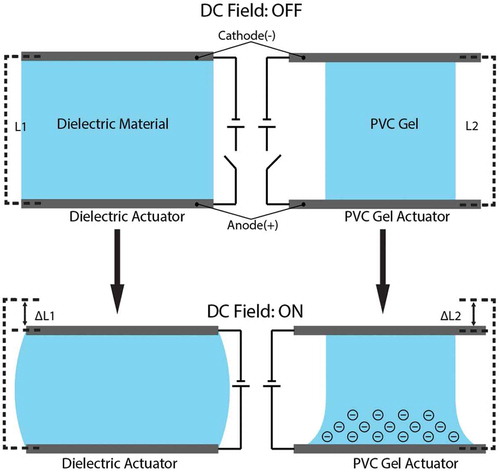
PVC gel stack actuators excel in applications where light weight alternatives to traditional actuators are needed. In [Citation203], discuss the large potential of this material for use as an artificial muscle. PVC artificial muscles (PVCAM) have been usedto make lightweight walking assist devices [Citation204]. In this targeted application the PVCAM assisted walking mechanism was shown to increase the users walking speed by 10% and step length by about 2.8 cm.
Casting methods are typically used to fabricate PVC gel actuators. For instance, in [Citation204] commercialized PVC powder was plasticized by dibutyl adipate (DBA), mixed in a solvent of tetrahydrofuran (THF), then cast in petri dishes and the THF evaporated out at room temperature.
7. Analysis and comparisons
This section provides a performance comparison of materials for use in 3D-printed robots as well as means for fabricating them especially by freeform fabrication techniques such as 3D printing. First, ionic electroactive polymers (EAPs) such as conductive polymers, IPMC, carbon nanotubes (CNT)s and ionic gels are addressed. Then thermal active polymers, such as thermal-responsive SMPs and thermotropic liquid crystal polymers are addressed. Finally, light active polymers such as light-responsive SMPs and phototropic liquid crystal polymers are addressed.
Active polymeric materials can function either in bending or non-bending modes of actuation. Stroke (maximum achievable displacement) is smaller in non-bending actuators than in bending actuators (where bending results from differential strain of bonded layers). Consequently, many of the materials considered are generally fabricated as bending actuators, since a large stroke is desired. The amplitude of oscillation of active materials in response to low frequencies can be estimated from the maximum displacement achieved in response to a step input. However the stroke will be attenuated at higher frequencies. This attenuation is dependent on the response time of the material. Materials with a slower response time will exhibit a more attenuated response to high frequency inputs. It’s common to characterize the displacement of actuators over a range of frequencies, for instance see [Citation83] for IPMCs and CNTs, and see [Citation205] for similar data for conjugated polymer bending actuators.
The relation between the displacement or stroke of a bending actuator and the actuator curvature is approximated as
for thin beams, where is the radius of curvature,
is the tip displacement and
is the original free length of the beam [Citation46]. The relation of the bending curvature and the max compressive and tensile strains is given by
where is the max strain and
is the thickness of the beam [Citation46]. Strain is defined as the displacement normalized by the original material length in the direction of lineal deformation (engineering strain) [Citation46,Citation206]. Typical strain is the strain that is usually manifest in working devices, whereas peak or max strain is the maximum strain reported [Citation206]. Most bending actuators will be manufactured to be less than 200 μm thick.
Also in the proceeding, typical stress is defined as the force per cross-sectional area (whose surface normal is parallel to the direction of lineal deformation) under which actuators are typically tested [Citation206]. Max stress is the max force per cross-sectional area under which the material is able to maintain position (also referred to as blocking stress) [Citation206].
7.1. Ionic electroactive polymers (ionic EAPs)
Most ionic electroactive polymers are fabricated as layered composites that function as bending actuators. These ionic electroactive polymer actuators are attractive for use in mm to cm scale soft mechatronics applications, because they can be directly driven by low voltage electric signals and can function in aqueous environments. They can also function in the air provided they have electrodes and a means of remaining hydrated. They generally exhibit low efficiencies and have lower work densities, which is an obstacle to powering them through an on-board battery. Consequently, they will typically require a wire harnesses. An exception are ionic gels or other ionic EAPs that are operated in electrolytic environments.
and presents some reported values for the operating voltage, charge transfer, efficiency, response time, strain rate, strain, stress, work density and elastic modulus for ionic EAPs such as conductive polymers, IPMCs, carbon nanotube actuators and ionic gels [Citation1,Citation135,Citation206–Citation209]. Though not technically a polymer, carbon nanotube actuators have similar composition and mechanics to ionic EAPs. They are included in the table for completeness.
Table 2. Ionic EAP actuators. Unless otherwise stated, values are from [Citation206]. Material costs are approximate and based on pricing from commercial vendors.
As can be seen, all materials have a typical operating voltage close to 1 volt. Higher continuous operating voltage can potentially be achieved with alternative solvents or use of ionic liquids [Citation126,Citation210]. CNTs have a lower efficiency and strain, but also a lower response time than conductive polymers and IPMCs. All three materials have a maximum strain rate on the order of 10% per sec. Conductive polymers have high work density (on the order of 100 kJ/m3) and strain. Moreover, strain is proportional to the charge density for stresses lower than a few megapascals. Their principle disadvantage is their significant power requirements, indicated by their large charge transfer of up to 100 MC/m3. Carbon nanotube actuators have an especially fast response time and good work density, but are very stiff and exhibit low strain, consequently. IPMCs exhibit a lower work density, but also have lower power requirements than conjugated polymers or CNTs. Since, both IPMCs and CNT actuators are bending actuators, these materials can exhibit a large stroke in spite of low strain. Conjugated polymers can also be utilized in bending actuators, by compositing them with other materials such as noble metal counter electrodes and/or polyelectrolyte ion-exchange layers such as Nafion. Though not represnted in the table, superior ionic EAP bending actuators might be realized in multi-layered structures sandwiching ion-exchange membranes between conjugated polymer layers.
Conjugated polymer bi-layer actuator micro-bots can be fabricated through well-established micromachining methods [Citation3]. Micromachining methods can also be applied to IPMCs [Citation211]. However, these techniques have shape restrictions limited throughput, require specilized equipment and are expensive. There is an established method for fused filament fabrication of IPMCs [Citation8, Citation212]. This method has the advantage of being able to quickly produce a large variety of shapes in a mm to cm size range, which is convenient for fabricating custom soft robots on that scale. The principle drawback is that an extensive activation and plating process follows the 3D printing process which could take several days. However, use of novel electrode materials such as asymmetrically laser-scribed reduced graphene oxide paper (HLrGOP) [Citation92] or conjugated polymers such as polypyrrole [Citation86], which can be composited with the ion-exchange materials through painting and/or hot pressing methods could significantly reduce this extensive manufacturing time. Overall, 3D printing methods are preferable for conveniently fabricating custom 3D geometry.
7.2. Thermally activated polymer actuators
Thermally active polymers are advantageous because they typically have a simpler construction than electroactive polymers. They don’t require electrodes and are generally not composites but rather a single active polymeric material, which is an advantage in manufacturing them. They also exhibit much larger strains than electroactive polymers, which makes them especially useful for applications requiring large shape changes. and presents some reported values for the activation temperature, efficiency, response time, strain rate, strain, stress, work density and elastic modulus for thermotropic liquid crystal polymers and thermal-responsive SMPs [Citation1,Citation23,Citation157,Citation188, Citation206, Citation213–Citation216]. The thermally activated polymers exhibit strains on the order of 800%, but it takes an extensive period to reach this maximum strain. Consequently, the thermally activated polymers technically have a long response time. Notably, however thermotropic LCEs have a larger maximum strain rate than any of the ionic EAPs (37% per sec vs. 19% per sec).
Table 3. Thermal-responsive polymer actuators. Material costs are approximate and based on pricing from commercial vendors.
Figure 42. Ionic electroactive polymer actuators: (a) Conductive polymers, (b) IPMCs, (c) CNTs.
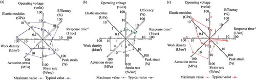
Figure 43. Thermally activated polymer actuators: (a) thermotropic LCEs, (b) thermal-responsive SMPs.
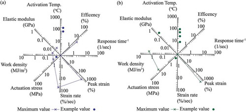
Moreover, though the single value for strain rate for SMPs represented is low (0.125% per sec) it is within the typical operating range of the ionic EAPs (as reported in [Citation206]) and faster speeds may be achievable with different SMP materials, in research that specifically seeks to elicit a fast response. For this reason, the displacement speeds of these thermally active materials may in fact be comparable to or even exceed those of the ionic EAPs. The stress that SMPs are capable of is comparable to that of the ionic EAPs, but liquid crystal elastomers, specifically, have a much lower max stress (0.45 MPa vs. 34 MPa). Due to the large strain that LCEs are capable of however, it has a comparable work density to that of ionic EAPs and the work density of SMPs far exceeds that of the ionic EAPs (2 MJ/m3 vs. 0.1 MJ/m3). The critical shortcoming of the SMP material is irreversible actuation (i.e. the need for a programming step before the SMP can actuate by returning to its undeflected state). However, there is research into SMPs with reversible actuation [Citation146,Citation147]. It is also important to note that thermal-responsive SMPs may exhibit especially dramatic changes in elastic modulus over their operational temperature range (being softer above the transition temperature and harder below it).
The achievement of two-way actuation (continuous fully reversible actuation without need of resets or programming steps) while maintaining the performance values reported here would make SMPs an attractive material for use in robotics applications. Alternatively, liquid crystal polymers that exhibit higher stress and yet maintain relatively high strains and strain rates would also be good candidate materials.
A significant advantage of the thermally active material is their simplicity and wide variety of methods that may be employed to manufacture them consequently, especially for SMPs. The one-way actuation of SMPs can be used to create robots that fold up from planer two-dimensional sheets [Citation158,Citation168,Citation169]. This is achieved by sandwiching a passive structural material (that may have defined hinge regions in addition to other features) between two ‘programmed’ sheets of SMP. Commercially available PEEK sheet readily shrinks up to 50% its original size upon heating above 160°C, as an example [Citation158]. Removal of the SMP material from one side results in an asymmetric strain when the composite is heated, causing the composite to bend as the SMP material shrinks [Citation158]. This approach can leverage 2D techniques like milling and laser cutting to create a large though limited range of complex 3D structures. This approach is similar to other techniques commonly referred to as ‘4D printing’, where flat printed structures reconfigure into the intended 3D design in response to stimulus such as heat. These approaches are very convenient and can in fact achieve fairly intricate designs. However, it should be noted that additional components such as secondary smart polymeric actuator materials for actuation need to be incorporated into the designs, since the function of the SMPs is strictly self-folding to achieve the final design configuration.
Recently, a micro-projection stereolithographic 3D printing method was used to fabricate shape memory polymers using photoinitiator and methacrylates to fabricate liquid crystal copolymer networks [Citation9]. The advantages of this technique are the high resolution achievable (1 µm), quick processing time, and automated material exchange. Additionally, the material properties of the resulting print are tailorable. Specific pieces included prints with a rubber modulus (100 MPa) capable of 300% max strain and activation temperatures over a range from 50°C to 180°C [Citation9]. However, this process only demonstrated the 3D printing of one-way SMPs and the recovery time was on the order of minutes.
One solution to printing reversible actuators utilizing SMP material is to print a composite, using a second actuator such as a hydrogel in the programming step of the SMP [Citation10]. This was achieved using polyjet technology, which can print hydrogels and SMPs using a inkjet to dispense photo-curable resins. Hydrogels can be inconvenient and slow since hydration is the stimulus, but composites of SMPs and other materials could result in other reversible actuators.
7.3. Light activated polymer actuators
presents some reported values for the response time, strain rate, strain, work density and elastic modulus for phototropic liquid crystal polymers and light-responsive SMPs [Citation163,Citation198,Citation218–Citation221]. Light activated polymers are of special interest because they can be remotely adressed and can therefore be used in untethered systems. Phototropic liquid crystal polymers are exceptionally fast with a response time approaching milliseconds [Citation1]. The combination of this with a large stroke when used as bending actuators makes them especially atractive for high-speed applicaitons. Like thermotropic liquid crystal elastomers however, they have a lower work density, and maximum stress output. Consequently they are not suitable for applications that require forceful actuation. There are two kinds of light activated SMPs, as discussed in Section 4, light-triggered thermal-responsive SMPs and light-responsive SMPs [Citation219]. applies to light-triggered thermal-responsive SMPs. only applies to light-responsive SMPs. The key difference between light-triggered thermal-responsive SMPs and light-responsive SMPs is that light-triggered thermal-responsive SMPs generally rely on a phase transitions whereas light-responsive SMPs rely on photo-induced cross-linking and cleaving[Citation163]. There are fewer examples of light-responsive SMPs and satisfactory performance for use in robotics applications has not yet been demonstrated, as can be seen in . Light-triggered thermal-responsive SMPs have a higher work density and maximum stress than phototropic liquid crystal polymers but both Light-triggered thermal-responsive SMPs and light-responsive SMPs also have a much slower response time. Also, light activated SMPs are generally irreversible. Therefore, light activated SMPs are more suitable for applications that require one-off more forceful actuation and are not suited for applications that require rapid continuous actuation.
Table 4. Light-responsive smart polymeric materials.
Phototropic liquid crystal polymers and light-responsive shape memory polymers are more complicated to manufacture than thermal-responsivepolymers because additional steps are required to make the liquid crystal polymers and shape memory polymers responsive to light. This is acomplished by the inclusion of azobenzene dies in liquid crystal polymers and the inclusion of cinnamylidene acetic acid (CAA) or cinnamic acid (CA) groups in shape memory polymers [Citation30,Citation163].
A combination of spin-coating, ink-jet printing and micromachining has been successfully employed to fabricate artificial cilia using a phototropic LCN [Citation6,Citation30]. This approach utilized a polyamide alignment layer and a surfactant to facilitate self-assembly of the mesogens in the printed dispersions and used a radical initiator to maintain mesogen alignment during polymerization [Citation6,Citation30]. The use of spin-coating and micromachining restricts the achievable geometry and throughput and increases the cost of manufacturing. However the approach succeeds as a freeform fabrication method for a fast, high-stroke, remotely-addressible, millimeter-scale to sub actuator.
8. Conclusions and future work
This review has specifically focused on active polymers and gels, fabrication methods and motion control strategies for soft mechatronic devices. A special focus has been given to freeform fabrication methods for on-demand fabrication of custom, monolithic devices. The review of soft active materials in [Citation1] offers a much larger scope, considering more materials but dedicating less treatment to each material individually. These materials may have widely different ideal applications because of the variety in their material properties and performance characteristics. Other review articles are material specific. There is limited prior literature that attempts to assemble information regarding the mechanics, manufacturing and motion control of a variety of active polymers and gels because of their potential for use in mm-scale to cm-scale soft mechatronics and robotics applications and because of their potential for fabrication through freeform fabrication methods. This review strives to give the reader a functional basis for working with multiple active polymers and gels and freeform fabrication methods and conducts side-by-side performance comparisons.
Polymeric and gel based soft mechatronic and robotic devices require fabrication methods that can produce a large variety of shapes, are fast, inexpensive and have high resolution and reliability. These devices also require active materials that have adequate performance in terms of stroke, strain rate, achievable material stress and energy requirements and have developed motion control strategies. There is still significant research to be done to understand and improve the performance of active polymers and gels and to improve fabrication methods and motion control strategies. This review especially compares the performance characteristics of active polymers and gels. A complementary endeavor would be to analyze the performance requirements of potential applications of such active polymers and gels (as is done in [Citation207]) at different scales.
There are also significant opportunities to improve the freeform fabrication of active polymers and gels. For instance, research in additive manufacturing of IPMCs and related ionic EAPs could consider alternative ionomeric and electrode materials and different additive manufacturing methods to decrease the cost, increase resolution and increase throughput. Research might investigate new in situ functionalization techniques to rapidly convert materials commonly printed through additive manufacturing (such as polystyrene) to polyelectrolytes capable of functioning as ion-exchange membranes. Additionally, use of precursor to ionomeric material (the approach in [Citation8]) might be extended to other additive manufacturing technologies capable of fine resolution, such as selective laser sintering and stereolithographic 3D printing. The time required to print the structure in a precursor material and then subsequently functionalize it is reduced for thinner structures, proportionally to the thickness. These efforts could also leverage alternative electrode materials such as conducting polymers that enable rapid deposition of electrodes on ionomeric structures. This would provide a process by which a variety of conventional additive manufacturing techniques and materials could be utilized to print precursor structures that could be rapidly functionalized and composited with electrodes, to create active monolithic soft structures.
Alternatively, another avenue of research would be to further develop freeform fabrication methods for IPMCs that employ printable dispersions of ionomeric materials, such as the method exhibited in [Citation4] to demonstrate the fabrication of custom shapes and reduce the drying time. This would also allow for the printing of the electrode material. It would also be worthwhile to further develop freeform fabrication methods for conjugated polymers and liquid crystal polymers, since conjugated polymers have the highest work density of the reversible active polymers considered and liquid crystal polymers exhibit the highest strain and strain rate of the active polymers considered, do not require electrodes and can be remotely actuated.
Ultimately, research into freeform fabrication of active polymers and gels should aim at low cost, high resolution and high throughput fabrication methods. This will enable rapid prototyping and on-site fabrication of soft active monolithic mechatronic and robotic devices.
In addition to freeform fabrication of active polymers and gels, effective motion control is another ongoing challenge. In general, all active polymers and gels are subject to changing dynamics and environmental sensitivity and are difficult to integrate with accurate and reliable sensors. This makes precision motion control challenging without resorting to extrinsic sensors, such as cameras and laser displacement sensors. Therefore, there is value in investigating and reducing the sensitivity of active polymers and gels to environmental conditions and in improving the sensing capabilities of active polymers and gels. In some applications of soft active polymers and gels, precision control might be unnecessary. None-the-less, it may still be desirable to make the best use of available sensor data and to choose effective control policies in spite of uncertainty. There is, therefore, value in motion control strategies that address significant uncertainty in sensor data and model dynamics.
Acknowledgments
Authors acknowledge financial support from the National Science Foundation (NSF), Partnerships for International Research and Education (PIRE) Program, Grant No. 1545857. Any opinions, findings, and conclusions or recommendations expressed in this material are those of the author(s) and do not necessarily reflect the views of the NSF. Authors also gratefully acknowledge Prof. Kwang J. Kim and Dr. Kinji Asaka for inspiring this article through the 2017 International Workshop on Active Materials and Soft Mechatronics (AMSM), National Institute of Advanced Industrial Science and Technology (AIST), Japan.
Disclosure statement
No potential conflict of interest was reported by the authors.
Additional information
Funding
References
- L. Hines, K. Petersen, G.Z. Lum, and M. Sitti, Soft actuators for small-scale robotics, Advan. Mater. 29 (2017), pp. 1603483.
- E.W. Jager, O. Ingan¨As, and I. Lundstr¨Om, Microrobots for micrometer-size objects in aqueous media: Potential tools for single-cell manipulation, Science 288 (5475) (2000), pp. 2335–2338.
- E.W. Jager, E. Smela, and O. Ingan¨As, Microfabricating conjugated polymer actuators, Science 290 (5496) (2000), pp. 1540–1545.
- E. Malone and H. Lipson, Freeform fabrication of ionomeric polymer-metal composite actuators, Rapid Prot. J. 12 (5) (2006), pp. 244–253.
- G.H. Kwon, J.Y. Park, J.Y. Kim, M.L. Frisk, D.J. Beebe, and S.-H. Lee, Biomimetic soft multifunctional miniature aquabots, Small 4 (12) (2008), pp. 2148–2153.
- C.L. Van Oosten, C.W. Bastiaansen, and D.J. Broer, Printed artificial cilia from liquid-crystal network actuators modularly driven by light, Nat. Mater. 8 (8) (2009), pp. 677.
- D. Morales, E. Palleau, M.D. Dickey, and O.D. Velev, Electro-actuated hydrogel walkers with dual responsive legs, Soft Matt. 10 (9) (2014), pp. 1337–1348.
- J.D. Carrico, N.W. Traeden, M. Aureli, and K.K. Leang, Fused filament 3D printing of ionic polymer-metal composites (IPMCs), Smart Mater. Struct 24 (12) (2015), pp. 125021.
- Q. Ge, A.H. Sakhaei, H. Lee, C.K. Dunn, N.X. Fang, and M.L. Dunn, Multimaterial 4D printing with tailorable shape memory polymers, Sci. Rep. 6 (2016), pp. 31110.
- Y. Mao, Z. Ding, C. Yuan, S. Ai, M. Isakov, J. Wu, T. Wang, M.L. Dunn, and H.J. Qi, 3D printed reversible shape changing components with stimuli responsive materials, Sci. Rep. 6 (2016), pp. 24761.
- J.D. Carrico, K.J. Kim, and K.K. Leang, 3D-printed ionic polymer-metal composite soft crawling robot, IEEE International Conference on Robotics and Automation (ICRA), Singapore, 2017.
- D. Rus and M.T. Tolley, Design, fabrication and control of soft robots, Nature 521 (7553) (2015), pp. 467.
- M.T. Tolley, R.F. Shepherd, B. Mosadegh, K.C. Galloway, M. Wehner, M. Karpelson, R.J. Wood, and G.M. Whitesides, A resilient, untethered soft robot, Soft Robotics 1 (3) (2014), pp. 213–223.
- A.A.A. Moghadam, A. Kouzani, K. Torabi, A. Kaynak, and M. Shahinpoor, Development of a novel soft parallel robot equipped with polymeric artificial muscles, Smart Mater. Struct. 24 (3) (2015), pp. 035017.
- H. Wang, J. Chen, H.Y. Lau, and H. Ren, Motion planning based on learning from demonstration for multiple-segment flexible soft robots actuated by electroactive polymers, IEEE Robotics Automat. Lett. 1 (1) (2016), pp. 391–398.
- R.K. Jain, S. Majumder, and A. Dutta, Scara based peg-in-hole assembly using compliant IPMC micro gripper, Rob. Auton. Syst. 61 (3) (2013), pp. 297–311.
- Z. Ye, P. Hou, and Z. Chen, 2D maneuverable robotic fish propelled by multiple ionic polymer–Metal composite artificial fins, Int. J. Intell. Robotics Appl. 1 (2) (2017), pp. 1–14.
- K.T. Nguyen, S.Y. Ko, J.-O. Park, and S. Park, Miniaturized terrestrial walking robot using PVDF/PVP/PSSA based ionic polymer–Metal composite actuator, J. Mech. Robot 8 (4) (2016), pp. 041006.
- M. Aureli, V. Kopman, and M. Porfiri, Free-locomotion of underwater vehicles actuated by ionic polymer metal composites, IEEE/ASME Trans. Mechatron. 15 (4) (2010), pp. 603–614.
- C.T. Nguyen, H. Phung, T.D. Nguyen, C. Lee, U. Kim, D. Lee, H. Moon, J. Koo, J.-D. Nam, and H.R. Choi, A small biomimetic quadruped robot driven by multistacked dielectric elastomer actuators, Smart Mater. Struct. 23 (6) (2014), pp. 065005.
- C.T. Nguyen, H. Phung, H. Jung, U. Kim, T.D. Nguyen, J. Park, H. Moon, J.C. Koo, and H.R. Choi, Printable monolithic hexapod robot driven by soft actuator, IEEE International Conference on Robotics and Automation (ICRA), Seattle, 2015
- S. Miyashita, S. Guitron, K. Yoshida, S. Li, D.D. Damian, and D. Rus, Ingestible, controllable, and degradable origami robot for patching stomach wounds, IEEE International Conference on Robotics and Automation (ICRA), Stockholm, 2016
- H. Wermter and H. Finkelmann, Liquid crystalline elastomers as artificial muscles, E- Polymers 1 (1) (2001), pp. 111–123.
- A.H. Gelebart, D.J. Mulder, M. Varga, A. Konya, G. Vantomme, E. Meijer, R.L. Selinger, and D.J. Broer, Making waves in a photoactive polymer film, Nature 546 (7660) (2017), pp. 632.
- R. Tiwari and E. Garcia, The state of understanding of ionic polymer metal composite architecture: A review, Smart Mater. Struct. 20 (8) (2011), pp. 083001.
- C. Jo, D. Pugal, I. Oh, K.J. Kim, and K. Asaka, Recent advances in ionic polymer-metal composite actuators and their modeling and applications, Prog. Polym. Sci. 38 (7) (2013), pp. 1037–1066.
- Y. Bahramzadeh and M. Shahinpoor, A review of ionic polymeric soft actuators and sensors, Soft Robotics 1 (1) (2014), pp. 38–52.
- J. Le Bideau, L. Viau, and A. Vioux, Ionogels, ionic liquid based hybrid materials, Chem. Soc. Rev. 40 (2) (2011), pp. 907–925.
- T.J. White and D.J. Broer, Programmable and adaptive mechanics with liquid crystal polymer networks and elastomers, Nat. Mater. 14 (11) (2015), pp. 1087.
- C. Ohm, M. Brehmer, and R. Zentel, Liquid crystalline elastomers as actuators and sensors, Advan. Mater. 22 (31) (2010), pp. 3366–3387.
- Q. Zhao, H.J. Qi, and T. Xie, Recent progress in shape memory polymer: New behavior, enabling materials, and mechanistic understanding, Prog. Polym. Sci. 49 (2015), pp. 79–120.
- Y. Liu, H. Du, L. Liu, and J. Leng, Shape memory polymers and their composites in aerospace applications: A review, Smart Mater. Struct. 23 (2) (2014), pp. 023001.
- J.D. Carrico, J.M. Erickson, and K.K. Leang, Characterization of 3D-printed IPMC actuators, SPIE Smart Structures and Materials and Nondestructive Evaluation and Health Monitoring, Las Vegas, 2016.
- P. De Gennes, K. Okumura, M. Shahinpoor, and K. Kim, Mechanoelectric effects in ionic gels, Europhys. Lett. 50 (4) (2000), pp. 513.
- Y. Cha and M. Porfiri, Mechanics and electrochemistry of ionic polymer metal composites, J. Mech. Phys. Solids. 71 (2014), pp. 156–178.
- I.-S. Park, S.-M. Kim, D. Pugal, L. Huang, S.-W. Tam-Chang, and K.J. Kim, Visualization of the cation migration in ionic polymer–Metal composite under an electric field, Appl.Phys.Lett. 96 (4) (2010), pp. 043301.
- M. Shahinpoor and K.J. Kim, Ionic polymer–Metal composites: III. Modeling and simulation as biomimetic sensors, actuators, transducers, and artificial muscles, Smart Mater. Struct. 13 (2004), pp. 1362–1388.
- S. Nemat-Nasser and J.Y. Li, Electromechanical response of ionic polymer-metal composites, J. Appl. Phys. 87 (7) (2000), pp. 3321–3331.
- M. Porfiri, An electromechanical model for sensing and actuation of ionic polymer metal composites, Smart Mater. Struct. 18 (1) (2008), pp. 015016.
- E. Biddiss and T. Chau, Electroactive polymeric sensors in hand prostheses: Bending response of an ionic polymer metal composite, Med. Eng. Phys. 28 (6) (2006), pp. 568–578.
- M. Aureli and M. Porfiri, Nonlinear sensing of ionic polymer metal composites, Continuum Mech. Thermodynamics 25 (2–4) (2013), pp. 273–310.
- S. Kang, J. Shin, S.J. Kim, H.J. Kim, and Y.H. Kim, Robust control of ionic polymer–Metal composites, Smart Mater. Struct. 16 (6) (2007), pp. 2457.
- M.J. Fleming, K.J. Kim, and K.K. Leang, Mitigating IPMC back relaxation through feedforward and feedback control of patterned electrodes, Smart Mater. Struct. 21 (8) (2012), pp. 085002.
- Y. Bar-Cohen, S. Leary, K. Oguro, S. Tadokoro, J. Harrison, J. Smith, and J. Su, Challenges to the application of IPMC as actuators of planetary mechanisms, SPIE International Symposium on Smart Structures and Materials, Newport, 2000.
- X.-L. Wang, I.-K. Oh, J. Lu, J. Ju, and S. Lee, Biomimetic electro-active polymer based on sulfonated poly (styrene-b-ethylene-co-butylene-b-styrene), Mater. Lett. 61 (29) (2007), pp. 5117–5120.
- M. Shahinpoor and K.J. Kim, Ionic polymer-metal composites: I. Fundamentals, Smart Mater. Struct.. 10 (2001), pp. 819–833.
- T. Wallmersperger, B. Kröplin, and R.W. Gülch, Coupled chemo-electro-mechanical formulation for ionic polymer gels––Numerical and experimental investigations, Mechanics Mater. 36 (5–6) (2004), pp. 411–420.
- T. Wallmersperger, D.J. Leo, and C.S. Kothera, Transport modeling in ionomeric polymer transducers and its relationship to electromechanical coupling, J. Appl. Phys. 101 (2) (2007), pp. 024912.
- T. Wallmersperger, B.J. Akle, D.J. Leo, and B. Kröplin, Electrochemical response in ionic polymer transducers: An experimental and theoretical study, Compos. Sci. Technol. 68 (5) (2008), pp. 1173–1180.
- M. Aureli, C. Prince, M. Porfiri, and S.D. Peterson, Energy harvesting from base excitation of ionic polymer metal composites in fluid environments, Smart Mater. Struct. 19 (1) (2009), pp. 015003.
- M. Aureli, W. Lin, and M. Porfiri, On the capacitance-boost of ionic polymer metal composites due to electroless plating: Theory and experiments, J. Appl. Phys. 105 (10) (2009), pp. 104911.
- Y. Bar-Cohen (ed.), Electroactive Polymer (EAP) Actuators as Artificial Muscles: Reality, Potential, and Challenges, SPIE Press, Bellingham, 2004.
- M. Shahinpoor, Y. Bar-Cohen, J.O. Simpson, and J. Smith, Ionic polymer-metal composites (IPMCs) as biomimetic sensors, actuators and artificial muscles-a review, Smart Mater. Struct. 7 (6) (1998), pp. R15–R30.
- Y. Cha, M. Aureli, and M. Porfiri, A physics-based model of the electrical impedance of ionic polymer metal composites, J. Appl. Phys. 111 (12) (2012), pp. 124901.
- Y. Cha, H. Kim, and M. Porfiri, Energy harvesting from the tail beating of a carangiform swimmer using ionic polymer–Metal composites, Bioinspir. Biomim. 8 (3) (2013), pp. 036003.
- Y. Cha, F. Cellini, and M. Porfiri, Electrical impedance controls mechanical sensing in ionic polymer metal composites, Phys. Rev. E 88 (6) (2013), pp. 062603.
- A. Lucantonio, P. Nardinocchi, and L. Teresi, Transient analysis of swelling-induced large deformations in polymer gels, J. Mech. Phys. Solids 61 (1) (2013), pp. 205–218.
- P. Nardinocchi and M. Pezzulla, Curled actuated shapes of ionic polymer metal composites strips, J. Appl. Phys. 113 (22) (2013), pp. 224906.
- B.J. Akle, D.J. Leo, M.A. Hickner, and J.E. McGrath, Correlation of capacitance and actuation in ionomeric polymer transducers, J. Mater. Sci. 40 (14) (2005), pp. 3715–3724.
- X. Tan, D. Kim, N. Usher, D. Laboy, J. Jackson, A. Kapetanovic, J. Rapai, B. Sabadus, and X. Zhou, An autonomous robotic fish for mobile sensing, in IEEE/RSJ International Conference on Intelligent Robots and Systems, Beijing, 2006.
- K.J. Kim, D. Pugal, and K.K. Leang, A twistable ionic polymer-metal composite artificial muscle for marine applications, Marine Technol. Soc. J. 45 (4) (2011), pp. 83–98.
- V. Palmre, J.J. Hubbard, M. Fleming, D. Pugal, S. Kim, K.J. Kim, and K.K. Leang, An IPMC-enabled bio-inspired bending/twisting fin for underwater applications, Smart Mater. Struct. 22 (1) (2013), pp. 014003.
- J.J. Hubbard, M. Fleming, V. Palmre, D. Pugal, K.J. Kim, and K.K. Leang, Monolithic IPMC fins for propulsion and maneuvering in bioinspired underwater robotics, IEEE J. Oceanic Eng. 39 (3) (2014), pp. 540–551.
- P. Arena, C. Bonomo, L. Fortuna, M. Frasca, and S. Graziani, Design and control of an IPMC wormlike robot, IEEE Trans. Syst. Man, Cybernet. B. Cybernet. 36 (5) (2006), pp. 1044–1052.
- T.T. Nguyen, N.S. Goo, V.K. Nguyen, Y. Yoo, and S. Park, Design, fabrication, and experimental characterization of a flap valve IPMC micropump with a flexibly supported diaphragm, Sens. Actuators A Phys. 141 (2) (2008), pp. 640–648.
- B.-K. Fang, M.-S. Ju, and -C.-C.K. Lin, A new approach to develop ionic polymer–Metal composites (IPMC) actuator: Fabrication and control for active catheter systems, Sens. Actuators A Phys. 137 (2) (2007), pp. 321–329.
- W.J. Yoon, P.G. Reinhall, and E.J. Seibel, Analysis of electro-active polymer bending: A component in a low cost ultrathin scanning endoscope, Sens. Actuators A Phys. 133 (2) (2007), pp. 506–517.
- The Chemours Company FC, LLC, Nafion N115, N117, N110 Ion Exchange Materials: Extrusion Cast Membranes, Fayetteville, NC, 2016. Available at: https://www.chemours.com/Nafion/en_US/index.html.
- K. Asaka, N. Fujiwara, K. Oguro, k. Onishi, and S. Sewa, State of water and ionic conductivity of solid polymer electrolyte membranes in relation to polymer actuators, J. Electroanal. Chem. 505 (1–2) (2001), pp. 24–32.
- S. Nemat-Nasser and S. Zamani, Experimental study of nafion- and flemion-based ionic polymer metal composites (IPMCs) with ethylene glycol as solvent, Smart Struct. Mater. 5051 (2003), pp. 233–244.
- Solvay Specialty Polymers, Aquivion E87-05s, Fayetteville, NC, 2017. Available at: http://www.solvay.com/.
- N. Yoshida, T. Ishisaki, A. Watakabe, and M. Yoshitake, Characterization of flemion membranes for PEFC, Electrochim. Acta 43 (24) (1998), pp. 3749–3754.
- M. Luqman, J.-W. Lee, -K.-K. Moon, and Y.-T. Yoo, Sulfonated polystyrene-based ionic polymer–Metal composite (IPMC) actuator, J. Ind. Eng. Chem. 17 (1) (2011), pp. 49–55.
- X.-L. Wang, I.-K. Oh, and T.-H. Cheng, Electro-active polymer actuators employing sulfonated poly (styrene-ran-ethylene) as ionic membranes, Polym. Int. 59 (3) (2010), pp. 305–312.
- Y. Tang, Z. Xue, X. Zhou, X. Xie, and C.-Y. Tang, Novel sulfonated polysulfone ion exchange membranes for ionic polymer–Metal composite actuators, Sens. Actuators B Chem. 202 (2014), pp. 1164–1174.
- V. Panwar, S.Y. Ko, J.-O. Park, and S. Park, Enhanced and fast actuation of fullerenol/PVDF/PVP/PSSA based ionic polymer metal composite actuators, Sens. Actuators B Chem. 183 (2013), pp. 504–517.
- K.A. Mauritz and R.B. Moore, State of understanding of Nafion, Chem. Rev. 104 (10) (2004), pp. 4535–4586.
- S.J. Lee, M.J. Han, S.J. Kim, J.Y. Jho, H.Y. Lee, and Y.H. Kim, A new fabrication method for IPMC actuators and application to artificial fingers, Smart Mater, Struct. 15 (2006), pp. 1217–1224.
- K.J. Kim and M. Shahinpoor, A novel method of manufacturing three-dimensional ionic polymer-metal composites (IPMCs) biomimetic sensors, actuators and artificial muscles, Polymer 43 (3) (2002), pp. 797–802.
- S. Trabia, Z. Olsen, T. Hwang, and K.J. Kim, Producing intricate IPMC shapes by means of spray-painting and printing (conference presentation), in SPIE Smart Structures and Materials & Nondestructive Evaluation and Health Monitoring, San Francisco, 2017.
- DuPont Fluoroproducts, Chemical Treatment of Nafion PFSA Resins R-1100 and R-1000, DuPont Fluoroproducts, Fayetteville, NC, Nov 2002. Available at: www.ion-power.com.
- K.J. Kim and M. Shahinpoor, Ionic polymer-metal composites: II. manufacturing techniques, Smart Mater. Struct. 12 (1) (2003), pp. 65–79.
- V. Palmre, D. Pugal, K.J. Kim, K.K. Leang, K. Asaka, and A. Aabloo, Nanothorn electrodes for ionic polymer-metal composite artificial muscles, Sci. Rep. 4 (6176) (2014), pp. 1–10.
- S.-M. Kim and K.J. Kim, Palladium buffer-layered high performance ionic polymer–Metal composites, Smart Mater. Struct. 17 (3) (2008), pp. 035011.
- C.-K. Chung, P. Fung, Y. Hong, M.-S. Ju, -C.-C.K. Lin, and T. Wu, A novel fabrication of ionic polymer-metal composites (IPMC) actuator with silver nano-powders, Sens. Actuators B Chem. 117 (2) (2006), pp. 367–375.
- J. Kim, S.-H. Bae, M. Kotal, T. Stalbaum, K.J. Kim, and I.-K. Oh, Soft but powerful artificial muscles based on 3D graphene–CNT-Ni heteronanostructures, Small 13 (31) (2017), pp. 1701314.
- J.-H. Jeon and I.-K. Oh, Selective growth of platinum electrodes for MDOF IPMC actuators, Thin Solid Films 517 (17) (2009), pp. 5288–5292.
- B. Akle, S. Nawshin, and D. Leo, Reliability of high strain ionomeric polymer transducers fabricated using the direct assembly process, Smart Mater. Struct. 16 (2) (2007), pp. S256.
- B.J. Akle, M.D. Bennett, D.J. Leo, K.B. Wiles, and J.E. McGrath, Direct assembly process: A novel fabrication technique for large strain ionic polymer transducers, J. Mater. Sci. 42 (16) (2007), pp. 7031–7041.
- F. Cellini, A. Grillo, and M. Porfiri, Ionic polymer metal composites with polypyrrole-silver electrodes, Appl.Phys.Lett. 106 (13) (2015), pp. 131902.
- A. Aabloo, V. De Luca, G. Di Pasquale, S. Graziani, C. Gugliuzzo, U. Johanson, C. Marino, A. Pollicino, and R. Puglisid, A new class of ionic electroactive polymers based on green synthesis, Sens. Actuators A Phys. 249 (2016), pp. 32–44.
- J. Kim, J.-H. Jeon, H.-J. Kim, H. Lim, and I.-K. Oh, Durable and water-floatable ionic polymer actuator with hydrophobic and asymmetrically laser-scribed reduced graphene oxide paper electrodes, ACS Nano 8 (3) (2014), pp. 2986–2997.
- J.D. Carrico, N.W. Traeden, M. Aureli, and K.K. Leang, Fused filament additive manufacturing of ionic polymer-metal composite soft active 3D structures, ASME Conference on Smart Materials, Adaptive Structures and Intelligent Systems (SMASIS), Colorado Springs, 2015.
- S. Trabia, Z. Olsen, and K.J. Kim, Searching for a new ionomer for 3D printable ionic polymer-metal composites: Aquivion as a candidate, Smart Mater. Struct. 26 (2017), pp. 115029.
- M. Yamakita, N. Kamamichi, T. Kozuki, K. Asaka, and Z.-W. Luo, Control of biped walking robot with IPMC linear actuator, IEEE/ASME International Conference on Advanced Intelligent Mechatronics, Monterey, 2005.
- K. Takagi, Z.W. Luo, K. Asaka, and K. Tahara, Limited-angle motor using ionic polymer-metal composite, SPIE Smart Structures and Materials and Nondestructive Evaluation and Health Monitoring, San Diego, 2005.
- S. Song, Y. Shan, K.J. Kim, and K.K. Leang, Tracking control of oscillatory motion in IPMC actuators for underwater applications, IEEE/ASME International Conference on Advanced Intelligent Mechatronics (AIM), Montréal, 2010.
- S. Nemat-Nasser, S. Zamani, and Y. Tor, Effect of solvents on the chemical and physical properties of ionic polymer-metal composites, J. Appl. Phys. 99 (10) (2006), pp. 104902.
- V. Vunder, A. Punning, and A. Aabloo, Mechanical interpretation of back-relaxation of ionic electroactive polymer actuators, Smart Mater. Struct. 21 (11) (2012), pp. 115023.
- M. Porfiri, A. Leronni, and L. Bardella, An alternative explanation of back-relaxation in ionic polymer metal composites, Extreme Mechan. Lett. 13 (2017), pp. 78–83.
- Z. Chen, K.-Y. Kwon, and X. Tan, Integrated IPMC/PVDF sensory actuator and its validation in feedback control, Sens. Actuators A Phys. 144 (2) (2008), pp. 231–241.
- K. Kruusamae, P. Brunetto, S. Graziani, A. Punning, G. Di Pasquale, and A. Aabloo, Self-sensing ionic polymer-metal composite actuating device with patterned surface electrodes, Polym. Int. 59 (3) (2009), pp. 300–304.
- A. Punning, K.J. Kim, V. Palmre, F. Vidal, C. Plesse, N. Festin, A. Maziz, K. Asaka, T. Sugino, G. Alici, G. Spinks, G. Wallace, I. Must, I. Põldsalu, V. Vunder, R. Temmer, K. Kruusamäe, J. Torop, F. Kaasik, P. Rinne, U. Johanson, A.-L. Peikolainen, T. Tamm, and A. Aabloo, Ionic electroactive polymer artificial muscles in space applications, Sci. Rep. 4 (2014), pp. 6913.
- M.A. Tsugawa, V. Palmre, J.D. Carrico, K.J. Kim, and K.K. Leang, Slender tube-shaped and square rod-shaped IPMC actuators with integrated sensing for soft mechatronics, Meccanica 50 (11) (2015), pp. 2781–2795.
- V. Vunder, M. Itik, I. Poldsalu, A. Punning, and A. Aabloo, Inversion-based control of ionic polymer–Metal composite actuators with nanoporous carbon-based electrodes, Smart Mater. Struct. 23 (2) (2013), pp. 025010.
- Z. Chen and X. Tan, A control-oriented and physics-based model for ionic polymer–Metal composite actuators, IEEE/ASME Trans. Mechatron. 13 (5) (2008), pp. 519–529.
- P.C. Branco and J. Dente, Derivation of a continuum model and its electric equivalent-circuit representation for ionic polymer–Metal composite (IPMC) electromechanics, Smart Mater. Struct. 15 (2) (2006), pp. 378.
- M. Porfiri, Charge dynamics in ionic polymer metal composites, J. Appl. Phys. 104 (10) (2008), pp. 104915.
- Y. Cha, M. Aureli, and M. Porfiri, A physics-based model of the electrical impedance of ionic polymer metal composites, J. Appl. Phys. 111 (12) (2012), pp. 124901.
- X. Bao, Y. Bar-Cohen, and S. Li, Measurements and macro models of ionomeric polymer-metal composites (IMPC), SPIE International Symposium on Smart Structures, EAPAD Conference, San Diego, 2002.
- J.W. Paquette, K.J. Kim, J.-D. Nam, and Y.S. Tak, An equivalent circuit model for ionic polymer-metal composites and their performance improvement by a clay-based polymer nano-composite technique, ASME International Mechanical Engineering Congress and Exposition, New Orleans, 2002.
- C. Bonomo, L. Fortuna, P. Giannone, and S. Graziani, A circuit to model the electrical behavior of an ionic polymer-metal composite, IEEE Trans. Circuits Syst. 53 (2) (2006), pp. 338–350.
- R.C. Richardson, M.C. Levesley, M.D. Brown, J.A. Hawkes, K. Watterson, and P.G. Walker, Control of ionic polymer metal composites, IEEE/ASME Trans. Mechatron. 8 (2) (2003), pp. 245–253.
- Y. Shan and K.K. Leang, Frequency-weighted feedforward control for dynamic compensation in ionic polymer-metal composite actuators, Smart Mater. Struct. 18 (12) (2009), pp. 125016.
- B.C. Lavu, M.P. Schoen, and A. Mahajan, Adaptive intelligent control of ionic polymer–Metal composites, Smart Mater. Struct. 14 (4) (2005), pp. 466.
- J. Brufau-Penella, K. Tsiakmakis, T. Laopoulos, and M. Puig-Vidal, Model reference adaptive control for an ionic polymer metal composite in underwater applications, Smart Mater. Struct. 17 (4) (2008), pp. 045020.
- A. McDaid, K. Aw, S. Xie, and E. Haemmerle, Gain scheduled control of IPMC actuators with model-free iterative feedback tuning, Sens. Actuators A Phys. 164 (1) (2010), pp. 137–147.
- A. McDaid, K. Aw, E. Haemmerle, M. Shahinpoor, and S. Xie, Adaptive tuning of a 2dof controller for robust cell manipulation using IPMC actuators, J. Micromech. Microeng. 21 (12) (2011), pp. 125004.
- K.K. Ahn, D.Q. Truong, D.N.C. Nam, J.I. Yoon, and S. Yokota, Position control of ionic polymer metal composite actuator using quantitative feedback theory, Sens. Actuators A Phys. 159 (2) (2010), pp. 204–212.
- E. Smela, Conjugated polymer actuators for biomedical applications, Advan. Mater. 15 (6) (2003), pp. 481–494.
- G. Alici, B. Mui, and C. Cook, Bending modeling and its experimental verification for conducting polymer actuators dedicated to manipulation applications, Sens. Actuators A Phys. 2 (126) (2006), pp. 396–404.
- L. Bay, K. West, P. Sommer-Larsen, S. Skaarup, and M. Benslimane, A conducting polymer artificial muscle with 12% linear strain, Advan. Mater. 15 (4) (2003), pp. 310–313.
- Y. Fang, Conjugated polymer actuators and sensors: Modeling, control, and applications, Ph.D. diss., Michigan State University, 2009.
- H.J. Kwon, Y. Osada, and J.P. Gong, Polyelectrolyte gels-fundamentals and applications, Polymer J. 38 (12) (2006), pp. 1211–1219.
- E. Palleau, D. Morales, M.D. Dickey, and O.D. Velev, Reversible patterning and actuation of hydrogels by electrically assisted ionoprinting, Nat. Commun. 4 (2257) (2013), pp. 2257.
- M. Armand, F. Endres, D.R. MacFarlane, H. Ohno, and B. Scrosati, Ionic-liquid materials for the electrochemical challenges of the future, Nat. Mater 8 (8) (2009), pp. 621–629.
- R. Baughman, Conducting polymer artificial muscles, Synth. Met. 78 (3) (1996), pp. 339–353.
- R. Temmer, A. Maziz, C. Plesse, A. Aabloo, F. Vidal, and T. Tamm, In search of better electroactive polymer actuator materials: Ppy versus pedot versus pedot–Ppy composites, Smart Mater. Struct. 22 (10) (2013), pp. 104006.
- E. Smela, Microfabrication of ppy microactuators and other conjugated polymer devices, J. Micromech. Microeng. 9 (1) (1999), pp. 1.
- S. Bhadra, D. Khastgir, N.K. Singha, and J.H. Lee, Progress in preparation, processing and applications of polyaniline, Prog. Polym. Sci. 34 (8) (2009), pp. 783–810.
- M.A.B.H. Susan, T. Kaneko, A. Noda, and M. Watanabe, Ion gels prepared by in situ radical polymerization of vinyl monomers in an ionic liquid and their characterization as polymer electrolytes, J. Am. Chem. Soc. 127 (13) (2005), pp. 4976–4983.
- Z. Wang, B. He, X. Liu, and Q. Wang, Development and modeling of a new ionogel based actuator, J. Intell Mater. Syst. Struct 28 (15) (2017), pp. 2036–2050.
- P. Izak, S.ˇ. Hovorka, T. Bartovsky`, L. Bartovska, and J. Crespo, Swelling of polymeric membranes in room temperature ionic liquids, J. Memb. Sci. 296 (1) (2007), pp. 131–138.
- D. Zhou, G.M. Spinks, G.G. Wallace, C. Tiyapiboonchaiya, D.R. MacFarlane, M. Forsyth, and J. Sun, Solid state actuators based on polypyrrole and polymer-in-ionic liquid electrolytes, Electrochim. Acta 48 (14) (2003), pp. 2355–2359.
- T. Fukushima, K. Asaka, A. Kosaka, and T. Aida, Fully plastic actuator through layer-by-layer casting with ionic-liquid-based bucky gel, Angewandte Chemie Int. Ed. 44 (16) (2005), pp. 2410–2413.
- K. Mukai, K. Asaka, K. Kiyohara, T. Sugino, I. Takeuchi, T. Fukushima, and T. Aida, High performance fully plastic actuator based on ionic-liquid-based bucky gel, Electrochim. Acta 53 (17) (2008), pp. 5555–5562.
- N. Kamamichi, T. Maeba, M. Yamakita, and T. Mukai, Fabrication of bucky gel actuator/sensor devices based on printing method, IEEE/RSJ International Conference on Intelligent Robots and Systems, Nice, 2008.
- S.W. John, G. Alici, and C.D. Cook, Inversion-based feedforward control of polypyrrole trilayer bender actuators, IEEE/ASME Trans. Mechatron. 15 (1) (2010), pp. 149–156.
- Y. Wu, G. Alici, J.D. Madden, G.M. Spinks, and G.G. Wallace, Soft mechanical sensors through reverse actuation in polypyrrole, Adv. Funct. Mater. 17 (16) (2007), pp. 3216–3222.
- S.W. John, G. Alici, and C.D. Cook, Towards the position control of conducting polymer trilayer bending actuators with integrated feedback sensor, IEEE/ASME International Conference on Advanced Intelligent Mechatronics, Singapore, 2009.
- K. Kruusama¨E, A. Punning, A. Aabloo, and K. Asaka, Self-sensing ionic polymer actuators: A review, Actuators 4 (1) (2015), pp. 17–38.
- Y. Fang, X. Tan, and G. Alici, Robust adaptive control of conjugated polymer actuators, IEEE Trans. Control Syst. Technol. 16 (4) (2008), pp. 600–612.
- C.M. Druitt and G. Alici, Intelligent control of electroactive polymer actuators based on fuzzy and neurofuzzy methodologies, IEEE/ASME Trans. Mechatron. 19 (6) (2014), pp. 1951–1962.
- T. Chung, A. Romo-Uribe, and P.T. Mather, Two-way reversible shape memory in a semicrystalline network, Macromolecules 41 (1) (2008), pp. 184–192.
- M. Bothe and T. Pretsch, Bidirectional actuation of a thermoplastic polyurethane elastomer, J. Mater. Chem. 1 (46) (2013), pp. 14491–14497.
- M. Behl, K. Kratz, J. Zotzmann, U. N¨Ochel, and A. Lendlein, Reversible bidirectional shape- memory polymers, Advan. Mater. 25 (32) (2013), pp. 4466–4469.
- Y. Mao, Z. Ding, C. Yuan, S. Ai, M. Isakov, J. Wu, T. Wang, M.L. Dunn, and H.J. Qi, 3d printed reversible shape changing components with stimuli responsive materials, Sci. Rep. 24761 (6) (2016), pp. 1–13.
- A. Lendlein and V.P. Shastri, Stimuli-sensitive polymers, Advan. Mater. 22 (31) (2010), pp. 3344–3347.
- H. Meng and G. Li, A review of stimuli-responsive shape memory polymer composites, Polymer 54 (9) (2013), pp. 2199–2221.
- V. Srivastava, S.A. Chester, and L. Anand, Thermally actuated shape-memory polymers: Experiments, theory, and numerical simulations, J. Mech. Phys. Solids 58 (8) (2010), pp. 1100–1124.
- H. Jiang, S. Kelch, and A. Lendlein, Polymers move in response to light, Advan. Mater. 18 (11) (2006), pp. 1471–1475.
- M. Behl and A. Lendlein, Shape-memory polymers, Mater. Today 10 (4) (2007), pp. 20–28.
- B. Yang, W. Huang, C. Li, C. Lee, and L. Li, On the effects of moisture in a polyurethane shape memory polymer, Smart Mater. Struct. 13 (1) (2003), pp. 191.
- H. Lu and S. Du, A phenomenological thermodynamic model for the chemo-responsive shape memory effect in polymers based on Flory–Huggins solution theory, Polym. Chem. 5 (4) (2014), pp. 1155–1162.
- X. Qi, X. Yao, S. Deng, T. Zhou, and Q. Fu, Water-induced shape memory effect of graphene oxide reinforced polyvinyl alcohol nanocomposites, J. Mater. Chem. 2 (7) (2014), pp. 2240–2249.
- Y. Zhu, J. Hu, H. Luo, R.J. Young, L. Deng, S. Zhang, Y. Fan, and G. Ye, Rapidly switchable water-sensitive shape-memory cellulose/elastomer nano-composites, Soft Matt. 8 (8) (2012), pp. 2509–2517.
- J. Hu, Y. Zhu, H. Huang, and J. Lu, Recent advances in shape memory polymers: Structure, mechanism, functionality, modeling and applications, Prog. Polym. Sci. 37 (4) (2012), pp. 1720–1763.
- S.M. Felton, M.T. Tolley, C.D. Onal, D. Rus, and R.J. Wood, Robot self-assembly by folding: A printed inchworm robot, IEEE International Conference on Robotics and Automation (ICRA), Karlsruhe, 2013.
- D. Zhang, O.J. George, K.M. Petersen, A.C. Jimenez-Vergara, M.S. Hahn, and M.A. Grunlan, A bioactive self-fitting shape memory polymer scaffold with potential to treat cranio-maxillo facial bone defects, Acta Biomater. 10 (11) (2014), pp. 4597–4605.
- W. Small IV, T.S. Wilson, W.J. Benett, J.M. Loge, and D.J. Maitland, Laser-activated shape memory polymer intravascular thrombectomy device, Opt. Exp. 13 (20) (2005), pp. 8204–8213.
- W. Sokolowski, A. Metcalfe, S. Hayashi, L. Yahia, and J. Raymond, Medical applications of shape memory polymers, Biomed. Mater. 2 (1) (2007), pp. S23.
- R.S. Langer and A. Lendlein, Shape memory polymers, U.S. Patent 6,388,043, May 14 2002.
- A. Lendlein, H. Jiang, O. Junger, and R. Langer, Light-induced shape-memory polymers, Nature 434 (7035) (2005), pp. 879.
- M. Zarek, M. Layani, I. Cooperstein, E. Sachyani, D. Cohn, and S. Magdassi, 3D printing of shape memory polymers for flexible electronic devices, Advan. Mater. 28 (22) (2016), pp. 4449–4454.
- H. Yang, W.R. Leow, T. Wang, J. Wang, J. Yu, K. He, D. Qi, C. Wan, and X. Chen, 3D printed photoresponsive devices based on shape memory composites, Advan. Mater. 29 (2017), pp. 1701627.
- Q. Ge, A.H. Sakhaei, H. Lee, C.K. Dunn, N.X. Fang, and M.L. Dunn, Multi-material 4D printing with tailorable shape memory polymers, Sci. Rep. 6 (31110) (2016), pp. 1–11.
- S. Miyashita, S. Guitron, M. Ludersdorfer, C.R. Sung, and D. Rus, An untethered miniature origami robot that self-folds, walks, swims, and degrades, IEEE International Conference on Robotics and Automation (ICRA), Seattle, 2015.
- S. Felton, M. Tolley, E. Demaine, D. Rus, and R. Wood, A method for building self-folding machines, Science 345 (6197) (2014), pp. 644–646.
- S. Felton, K. Becker, D. Aukes, and R. Wood, Self-folding with shape memory composites at the millimeter scale, J. Micromech. Microeng. 25 (8) (2015), pp. 085004.
- Y. Mao, K. Yu, M.S. Isakov, J. Wu, M.L. Dunn, and H.J. Qi, Sequential self-folding structures by 3D printed digital shape memory polymers, Sci. Rep. 5 (13616) (2015), pp. 1–12.
- K. Yu, A. Ritchie, Y. Mao, M.L. Dunn, and H.J. Qi, Controlled sequential shape changing components by 3d printing of shape memory polymer multimaterials, Procedia IUTAM. 12 (2015), pp. 193–203.
- M.D. Hager, S. Bode, C. Weber, and U.S. Schubert, Shape memory polymers: Past, present and future developments, Prog. Polym. Sci.. 49 (2015), pp. 3–33.
- J.R. Kumpfer and S.J. Rowan, Thermo-, photo-, and chemo-responsive shape-memory properties from photo-cross-linked metallo-supramolecular polymers, J. Am. Chem. Soc. 133 (32) (2011), pp. 12866–12874.
- Y. Liu, K. Gall, M.L. Dunn, A.R. Greenberg, and J. Diani, Thermomechanics of shape memory polymers: Uniaxial experiments and constitutive modeling, Int. J. Plasticity 22 (2) (2006), pp. 279–313.
- H. Tobushi, T. Hashimoto, S. Hayashi, and E. Yamada, Thermomechanical constitutive modeling in shape memory polymer of polyurethane series, J. Intell Mater. Syst. Struct. 8 (8) (1997), pp. 711–718.
- W. Xu and G. Li, Constitutive modeling of shape memory polymer based self-healing syntactic foam, Int. J. Solids Struct. 47 (9) (2010), pp. 1306–1316.
- J. Leng, X. Lan, Y. Liu, and S. Du, Shape-memory polymers and their composites: Stimulus methods and applications, Prog. Mater. Sci. 56 (7) (2011), pp. 1077–1135.
- Y. Yu and T. Ikeda, Photodeformable polymers: A new kind of promising smart material for micro-and nano-applications, Macromol. Chem. Phys. 206 (17) (2005), pp. 1705–1708.
- K.N. Long, T.F. Scott, H.J. Qi, C.N. Bowman, and M.L. Dunn, Photomechanics of light-activated polymers, J. Mech. Phys. Solids 57 (7) (2009), pp. 1103–1121.
- A. Grinthal and J. Aizenberg, Adaptive all the way down: Building responsive materials from hierarchies of chemomechanical feedback, Chem. Soc. Rev. 42 (17) (2013), pp. 7072–7085.
- J. Leng, H. Lu, Y. Liu, W.M. Huang, and S. Du, Shape-memory polymers a class of novel smart materials, MRS Bulletin 34 (11) (2009), pp. 848–855.
- S. Palagi, A.G. Mark, S.Y. Reigh, K. Melde, T. Qiu, H. Zeng, C. Parmeggiani, D. Martella, A. Sanchez-Castillo, N. Kapernaum, F. Giesselmann, D.S. Wiersma, E. Lauga, and P. Fischer, Structured light enables biomimetic swimming and versatile locomotion of photoresponsive soft microrobots, Nat. Mater 15 (6) (2016), pp. 647–653.
- M. Camacho-Lopez, H. Finkelmann, P. Palffy-Muhoray, and M. Shelley, Fast liquid-crystal elastomer swims into the dark, Nat. Mater 3 (5) (2004), pp. 307.
- H. Shahsavan, S.M. Salili, A. J´Akli, and B. Zhao, Thermally active liquid crystal network gripper mimicking the self-peeling of gecko toe pads, Advan. Mater. 29 (3) (2017), pp. 1604021.
- F. BröMmel, D. Kramer, and H. Finkelmann, Preparation of liquid crystalline elastomers, in In Liquid Crystal Elastomers: Materials and Applications, F.W.H. De Jeu, ed., Springer-Verlag, Berlin, 2012, pp. 1–48.
- C.J. Barrett, J.-I. Mamiya, K.G. Yager, and T. Ikeda, Photo-mechanical effects in azobenzene-containing soft materials, Soft Matt. 3 (10) (2007), pp. 1249–1261.
- D. Broer, G.P. Crawford, and S. Zumer (eds.), Cross-Linked Liquid Crystalline Systems: From Rigid Polymer Networks to Elastomers, CRC press, Boca Raton, 2011.
- T.H. Ware, M.E. McConney, J.J. Wie V.P. Tondigliaand T.J. White, Voxelated liquid crystal elastomers, Science 347 (6225) (2015), pp. 982–984.
- M.J. Zohuriaan-Mehr and K. Kabiri, Superabsorbent polymer materials: A review, Iranian Polymer J. 17 (6) (2008), pp. 451.
- Y. Bahramzadeh and M. Shahinpoor, A review of ionic polymeric soft actuators and sensors, Soft Robotics 1 (1) (2014), pp. 38–52.
- E.M. Ahmed, F.S. Aggor, A.M. Awad, and A.T. El-Aref, An innovative method for preparation of nanometal hydroxide superabsorbent hydrogel, Carbohydr. Polym. 91 (2) (2013), pp. 693–698.
- J. Odent, T.J. Wallin, W. Pan, K. Kruemplestaedter, R.F. Shepherd, and E.P. Giannelis, Highly elastic, transparent, and conductive 3D-printed ionic composite hydrogels, Adv. Funct. Mater. 27 (33) (2017), pp. 1701807.
- S. Rosset, M. Niklaus, P. Dubois, and H. Shea, Mechanical characterization of a dielectric elastomer microactuator with ion-implanted electrodes, Sens. Actuators A Phys. 144 (1) (2008), pp. 185–193.
- C.T. Nguyen, H. Phung, T.D. Nguyen, C. Lee, U. Kim, D. Lee, H. Moon, J. Koo, J.-D. Nam, and H.R. Choi, A small biomimetic quadruped robot driven by multistacked dielectric elastomer actuators, Smart Mater. Struct. 23 (6) (2014), pp. 065005.
- C.T. Nguyen, H. Phung, H. Jung, U. Kim, T.D. Nguyen, J. Park, H. Moon, J.C. Koo, and H.R. Choi, Printable monolithic hexapod robot driven by soft actuator, IEEE International Conference on Robotics and Automation (ICRA), Seattle, 2015.
- H.S. Jung, S.Y. Yang, K.H. Cho, M.G. Song, C.T. Nguyen, H. Phung, U. Kim, H. Moon, J.C. Koo, J.-D. Nam, and H.R. Choi, Design and fabrication of twisted monolithic dielectric elastomer actuator, Int. J. Control, Automation Syst. 15 (1) (2017), pp. 25–35.
- C. Keplinger, T. Li, R. Baumgartner, Z. Suo, and S. Bauer, Harnessing snap-through instability in soft dielectrics to achieve giant voltage-triggered deformation, Soft Matt. 8 (2) (2012), pp. 285–288.
- L. Hines, K. Petersen, and M. Sitti, Inflated soft actuators with reversible stable deformations, Advan. Mater. 28 (19) (2016), pp. 3690–3696.
- K. Jung, J.C. Koo, J.-D. Nam, Y.K. Lee, and H.R. Choi, Artificial annelid robot driven by soft actuators, Bioinspir. Biomim. 2 (3) (2007), pp. S42–S49.
- J. Shintake, S. Rosset, B. Schubert, D. Floreano, and H. Shea, Polymer actuators: Versatile soft grippers with intrinsic electroadhesion based on multifunctional polymer actuators, Advan. Mater. 28 (2) (2016), pp. 231–238.
- H. Xia, M. Takasaki, and T. Hirai, Actuation mechanism of plasticized PVC by electric field, Sens. Actuators A. Phys. 157 (2) (2010), pp. 307–312.
- N. Ogawa, M. Hashimoto, M. Takasaki, and T. Hirai, Characteristics evaluation of PVC gel actuators, IEEE/RSJ International Conference on Intelligent Robots and Systems, St. Louis, 2009.
- Y. Li and M. Hashimoto, PVC gel based artificial muscles: Characterizations and actuation modular constructions, Sens. Actuators A Phys. 233 (2015), pp. 246–258.
- Y. Li and M. Hashimoto, Development of a lightweight walking assist wear using PVC gel artificial muscles, IEEE International Conference on Biomedical Robotics and Biomechatronics (BioRob), Singapore, 2016.
- P.G.A. Madden, Development and modeling of conducting polymer actuators and the fabrication of a conducting polymer based feedback loop, Ph. D. diss., Massachusetts Institute of Technology, 2003.
- J.D. Madden, N.A. Vandesteeg, P.A. Anquetil, P.G. Madden, A. Takshi, R.Z. Pytel, S.R. Lafontaine, P.A. Wieringa, and I.W. Hunter, Artificial muscle technology: Physical principles and naval prospects, IEEE J. Oceanic Eng. 29 (3) (2004), pp. 706–728.
- R. Shankar, T.K. Ghosh, and R.J. Spontak, Dielectric elastomers as next-generation polymeric actuators, Soft Matt. 3 (9) (2007), pp. 1116–1129.
- S.-K. Ahn, R.M. Kasi, S.-C. Kim, N. Sharma, and Y. Zhou, Stimuli-responsive polymer gels, Soft Matt. 4 (6) (2008), pp. 1151–1157.
- P. Du, X. Lin, and X. Zhang, A multilayer bending model for conducting polymer actuators, Sens. Actuators A Phys. 163 (1) (2010), pp. 240–246.
- B.J. Akle, M.D. Bennett, and D.J. Leo, High-strain ionomeric–Ionic liquid electroactive actuators, Sens. Actuators A Phys. 126 (1) (2006), pp. 173–181.
- G.-H. Feng, Micromachined ionic polymer metal composite actuators for biomedical applications, in Ionic Polymer Metal Composites (Ipmcs): Smart Multi-Functional Materials and Artificial Muscles, M. Shahinpoor, ed., Vol. 2, Royal Society of Chemistry, Cambridge, 2015, pp. 215–239.
- J.D. Carrico and K.K. Leang, Fused-filament 3D printing of ionic polymer-metal composites for soft robotics, SPIE Smart Structures and Materials and Nondestructive Evaluation and Health Monitoring, San Diego, 2017.
- M. Anthamatten, S. Roddecha, and J. Li, Energy storage capacity of shape-memory polymers, Macromolecules 46 (10) (2013), pp. 4230–4234.
- W. Voit, T. Ware, R.R. Dasari, P. Smith, L. Danz, D. Simon, S. Barlow, S.R. Marder, and K. Gall, High-strain shape-memory polymers, Adv. Funct. Mater. 20 (1) (2010), pp. 162–171.
- K. Gall, C.M. Yakacki, Y. Liu, R. Shandas, N. Willett, and K.S. Anseth, Thermomechanics of the shape memory effect in polymers for biomedical applications, J. Biomed. Mater. Res. 73 (3) (2005), pp. 339–348.
- M.D. Hager, S. Bode, C. Weber, and U.S. Schubert, Shape memory polymers: Past, present and future developments, Prog. Polym. Sci. 49–50 (2015), pp. 3–33.
- X. Gu, and P. T. Mather, Entanglement-based shape memory polyurethanes:synthesis and characterization, Polymer, 53 (25) (2012), pp. 5924.
- Y. Yu, M. Nakano, and T. Ikeda, Photomechanics: Directed bending of a polymer film by light, Nature 425 (6954) (2003), pp. 145.
- H. Jiang, S. Kelch, and A. Lendlein, Polymers move in response to light, Advan. Mater. 18 (11) (2006), pp. 1471–1475.
- M.D. Manrique-Juarez, S. Rat, L. Salmon, G. Molna´R, C.M. Quintero, L. Nicu, H.J. Shepherd, and A. Bousseksou, Switchable molecule-based materials for micro-and nanoscale actuating applications: Achievements and prospects, Coord. Chem. Rev. 308 (2) (2016), pp. 395–408.
- L.T. De Haan, V. Gimenez-Pinto, A. Konya, T.-S. Nguyen, J. Verjans, C. S´anchez-Somolinos, J.V. Selinger, R.L. Selinger, D.J. Broer, and A.P. Schenning, Accordion-like actuators of multiple 3d patterned liquid crystal polymer films, Adv. Funct. Mater. 24 (9) (2014), pp. 1251–1258.
- J.D. Carrico, M. Fleming, M.A. Tsugawa, and K.K. Leang, Precision feedback and feedforward control of ionic polymer-metal composite actuators, in Ionic Polymer Metal Composites (Ipmcs): Smart Multi-Functional Materials and Artificial Muscles, M. Shahinpoor, ed., Vol. 1, Royal Society of Chemistry, Cambridge, 2015, pp. 354–385.
- S.J. Kim, D. Pugal, J. Wong, K.J. Kim, and W. Yim, A bio-inspired multi degree of freedom actuator based on a novel cylindrical ionic polymer–Metal composite material, Rob. Auton. Syst. 62 (1) (2014), pp. 53–60.
- S. Trabia, T. Hwang, and K.J. Kim, A fabrication method of unique Nafion shapes by painting for ionic polymer–Metal composites, Smart Mater. Struct. 25 (8) (2016), pp. 085006.
- E. Smela, Conjugated polymer actuators, MRS Bulletin 33 (3) (2008), pp. 197–204.
- A. Lendlein, S. Kelch, and K. Kratz, Kunststoffe mit programmie Gedächtnis, Kunststoffe 96 (2) (2006), pp. 54–59.
- H. Zeng, P. Wasylczyk, C. Parmeggiani, D. Martella, M. Burresi, and D.S. Wiersma, Light-fueled microscopic walkers, Advan. Mater. 27 (26) (2015), pp. 3883.