
ABSTRACT
The main objective of this article is to describe an innovative methodology for the hydrodynamic optimization of a ship bulbous bow which considers multiple operating conditions. The proposed method is more practical and effective than the traditional optimization process, which is only based on contractually specified design condition. Parametric form approaches are adopted by employing an F-spline curve in order to generate variants of the hull bulbous bow forms using form design parameters modified, resulting in an optimization system based on improved genetic algorithms. The Rankine source panel method is used for the hydrodynamic evaluation, wherein non-linear free surface conditions and the trim and sinkage of the ship are taken into consideration. The validity and effectiveness of the proposed methodology for a large container ship is investigated by comparing the computational results with experimental data, which demonstrates that the proposed methodology can engage well in the automation process and improve hydrodynamic performance during actual ship design practices.
1. Introduction
With the increasing pressure of the rising cost of fuel and the strict Energy Efficiency Design Index (EEDI) controls on CO2 emissions, economical and environmentally-friendly technologies are becoming more vital in the extensive field of ship design. There is pressure on the shipbuilding industry to find new methods and technologies that support the requirements of creating greener ships while minimizing manufacturing and running costs, a process which includes the use of hull form optimization, energy-saving equipment and renewable energy sources. Hydrodynamic optimization is an effective and robust design method that plays an indispensable role in ship hull form optimization. Designers and shipyards are required to produce vessels according to draft and speed specifications which have superior hydrodynamic performance under calm water conditions (the contract condition), and the optimization of ship hull designs is a vital part of achieving this goal. From the perspective of the green economy, it is also well worth optimizing ships to offer a superior performance for actual multiple load conditions within a set range of drafts and speeds to achieve reduced fuel consumption and lower CO2 emission simultaneously. While it is the case that innovative practices may lead to the compromise of a slightly reduced performance in terms the specified design condition, the improved hydrodynamic performance that occurs throughout real service conditions more than make up for this deficiency. The present study proposes an innovative and efficient methodology for the hydrodynamic optimization of the bulbous bow form of a large container ship which accounts for multiple operating conditions, resulting in a multi-dimensional, multistoried and wide-ranging ship optimization design philosophy. Geometric modeling, a numerical solver and an optimization strategy constitute the integrated implementation of the hydrodynamic optimization design.
The application of geometric modeling is of great importance in the field of hydrodynamic hull optimization, as it can make the optimization process efficient and practical (Harries, Citation1998, Citation2007; Lee, Citation2003; Maisonneuve et al., Citation2003; Nowacki & Kaklis, Citation1998; Pérez, Suárez, Clemente, & Souto, Citation2007; Pérez, Suárez-Suárez, & Fernández-Jambrina, Citation2006; Saha, Suzuki, & Kai, Citation2004; Tahara, Peri, Campana, & Stern, Citation2008). The process consists of four main aspects: numbered design variables, flexible hull geometry variation, attaining the ideal balance between the modified portion and unchanged original part, and the effective implementation of geometrical constraints. Three mainstream software packages are used for hull representation and modification: the FRIENDSHIP-Framework software package for parametric modeling, the NAPA Ship Design Software which uses a template approach, and the GMS/Facet, used for shape transformation functions (Maisonneuve et al., Citation2003). These programs have resulted in remarkable progress in parametric modeling and ensure the effectiveness of the automated design process.
As the leading geometric modeling software package, FRIENDSHIP-Framework provides a high degree of flexibility and convenience in terms of discrete ship offset data control, which can be effectively applied to hull generation and transformation with parametric representations such as polynomials, cubics, and Bézier, B-Spline and F-Spline curves (Harries, Valdenazzi, Abt, & Viviani, Citation2001), traced back to fairness-optimized B-Splines and surfaces. When it comes to choosing the design variations that will be used in the optimization system, any free control points in three dimensions can be selected and used as mediators for accomplishing the transformation of the shape of the parts of the hull that are being changed (Hinatsu, Citation2004; Valdenazzi, Harries, Viviani, & Abt, Citation2002). Under the operational environment of FRIENDSHIP-Framework, substantial changes to the hull form may be yielded from these control points (Lee, Kim, & Kang, Citation1995; Tahara, Wilson, Carrica, & Stern, Citation2006) and optimized geometric modeling is achieved as a result (Birk & Harries, Citation2003; Saha et al., Citation2004; Saha, Suzuki, & Kai, Citation2005). This method has been widely used (Campana, Peri, Tahara, & Stern, Citation2006; Chen & Huang, Citation2004; Harries & Abt, Citation1998; Harries, Abt, & Hochkirch, Citation2004; Kang & Lee, Citation2010; Mancuso, Citation2006; Sarioz, Citation2006; Pérez & Clemente, Citation2011; Ping, Xiang, & Hao, Citation2008). In this paper, the F-Spline curve has been chosen as the parametric representation for the transformation of the ship bulbous bow.
It is important to use an accurate and effective numerical solver when working on hull form hydrodynamic optimization based on computational fluid dynamics (CFD; Kim & Yang, Citation2010; Shereena, Vengadesan, Idichandy, & Bhattacharyya, Citation2013). As the ship total resistance is defined as the objective function of the hydrodynamic optimization cycle in this study, the respective hydrodynamic computation is resolved by the frictional resistance evaluated by the International Towing Tank Conference (ITTC) 1957 model–ship correlation formula and the wave-making resistance estimated by the Rankine source panel method with non-linear free-surface boundary conditions. Due to advantages of simplicity and reduced computing resources, the potential-flow panel method based on Rankine sources is preferable, especially in a sophisticated optimization evaluation process, although without the consideration of viscosity (Abt, Harries, Heimann, & Winter, Citation2003; Lowe & Steel, Citation2003). The use of a numerical solver as an essential optimization step has been investigated in various studies and proven to be robust and highly efficient (Choi, Park, & Choi, Citation2015; Suzuki, Kai, & Kashiwabara, Citation2005; Yang, Fuxin, & Kim, Citation2015; Yang, Fuxin, & Noblesse, Citation2013; Zhang, Citation2012; Zhang, Kun, & Ji, Citation2009).
Traditional optimization techniques – namely steepest descent, conjugate gradient and sequential quadratic programming – have been explored in various studies (Peri, Rossetti, & Campana, Citation2001; Tahara, Stern, & Himeno, Citation2004; Valorani, Peri, & Campana, Citation2003). With the extensive real-life applications of contemporary soft computing techniques in various fields (Wang, Chau, Xu, & Chen, Citation2015; Wu, Chau, & Li, Citation2009; J. Zhang & Chau, Citation2009; S. Zhang & Chau, Citation2009), other types of optimization algorithms are being developed and improved (Chau & Wu, Citation2010; Taormina & Chau, Citation2015). The most popular and robust evolutionary algorithm (EA) techniques have attracted close attention, which mainly involve genetic algorithms (GAs), evolutionary strategies (ESs), and evolutionary programming (EP). Among these optimization techniques, GAs and various improved algorithms have been predominantly used for the resolution of hull shape modification problems (Dejhalla, Mrsa, & Vukovic, Citation2002; Grigoropoulos & Chalkias, Citation2010; Grigoropoulos, Chalkias, & Tikkos, Citation2004; Liang, Cheng, Li, & Xiang, Citation2011; Li, Si, Liang, & Sun, Citation2014; Yasukawa, Citation2000). A representative of modified GAs, the non-dominated sorting genetic algorithm II (NSGA-II; Deb, Agrawal, Pratap, & Meyarivan, Citation2000; Srinivas & Deb, Citation1994), features low computational requirements and a parameterless sharing approach for finding a superior spread of solutions. The NSGA-II is employed in this study and used to search for the minimum ship total resistance taking into account multiple load conditions which is specified as the objective function of hydrodynamic optimization.
The paper is structured as follows. Section 2 is concerned with the method used for the modification and reconstruction of the hull bulbous bow form using an F-Spline parametric curve under the FRIENDSHIP-Framework software environment. The numerical solver based on the Rankine sources panel method is explained from the perspective of the potential-flow theory in Section 3. Section 4 presents the definition of the NSGA-II as the optimization strategy. Then, the total resistance computational results based on a large container full ship (original hull) are compared with the related ship–model tests performed by the Shanghai Ship and Shipping Research Institute (SSSRI) and Maritime Research Institute Netherlands (MARIN) Joint Venture in order to validate the results. Following this, the successful application of the hydrodynamic optimization design method to the original hull bulbous bow form taking into account multiple operating conditions is demonstrated and discussed in Section 5. Finally, Section 6 presents some concluding remarks regarding the proposed methodology.
2. Geometric modeling
The major concern of geometric modeling is to establish the relationship between a set of parameter curves containing design variables and the hull form transformation, ensuring that the various design variants which are created are feasible and effective. The complete construction of a curve requires a set of given data elements as different properties are input for its mathematical definition, which guarantees precision and flexibility for the process. Under the FRIENDSHIP-Framework, a fairness-optimized B-Spline curve with sets of form parameters as constraints – some of which are selected as design variables – is used as the unconstrained function for the bulbous bow transformation. This is referred to as the F-Spline parametric curve.
2.1. Definition of the F-Spline parametric curve
Parts of this presentation are based on Birk and Harries (Citation2003) and Harries (Citation1998). The generation of the F-Spline parametric curve is based on an open uniform B-Spline curve that is improved via fairness with constraints. For the purpose of general expression, the starting point is taken as a free form curve vector r(t) parameterized by t:
(1)
To satisfy the mth order fairness criterion, the corresponding equation Lm is expressed as
(2)
Some controllable constraints can be embedded in the fairness process.
2.1.1. Distance constraints
For n + 1 given data points Pi, the Euclidean distance is employed between the points and the r(t) associated with the parameter knot ti and weighted by wi, and finally squared to limit the maximum positive error tolerance ϵ:
(3)
2.1.2. Terminal constraints
Considering the tangent vector Qi and the curvature vector Ki, i = 0 for the first point on the curve and i = n for the last point on the curve, resulting in the following equations:
(4)
(5)
2.1.3. Area constraints
With respect to the actual area S under the curve, the value is specified for a given area S0:
(6)
Note that if required, other types of constraints in the form of equality or inequality should also be taken into account. In order to solve the constrained optimization problem, the above equations can be inosculated and reformulated as an unconstrained function I:
(7)
where λ, μi, and ν are the Lagrange multipliers and d2 is a slack variable. Through the partial derivative of the unknown quantity for obtaining minimum conditions, the vertex points and Lagrange multipliers can be solved by numerically discretizing the final non-linear equation system. Under the operational environment of the FRIENDSHIP-Framework, six primary properties parameters for the F-Spline curve are defined: the point position coordinates (x, y, z), the tangent angle Qi, the curvature Ki, the area S, the centroid (xC, yC, zC) and the fairness E2. In this way, the type of fairness-optimized parametric curve is greatly flexible and has a high shape quality, so application of the F-Spline curve as the mediator for accomplishing the corresponding smooth transformation of arbitrary portions of hull offsets, such as the main, bulbous bow, stern, boss and so forth.
2.2. Bulbous bow parametric transformation
Usually the positions or tangent angles of the F-Spline curve are selected as input form parameters (design variables) for the purpose of hull form transformation. In the present study, we use the shifting method, which maps the F-Spline curve variation to bulbous bow offset transformations in order to accomplish the parametric design process. A bulbous bow may yield five types of transformation: the longitudinal translation of the bulb length, the vertical translation of the bulb tip, the transverse translation of the bulb fullness, the sectional area translation of the bulb at the Forward Perpendicular (FP) position, and the corresponding fair transition translation of the ship main forepart.
Taking the bulbous bow longitudinal translation and vertical translation as examples, in the shifting method let δxt be the tip longitudinal translation and δzt be the tip vertical translation on each of their F-Spline curves, which are used as the shift function curves. The translations for every affected set of offset coordinates (x- and z-coordinates) are defined as
(8)
(9)
where rδxt(x) and rδzt(z) are the translated x-coordinate and z-coordinate of the F-Spline curve function associated with the input parameter δxt, respectively, in accordance with the position of the mapping bulbous bow offsets, and xt and zt are the translated x-coordinate and z-coordinate, respectively.
Sometimes to void the conditions of unreasonable offset transgression and exaggerated variation, another F-Spline curve or multi-curves can be appended and used as a weighting function curve, in either longitudinal or vertical translation. Assume that δxw and δzw are the terminal longitudinal variation and vertical variation of the weighting function curve, where normally 0<δxw≤1, and 0<δzw≤1. Here the affected offset coordinates (x- and z-coordinates) with the weighting function can be reformulated as
(10)
(11)
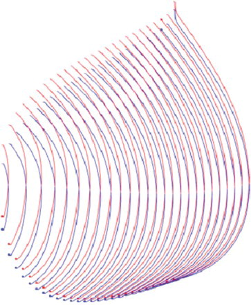
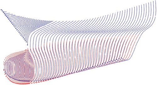
where rδxw(x) and rδzw(z) are the weighted translated x-coordinate and z-coordinate of the weighting function curve associated with the input parameter δxw, corresponding to the position of the mapping bulbous bow offsets. It is noted that if there are multiple weighting function curves, the second term of Equations (10) and (11) can be rewritten as the form of cumulative multiplying. Taking the transformation rules proposed above, the bulbous bow form can be fully parametrically varied to develop diverse hull shapes with different hydrodynamic properties. Figures and show bulbous bow offset transformations in the longitudinal x translation and the vertical z translation, respectively.
Figure 1. Longitudinal transformations of bulbous bow offsets (blue) compared to the original hull form (red).
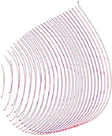
Figure 2. Vertical transformations of bulbous bow offsets (blue) compared to the original hull form (red).
Examples of the other three types of transformation of bulbous bow offsets are shown in Figures –.
Figure 3. Transverse transformations of bulbous bow offsets (blue) compared to the original hull form (red).
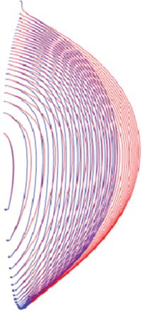
Figure 4. FP sectional area transformations of bulbous bow offsets (blue) compared to the original hull form (red).
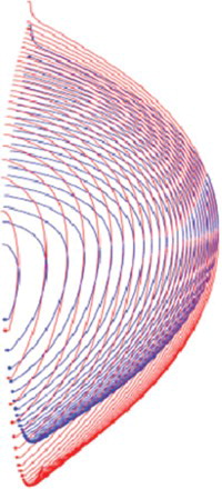
Figure 5. Fair transition transformations of foreship offsets (blue) compared to the original hull form (red).
3. Numerical solver
In the present study, the total calm water resistance Rt is used as an evaluation object during the hydrodynamic optimization design process, which is comprised of two main force components: the viscous resistance (1 + k)Rf caused by moving the ship through a viscous fluid and the wave-making resistance Rw caused by moving the ship across the surface of water and thus generating energy dissipation in the formation of waves. Specifically, the corresponding non-dimensionalized total resistance coefficient Ct can be formulated as
(12)
where (1 + k) is the form factor and the value is determined from the ship–model tests performed by the SSSRI/MARIN Joint Venture. Cf denotes the frictional resistance coefficient, which is given by the ITTC 1957 model–ship correlation line formula
(13)
(14)
where Rn is the Reynolds number, U is the ship speed, LWL is the length of the waterline and v is the coefficient of the kinematic viscosity of the fluid.
The wave-making resistance coefficient Cw is estimated using the Rankine source panel method with non-linear free-surface boundary conditions. From the viewpoint of potential flow theory, the flow is postulated to be incompressible, inviscid and irrotational. Considering a ship navigating on calm water with a steady forward speed U, with the Cartesian coordinate system fixed on the ship – so that the x-axis points from the bow to the stern and the y-axis extends to starboard on the undisturbed free surface, and the z-axis is vertically upwards – the total velocity potential φ subject to the Laplace equation in the fluid computational domain is
(15)
The total velocity potential φ is composed of the double-body velocity potential Φ and the perturbed velocity potential ϕ with the free surface effect. Together, three boundary conditions should be meditated.
3.1. The hull boundary condition
The fluid should not penetrate the hull surface and there is no velocity normal component into or away from the hull surface:
(16)
where
is the unit outward normal vector of the hull surface and is represented by
= (nx, ny, nz).
3.2. The free-surface condition
The kinematic and dynamic boundary conditions on the free surface can be obtained by the equations for the velocity potential φ and the position of the free surface elevation η:
(17)
(18)
where ∇φ = (φx, φy, φz), the subscripts denote the partial derivatives and g is the gravitational acceleration. Eliminating η from Equations (17) and (18), we obtain the combined non-linear free-surface condition
(19)
3.3. The radiation condition
The free-surface waves vanish upstream of the disturbance, i.e., the velocity potential should be equal to the incoming velocity potential where the infinity distance from the ship approaches
(20)
The Rankine source panel method by the iteration procedure can be employed to solve the simultaneous Equations (19) and (20), which are non-linear in terms of the free-surface problem. Once the velocity potential φ is resolved, the free-surface wave elevation η can be obtained by Equation (18). In addition, through the instrumentality of the Bernoulli equation, the pressure coefficient Cp at each panel can be defined as
(21)
where Fn is the Froude number with the expression
. Hence, the wave-making resistance coefficient Cw can be solved by the integral calculus of the pressure throughout the wetted hull surface S and formulated as
(22)
When each resistance coefficient component is obtained, the total calm water resistance Rt can then be determined by Rt = 0.5ρU2SCt, where ρ is the density of the fluid.
4. Optimization strategy
The optimization algorithm plays a vital role in evaluating the objective function for hull optimization and providing optimized design variables for the next hull form improvements. In this study, the NSGA-II is used as the hydrodynamic optimization strategy for searching for the optimal hull form with a minimal ship total resistance taking into account multiple load conditions. Contrary to classic GAs or other modified optimization methods, the NSGA-II (Deb et al., Citation2000) is an important improvement on the fast non-dominated sorting method, reducing the computational complexity O(mN3) to the most O(mN2) computations, density estimation and crowded comparison operator without artificially specifying the sharing parameter σshare.
4.1. The fast non-dominated sorting method
The fast non-dominated sorting method is implemented in such way that for a population P, each individual p possesses two entities Sp and np, which are the set of individuals dominated by the individual p and the number of individuals that dominate the individual p, respectively. All of the individuals are searched for in terms of np=0 and these are put in a list F1 which is assigned the corresponding non-dominated rank irank. Next, each member q in the set Sp of every individual p in the list F1 is examined, and its nq count is decremented by one so that if nq−1 = 0, the individual q is the non-dominant individual in Sp and classified into another set Q with the ungraded non-dominated sequence number. This process continues until all individuals are graded.
4.2. Density estimation and the crowded comparison operator
In order to maintain the diversity of a population, the NSGA-II employs the technology of density estimation which refers to the crowding distance id, that is, the size of the largest cuboid enclosing the point i without including any other point in the population, and without using fitness sharing and niche technology because of being in need of an artificially-specified sharing parameter. Figure depicts the crowding distance of the ith individual in its front list (marked with solid circles) and the average side-length of the cuboid (shown with a dashed box).
Figure 6. The crowding distance of the ith individual.
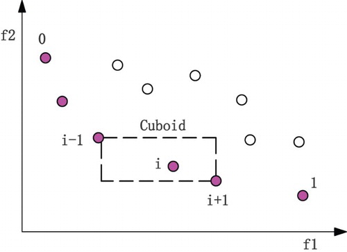
As can be seen from Figure , the feasible solutions are concentrated around an individual as its crowding distance id is small. Therefore, the crowded comparison operator is adopted to ensure that the algorithm can converge to a uniform distribution of Pareto-optimal front and a diverse population. The specific implementation is that for the random two individuals i, j equipped with two attributes – non-domination rank irank, jrank and crowding distance id, jd – if the conditions irank<jrank or irank=jrank but id<jd meet, then the individual i is preferred.
4.3. Algorithm flow
In the NSGA-II algorithm, an elitist strategy is employed which brings excellent individuals into the next generation by combining parent populations and child populations and reforming these individuals with the help of a fast non-dominated sorting method and crowded comparison. Taking into consideration the remarkable improvement resulting from this process, the NSGA-II algorithm flow is shown in Figure .
Figure 7. Flow chart for the NSGA-II.
5. Applications for full ship hydrodynamic optimization
In this article, a large container ship (LPP=286 m) with a bulbous bow that contributes to reducing the ship resistance is selected as the original hull, and the hydrodynamic optimization design tools described in the previous sections are applied in order to determine optimal hull bulbous bow forms for minimum total resistance taking into account multiple operating conditions.
5.1. Hydrodynamic analysis and experimental validation of the original hull
For effectively evaluating the objective of the study, the numerical solver discussed above is first validated by its application to the prediction of total resistance for the large container ship with the corresponding ship model test carried out by the SSSRI/MARIN Joint Venture. The original principal hull form characteristics under different conditions are presented in Table , and the hull offsets are drawn in isometric (ISO) view in Figure . Figures – show pictures of the ship model and a close-up view of the bulbous bow and calm water model tests under design conditions and scantling conditions.
Figure 8. ISO view of hull offsets.
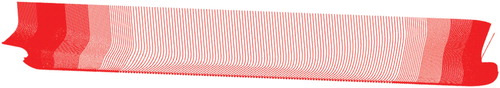
Figure 9. Side view of the foreship model.
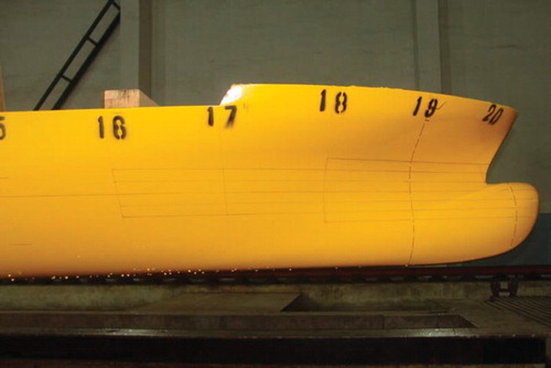
Figure 10. The bulbous bow of the ship model.
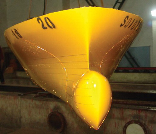
Figure 11. The ship model test at design draft.
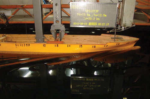
Figure 12. The ship model test at scantling draft.
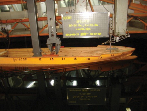
Table 1. Principal characteristics of the full ship and model for design and scantling drafts.
In Table , the computed total resistance of the original hull is compared with its experimental results for the case with Fn=0.183 (Froude number) for both design draft and scantling draft. Table presents a comparison of the computational results and experimental data for the total resistance for different Froude numbers under the condition of scantling draft. It can be seen that the results of the numerical calculations are in good agreement with the test data, as all the relative errors δe are less than 1% (bias errors within 1%) under different operating conditions. The effectiveness of the numerical solver proposed in this study is thus validated and can be integrated into the hydrodynamic optimization design process.
Table 2. Comparison of total resistance for numerical calculations and experimental results for design and scantling drafts.
Table 3. Comparison of total resistance for numerical calculations and experimental results for different Froude numbers.
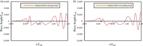
Figure shows the numerical results of wave contours on the free surface under the condition of Fn=0.183 for design draft and scantling draft. We also list the calculated longitudinal wave cut profiles at y/L = 0.1 for different x/L locations in the case of Fn=0.183 for the two draft conditions in Figure . It is observed that the amplitude of wave cut profiles of the original hull at the stem region the of design draft is greater than that of scantling draft (Figure ), which may be caused by the effect of the above-water bulbous bow under the condition of a smaller draft.
Figure 13. Wave contours at Fn=0.183 for (a) design draft and (b) scantling draft.
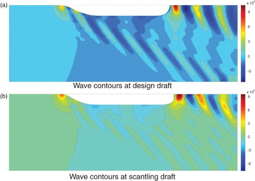
Figure 14. Longitudinal wave cut profiles of the original hull on y/LPP=0.1 at Fn=0.183 for (a) design draft and (b) scantling draft.
5.2. Integrated implementation of the hull bulbous bow optimization
A hydrodynamic optimization design surrounding the original container ship is presented in this subsection. Container ships frequently operate under multiple load conditions – such as the design, ballast, and scantling draft conditions – at a wide range of speeds, which should all be taken into account for better hydrodynamic performance. With the above in mind, the main focus of the paper is to optimize the hull bulbous bow form in order to achieve superior integrated performance in terms of the design and scantling draft conditions across multiple speeds, accepting the possibility that this optimization may result in a slight performance decrease under the contract design condition.
5.2.1. Optimization implementation
5.2.1.1. Objective function
When processing the optimization design, the total resistance is selected as a typical criterion for the evaluation of ship hydrodynamic performance. As multiple operating conditions are considered in this study, a mixed-objective function is introduced that represents the weighted sum of the total resistance ratios under the design and scantling draft conditions across multiple speeds for the final deterministic optimizations. The final expression is formulated as
(23)
where n is the number of Froude numbers Fn for the design draft and n = 3 with Fn=0.164, 0.183, 0.212, m is the number of Froude numbers Fn for the scantling draft and m = 3 with Fn=0.173, 0.183, 0.193, α and β are the weighting parameters of their corresponding conditions obtained from the representative operational profile in the contract, Rt is the total resistance of the new variant and Rt0 is the total resistance of the original hull. It is noted that the case of Fn=0.212 for the design draft is the contract design condition.
5.2.1.2. Design variables
As illustrated in subsection 2.2, the bulbous bow yields five types of distortion transformation, so the corresponding design variables are determined to develop diverse ship bulbous bow forms. The specific definition of the design variables are
where dx1 controls the longitudinal translation of the bulb length, dy1 and dy2 control the transverse translation of the bulb fullness, dy3 and dy4 control the corresponding fair transition translation of the ship main forepart, dz1 controls the vertical translation of the bulb tip, and dz2 controls the sectional area translation of the bulb at the FP position.
5.2.1.3. Constraint conditions
The constraint conditions on the design variables presented above are listed as follows:
where λ is the ship model scale ratio in Table . The variation of hull displacement and wet surface area are |∇/∇0−1|<1% and |S/S0−1|<1%, respectively.
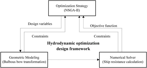
For comprehension of the separate-functional methodology proposed above, the final complete integrated process of the hydrodynamic optimization design framework is presented in Figure .
Figure 15. The integrated process for the hydrodynamic optimization design framework.
5.2.2. Optimization results
During the optimization process, the Sobol algorithm using the design of experiments (DoE) method is adopted to develop a systematic design space exploration, which is used to detect reasonable starting points for deterministic optimization. Then the NSGA-II is employed with a population number of 20 in each generation and a generation number of 20 to search for the optimal hull bulbous bow form under the objective function and all the necessary constraints. The optimization cycle was conducted on an Intel Core(TM) Quad CPU @ 3.90 GHz, which took almost 115 hours to obtain the final optimized results. Through analysis of the optimization design, the convergence history for the objective function considering all loads conditions is shown in Figure .
Figure 16. Convergence history plot of the objective function under all load conditions.
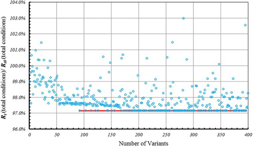
As can be seen, the convergence solution on the lower boundary in Figure (the red line), which is the corresponding final optimized hull bulbous bow, results in a decrease of 2.845% in the total resistance under multiple operating conditions. Table presents the comparison of the results of resistance performance for two draft conditions between the optimized hull and the original hull, which show considerable reductions in resistance under multiple load conditions though a small increment exists. The body plans and the buttock lines of the final optimized hull and the original hull are presented in Figure , from which it can be seen that the optimized bulbous bow profile varies from the conventional container ship at high speed for comprehensive economic benefits under multiple operating conditions.
Figure 17. Comparison of the optimized forebody hull form (blue) and original hull form (red) for (a) the body plans and (b) the buttock lines.
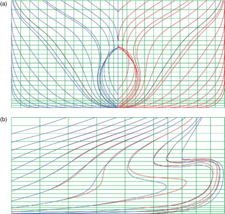
Table 4. Resistance results for optimized and original hulls for design and scantling drafts.
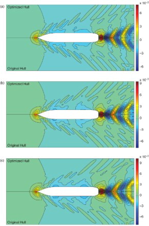
Calculated wave profiles at different Froude values for the two draft conditions comparing the optimized and original hulls are shown in Figure . It can be observed that the amplitude of waves for the optimized hull has been decreased under multiple conditions of Froude numbers for the design and scantling drafts, indicating a reduction in resistance compared to the original hull. In Figures and , the wave contours for the design and scantling drafts respectively are compared for the optimized and original hulls for multiple Froude numbers. It can be seen that the maximum amplitudes of the first wave in the bulbous bow region of the optimized hull are less than those of the original hull for both the design and scantling drafts throughout the range of Froude numbers, illustrating that the disturbed wave energy has been weakened due to the optimized bulbous bow form. There are diverse vortices located in the stern region; for each draft case, the maximum wave crest and trough around the hull swell with the Froude numbers increasing markedly.
Figure 18. Comparison of wave profiles between the optimized and original hull for (a) the design draft at Fn=0.164, (b) the design draft at Fn=0.183, (c) the design draft at Fn=0.212, (d) the scantling draft at Fn=0.173, (e) the scantling draft at Fn=0.183, and (f) the scantling draft at Fn=0.193.
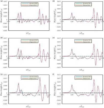
Figure 19. Comparison of the wave contours between the optimized and original hull for the design draft at (a) Fn=0.164, (b) Fn=0.183, and (c) Fn=0.212.
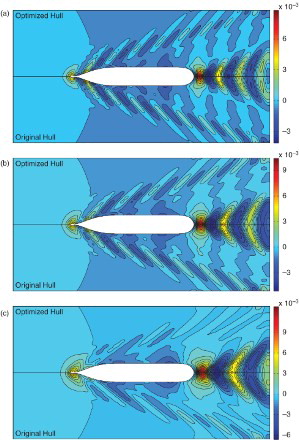
Figure 20. Comparison of the wave contours between the optimized and original hull for the scantling draft at (a) Fn=0.173, (b) Fn=0.183, and (c) Fn=0.193.
6. Conclusions
A hydrodynamic optimization design methodology for the ship bulbous bow form taking into account multiple operating conditions including design and off-design conditions across a wide range of speeds has been implemented and applied. The transformation of the hull form is based on the parametric form approach by employing a fairness-optimized B-Spline form parameter curve – namely the F-Spline parametric curve – which results in form design parameters for use in the optimization system based on the NSGA-II. The minimum total resistance taken as the objective function was evaluated by a combination of the ITTC 1957 model–ship correlation formula and the potential flow Rankine source panel method. Validation studies were conducted for the original ship through a comparison of the results obtained by this numerical solver and the experimental measurements, which show satisfactory agreement under multiple operating conditions.
The systematic optimization methodology proposed has been applied to a full large container ship and a design variant with optimal performance is identified. The optimization results show a decrease of 2.845% in the total resistance of the optimal hull bulbous bow taking into account multiple operating conditions, which is comprehensively analyzed through a comparison of wave profiles and contours for the original and optimized hulls. The fact that this optimized hull bulbous bow is identified as the best configuration under multiple operating conditions consequently proves the importance of including off-design conditions, highlighting the disadvantage of designing and optimizing a ship for a single design condition in early stages of ship design, as this may lead to a poorer performance under other load conditions. Since the main consideration of this paper is the improvement of total calm water resistance performance across multiple navigational conditions, characteristics of the hull that occur under practical oceanic conditions are not taken into account, leaving scope for further optimization in future work which takes into account other factors and conditions.
In summary, the present study demonstrates an effective and robust integrated approach for the hydrodynamic optimization of ship (or specifically bulbous bow) design which takes into account multiple realistic operating conditions and offers constructive assistance for designers when attempting to make decisions which lead to superior performance through optimized designs.
Acknowledgements
We gratefully acknowledge CIMC (Shanghai) Ocean Engineering Research Institute Co., Ltd. for providing funding for the experimental program implemented by the SSSRI/MARIN Joint Venture. The authors are grateful to the reviewers for their comments and suggestions for improving the paper.
Disclosure statement
No potential conflict of interest was reported by the authors.
Additional information
Funding
References
- Abt, C., Harries, S., Heimann, J., & Winter, H. (2003). From redesign to optimal hull line by means of parametric modeling. 2nd International on Computer Applications and Information Technology in the Marine Industries (COMPIT 2003), Hamburg, Germany, 444–458.
- Birk, L., & Harries, S. (Eds.). (2003). OPTIMISTIC—optimization in marine design. Berlin: Mensch & Buch Verlag.
- Campana, E.F., Peri, D., Tahara, Y., & Stern, F. (2006). Shape optimization in ship hydrodynamics using computational fluid dynamics. Computer Methods in Applied Mechanics and Engineering, 196, 634–651.
- Chau, K. W., & Wu, C. L. (2010). A hybrid model coupled with singular spectrum analysis for daily rainfall prediction. Journal of Hydroinformatics, 12(4), 458–473.
- Chen, P. F., & Huang, C. H. (2004). An inverse hull design approach in minimizing the ship wave. Ocean Engineering, 1, 1683–1712.
- Choi, H. J., Park, D. W., & Choi, M. S. (2015). Study on optimized hull form of basic ships using optimization algorithm. Journal of Marine Science and Technology – Taiwan, 23(1), 60–68.
- Deb, K., Agrawal, S., Pratap, A., & Meyarivan, T. (2000). A fast elitist non-dominated sorting genetic algorithm for multi-objective optimization: NSGA-II. Lecture notes in computer science, 1917, 849–858.
- Dejhalla, R., Mrsa, Z., & Vukovic, S. (2002). A genetic algorithm approach to minimum ship wave resistance problem. Marine Technology, 39(3), 187–195.
- Grigoropoulos, G. J., & Chalkias, D. S. (2010). Hull-form optimization in calm and rough water. Journal of Computer-Aided Design, 42(11), 977–984.
- Grigoropoulos, G. J., Chalkias, D. S., & Tikkos, C. (2004). Multi-objective hull form optimization of high-speed vessels. In V. Beltram (Ed.), HIPER '04 (pp. 264–276). Rome: INSEAN.
- Harries, S. (1998). Parametric design and hydrodynamic optimization of ship hull forms. Ph.D. Thesis, Institut fur Schiffs-und Meerestechnik, Technische Universitat Berlin, Germany; Berlin: Mensch & Buch Verlag.
- Harries, S. (2007). Friendship systems: Hydrodynamic optimization of the DSME 60 K LPG Carrier, FS-Report 175–02-01.
- Harries, S., & Abt, C. (1998). Parametric curve design applying fairness criteria. In: International Workshop on Creating Fair and Shape-Preserving Curves and Surfaces. Berlin: Teubner.
- Harries S., Abt, C., & Hochkirch, K. (2004). Constraint management for marine design applications. In: International symposium on practical design of ships and other floating structures (PRADS 2004), Lübeck-Travemünde, Germany, September 2004.
- Harries, S., Valdenazzi, F., Abt, C., & Viviani, U. (2001). Investigation on optimization strategies for the hydrodynamic design of fast ferries, FAST’01, Southampton.
- Hinatsu, M. (2004). Fourier NUBS method to express ship hull form. Journal of Marine Science and Technology, 9, 43–49.
- Kang, J. Y., & Lee, B. S. (2010). Mesh-based morphing method for rapid hull form generation. Comput Aided Des, 42, 970–976.
- Kim, H., & Yang, C. (2010). A new surface modification approach for CFD-based hull form optimization. Journal of Hydrodynamics, Ser. B, 22(5), 520–525.
- Lee, Y. S. (2003). Trends validation of CFD predictions for ship design purpose. Ph.D. Thesis, Institut fur Schiffs-und Meerestechnik, Technische Universitat Berlin, Germany.
- Lee, Y. S., Kim, S. Y., & Kang, K. T. (1995). Hull form generation by using TSK fuzzy model. Fuzzy logic and its application, information science and intelligence systems.
- Liang, Y., Cheng, X. Q., Li, Z. N., & Xiang, J. W. (2011). Robust multi-objective wing design optimization via CFD approximation model. Engineering Applications of Computational Fluid Mechanics, 5(2), 286–300.
- Li, M. C., Si, Q., Liang, S. X., & Sun, Z. C. (2014). Multiple objectives for genetically optimized coupled inversion method for jet models in flowing ambient fluid. Engineering Applications of Computational Fluid Mechanics, 8(1), 82–90.
- Lowe, T. W., & Steel, J. (2003). Conceptual hull design using a genetic algorithm. Journal of Ship Research, 47(3), 222–236.
- Maisonneuve, J. J., Harries, S., Marzi, J., Raven, H. C., Viviani, U., & Piippo, H. (2003). Toward optimal design of ship hull shapes. In: 8th international marine design conference, IMDC03, Athens.
- Mancuso, A. (2006). Parametric design of sailing hull shapes. Ocean Engineering, 33, 234–246.
- Nowacki, H., & Kaklis, P. D. (Eds.). (1998). Creating FAIR and SHAPE preserving curves and surfaces. Stuttgart: B.G. Teubner.
- Pérez, F., & Clemente, J. A. (2011). Constrained design of simple ship hulls with B-spline surfaces. Computer-Aided Design, 43, 1829–1840.
- Pérez, F., Suárez, J. A., Clemente, J. A., & Souto, A. (2007). Geometric modeling of bulbous bows with the use of non-uniform rational B-Spline surfaces. Journal of Marine Science and Technology, 12, 83–94.
- Pérez, F., Suárez-Suárez, J. A., & Fernández-Jambrina, L. (2006). Automatic surface modeling of a ship hull. Computer-Aided Design, 38, 584–594.
- Peri, D., Rossetti, M., & Campana, E. F. (2001). Design optimization of ship hulls via CFD techniques. Journal of Ship Research, 45(2), 140–149.
- Ping, Z., Xiang, Z. D., & Hao, L. W. (2008). Parametric approach to design of hull forms. J Hydrodyn, 20(6), 804–810.
- Saha, G. K., Suzuki, K., & Kai, H. (2004). Hydrodynamic optimization of ship hull forms in shallow water. Journal of Marine Science and Technology, 9, 51–62.
- Saha, G. K., Suzuki, K., & Kai, H. (2005) Hydrodynamic optimization of a catamaran hull with large bow and stern bulbs installed on the center plane of the catamaran. Journal of Marine Science and Technology, 10, 32–40.
- Sarioz, E. (2006). An optimization approach for fairing of ship hull forms. Ocean Engineering, 33(16), 2105–2118.
- Shereena, S. G., Vengadesan, S., Idichandy, V. G., & Bhattacharyya, S. K. (2013). CFD study of drag reduction in axisymmetric underwater vehicles using air jets. Engineering Applications of Computational Fluid Mechanics, 7(2), 193–209.
- Srinivas, N., & Deb, K. (1994). Muiltiobjective optimization using nondominated sorting in genetic algorithms. Evolutionary computation, 2(3), 221–248.
- Suzuki, K., Kai, H., & Kashiwabara, S. (2005). Studies on the optimization of stern hull-form based on a potential flow solver. Journal of Marine Science and Technology, 10(2), 61–69.
- Tahara, Y., Peri, D., Campana, E. F., & Stern, F. (2008). Computational fluid dynamics-based multiobjective optimization of a surface combatant using a global optimization method. Journal of Marine Science and Technology, 13 (2), 95–16.
- Tahara, Y., Stern, F., & Himeno, Y. (2004). Computational fluid dynamics based optimization of a surface combatant. Journal of Ship Research, 28(4), 273–287.
- Tahara, Y., Wilson, R. V., Carrica, P. M., & Stern, F. (2006). RANS simulation of a container ship using a single-phase level-set method with overset grids and the prognosis for extension to a self-propulsion simulator. Journal of Marine Science and Technology, 11, 209–228.
- Taormina, R., & Chau, K. W. (2015). Data-driven input variable selection for rainfall–runoff modeling using binary-coded particle swarm optimization and extreme learning machines. Journal of Hydrology, 529, 1617–1632.
- Valdenazzi, F., Harries, S., Viviani, U., & Abt, C. (2002). Seakeeping optimisation of fast vessels by means of parametric modeling, HSMV02, Naples.
- Valorani, M., Peri, D., & Campana, E. F. (2003). Sensitivity analysis techniques for design optimization ship hulls. Optimization and Engineering, 4(4), 337–364.
- Wang, W. C., Chau, K. W., Xu, D. M., & Chen, X. Y. (2015). Improving forecasting accuracy of annual runoff time series using ARIMA based on EEMD decomposition. Water Resources Management, 29(8), 2655–2675.
- Wu, C. L., Chau, K. W., & Li, Y. S. (2009). Methods to improve neural network performance in daily flows prediction. Journal of Hydrology, 372(1), 80–93.
- Yang, C., Fuxin, H., & Kim, H. (2015). Hydrodynamic optimization of a triswach. Journal of Hydrodynamics, Ser. B, 26(6), 856–864.
- Yang, C., Fuxin, H., & Noblesse, F. (2013). Practical evaluation of the drag of a ship for design and optimization. Journal of Hydrodynamics, Ser. B, 25(5), 645–654.
- Yasukawa, H. (2000). Ship form improvement using genetic algorithm. Ship Technology Research, 47(1), 35–44.
- Zhang, B. J. (2012). Research on optimization of hull lines for minimum resistance based on Rankine source method. Journal of Marine Science and Technology, 20(1), 89–94.
- Zhang, B. J., Kun, M., & Ji, Z. S. (2009). The optimization of the hull form with the minimum wave making resistance based on Rankine source method. Journal of Hydrodynamics, Ser. B, 21(2), 277–284.
- Zhang, J., & Chau, K. W. (2009). Multilayer ensemble pruning via novel multi-sub-swarm particle swarm optimization. Journal of Universal Computer Science, 15(4), 840–858.
- Zhang, S., & Chau, K. W. (2009). Dimension reduction using semi-supervised locally linear embedding for plant leaf classification. In Emerging intelligent computing technology and applications. Berlin: Springer, 949–955.