
 ?Mathematical formulae have been encoded as MathML and are displayed in this HTML version using MathJax in order to improve their display. Uncheck the box to turn MathJax off. This feature requires Javascript. Click on a formula to zoom.
Abstract
Idling power loss suppression techniques of hydraulic retarders in non-braking operating conditions are of great significance to improve vehicle driving efficiency. Most proposed idling power loss suppression devices require auxiliary operating parts, take up a lot of space and increase the load on the vehicle. In this study, the plunger spoiler was optimized with a non-smooth bionic surface for improved performance and compactness. Hydraulic retarders with traditional smooth spoilers and different bionic non-smooth surface spoilers were simulated and tested to investigate the effects of bionic non-smooth surfaces on idling performance. The numerical results indicated that the bionic spoilers could disturb the fluid flow, lower the blade pressure and increase the internal energy dissipation, leading to reduced rotor drag and lower idling power loss. The mechanism of drag reduction on rotor and efficiency improvement was discussed. The experimental data showed that bionic non-smooth surface spoilers reduced idling torque by 11.7% at a rotor speed of 3000 r/min, compared to the traditional smooth surface spoilers. In conclusion, the hydraulic retarder with an optimized bionic surface spoiler is able to reduce idling power loss and improve transmission efficiency effectively.
1. Introduction
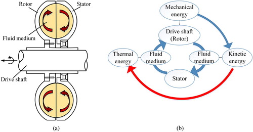
A hydraulic retarder is an effective auxiliary braking device which is widely applied in heavy-duty vehicles thanks to its advantages of high emergency braking torque and continuous stable braking with flexible anti-hunt action compared to mechanical brakes. It provides auxiliary braking torque when transmission oil is fed into the chamber. The transmission oil is driven by the rotor and impacts the stator. By doing this, the rotor’s mechanical energy is transformed into the oil’s thermal energy, and the braking torque is generated (Figure ) (Yan, Zou, & Wei, Citation2011).
Figure 1. Sketches showing the principles of the hydraulic retarder: (a) structure; (b) energy flow.
In non-braking operating conditions, the control system discharges oil from the hydraulic retarder and fills the chamber with air, which could lead to idling power loss and lower vehicle driving efficiency because of undesirable air drag torque. The hydraulic retarder braking torque is proportional to the square of the rotational speed, so the idling power loss increases drastically with increasing rotor rotating speed in non-braking conditions. Therefore, reducing the idling power loss becomes a significant research subject.
Various forms of idling loss inhibition devices have been proposed. A set of clutch devices was designed to reduce drag loss by disconnecting the hydraulic retarder from the drive shaft (CN Patent No. 200810020498.2, Citation2008). This set-up needed an extra gear pair and operating device. G. Wei (Citation2011) put forward a vacuum reduction control system to reduce idling loss by reducing air pressure or density in the working chamber. However, the system consisted of a vacuum pump, solenoid valve, pressure sensor, suction pipe and control device, which would require a lot of space. Guo and Yan (Citation2003) and C. Wu and Xu (Citation2012) designed hydraulic retarders with valve plates in the impeller to inhibit idling air loss by reducing the flow area diameter. Wang, Wang, Fu, and Xiao (Citation2014) designed a plunger-type turbulent flow device to inhibit idling loss. The plunger device included a spoiler, which would disturb the air flow and reduce idling loss. Among these idling loss inhibition devices, the plunger-type device with spoiler is effective and compact, and does not affect the normal braking process (W. Wei, Mu, & Yan, Citation2015). Therefore, the plunger-type device is investigated in this study. To improve the spoiler performance, this article presents a non-smooth bionic surface spoiler and the surface structure was optimized for lower idling loss. The effect of non-smooth surfaces was investigated by means of computational fluid dynamics (CFD) studies and validated through test data.
Inspired by the non-smooth skin drag reduction and wear resistance properties of plants and animals, such as sharks, dung beetles, earthworms and lotus leaves (Carpenter, Citation1989; Cong et al., Citation1992; Dinkelacker, Nitschke-Kowsky, & Reif, Citation1987; Gray, Citation1936; Yang & Ren, Citation2003), the biological epidermal structure has been widely applied in numerous fields, such as rotary fluid machinery drag reduction (C. Liu, Citation2015; Ren, Peng, Chen, Zhao, & Wang, Citation2007), aircraft wings and exterior surface design (W. Li, Citation2009; S. Zhang & Hu, Citation2015), superhydrophobic surface and material design (An et al., Citation2019; E. Liu et al., Citation2017; C. Liu, Zhu, Li, & Liang, Citation2019) and improvement of sealing performance (X. Chen, Zeng, & Chen, Citation2019; Zeng, Zhou, & Ma, Citation2018). The bionic structure has a great influence on the near-surface flow characteristics. The drag reduction mechanism can be revealed by flow-field simulations (Gu et al., Citation2014; Mezghani, Demirci, Zahouani, & Mansori, Citation2012; Tian, Ren, & Liu, Citation2007). It was found that the bionic structure could reduce the flow velocity around the surface and change the vortex-induced vibration. Scholars have investigated the effect of shark skin denticle geometry on windbreak fence design (Bajsanski, Stojakovic, Tepavcevic, Jovanovic, & Mitov, Citation2017) and the effect of bionic attachments on piezoelectric energy harvester improvement (Jin, Li, Wang, & Zhang, Citation2019). Experimental investigations have been conducted on a new type of non-uniform surface cylinder inspired by harbor seal vibrissae to reduce aerodynamic forces and suppress vortex shedding (W. Chen, Min, Gao, Guo, & Li, Citation2018). Common bionic structures are pit, convex, groove and ridge structures (Hu, Song, & Liu, Citation2011; M. Liu et al., Citation2019; Z. Liu & Dong, Citation2006; Pan & Huang, Citation2010; Song, Lin, Liu, & Zhou, Citation2017; L. Wu et al., Citation2018; Zhou, Zhai, Ding, & Wang, Citation2017). Considering the structure and manufacturing feasibility of the spoiler being investigated, pit and groove structures were applied in this paper.
CFD techniques have been widely used in fluid machinery design and analysis. Numerical simulation has been used to research wind pressure distributions on and around various squared-shaped tall buildings and the effects of building dimensional variation on wind pressure distribution (Mou, He, Zhao, & Chau, Citation2017). Many problems have been studied by analyzing microscopic hydrodynamic parameters, such as nanofluid flow inside a root canal (Ghalandari, Koohshahi, Mohamadian, Shamshirband, & Chau, Citation2019), prediction of a multi-input bubble column reactor (Mosavi, Shamshirband, Salwana, Chau, & Tah, Citation2019) and research on nanofluidic thermosyphon heat exchangers (Ramezanizadeh, Nazari, Ahmadi, & Chau, Citation2019). Numerical simulation has also applied in the simulation of a dual-fuelled diesel engine to analyze the cylinder pressure (Akbarian et al., Citation2018).
Therefore, the hydraulic retarder idling characteristics have been simulated by CFD. By investigating the drag reduction efficiency with regard to varying bionic non-smooth surfaces, this paper aims to determine the best idle power loss suppression structure. Impeller flow passage models with conventional smooth spoiler devices and bionic non-smooth surface spoiler devices were established. The idle power loss performance, velocity vector, pressure and wall shear stress were investigated, and the mechanism and effect of bionic surface structures on idling power loss reduction were studied.
2. Simulation model
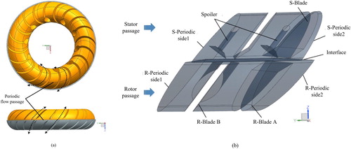
A vehicular hydraulic retarder was investigated and spoiler devices were installed on the outer loop of the stator. The full flow passage model is shown in Figure (a). The spoiler device is composed of the cavity and the spoiler, which is a disk with conical profile. The top surface of the spoiler is vertical to the stator inlet direction and the central axis of the spoiler locates in the middle of the adjacent blades. There are two types of blade in the rotor: an ordinary blade, which is defined as R-Blade A, and a blade with an inlet, defined as R-Blade B. This paper was designed to study the characteristics of the hydraulic retarder without oil filling, so the blade was simplified by ignoring the inlet and the outlet structures. The periodic flow passage model with two blades and two spoiler devices was adopted for the simulation (Figure b).
Figure 2. Hydraulic retarder flow passage model: (a) full flow; (b) periodic flow.
3. Non-smooth bionic structure selection design
Bumps are randomly distributed on the head and carapace surface of the dung beetle, which effectively reduce the adhesion and the friction coefficient. Previous research studied the skin structure and mechanisms for reducing resistance in the dung beetle. Different parts of the dung beetle’s surface had different geometric non-smooth morphology. Convex hull structures were found in the dung beetle’s head and claws, while elliptical pits were found on the dung beetle’s carapace surface. The study showed that the body of the dung beetle reduced soil adhesion via non-smooth surface morphology (Ren & Cong, Citation1992).
In turbulent flow, the loss of kinetic energy increases with an increasing boundary layer thickness. Bionic non-smooth surface drag reduction is based on the reduction of the boundary layer’s thickness, so that the flow separation in the boundary layer is delayed or suppressed (Tian, Citation2005). Therefore, the height of the bionic non-smooth unit can be estimated according to the boundary layer thickness. As the flow separation usually occurs in the logarithmic law range, the following formula is used to estimate the height of the non-smooth unit: y + < 30–70, y < 0.2δ, where δ is boundary layer thickness and y is the height of a non-smooth unit (Z. Li & Tian, Citation2010). The spoiler diameter was 19.5 mm. Based on preliminary simulation results, the relative air velocity within the whole range of transmission ratios was calculated as 1.31–13.82 m/s (S. Li, Citation2016). The thickness of the boundary layer was calculated via the following equations (Schlichting, Citation1991):
(1)
(1) where
is average length, the diameter of the spoiler is 19.5 mm, Re is the Reynolds number, and the kinematic viscosity of air is
.
The range of the height of the non-smooth unit is 0.13–0.28 mm; thus, a height of 0.2 mm was chosen. Two non-smooth structures – pits and grooves – were studied, considering the processing difficulty and application. The radius of the pit is 0.2 mm and the height of the V-shaped groove is 0.2 mm. The sectional views of the bionic units are shown in Figure . Because the spoiler is circular in structure, to avoid the influence of orthogonal distribution form on directivity, the distribution of the bionic units is chosen as circumferential (Figure ).
Figure 3. Section structure views of the bionic unit: (a) pit section; (b) groove section.
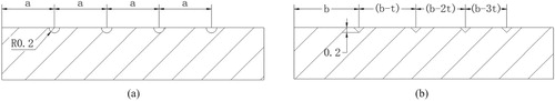
Figure 4. Distributions of bionic units: (a) Model A; (b) Model B; (c) Model C.
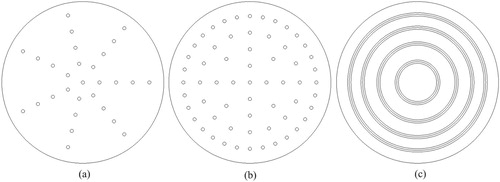
In different periodic flow passages, the direction of incoming flow may deviate and the circular spoiler may rotate around the central axis under the impact of oil pressure during braking conditions. Thus, there is no guarantee that the fluid will flow at the same angle relative to the surface of the spoiler, so the effect on the spoiler at different positions will be different. Therefore, the circumferentially distributed bionic units were adopted to avoid the directional effects of orthogonal distribution (Figure ). In Model A, the pits are distributed on concentric circles centered on the spoiler disk, and adjacent concentric circles are equally spaced. The number of pits on each concentric circle is the same. In Model B, the number of adjacent ring pits doubles from the center to the outer ring. In Model C, the circular grooves are distributed concentrically and the interval between adjacent grooves decreases by an equal difference from the inside to the outside.
4. Numerical simulation method
4.1. Grid generation
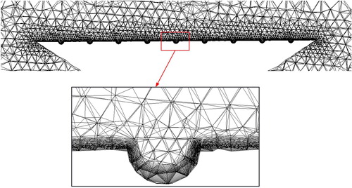
ANSYS ICEM was used to discretize the fluid flow with unstructured tetrahedral grids. As a result of the large difference between the bionic unit and the overall flow passage sizes, the grids near the bionic unit need to be refined.
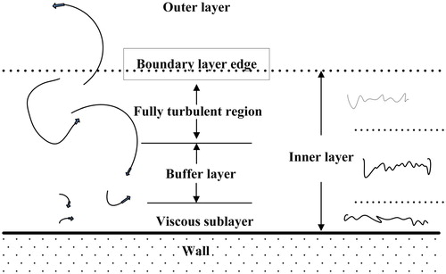
Figure shows a sketch of the structure of the boundary layer. In previous research (M. Liu, Citation2012), enhanced wall treatment and standard wall function had different requirements on the near-wall meshes. In this paper, the automatic wall function method was used to deal with the low Reynolds number fluid near the wall surface.
Figure 5. Structure of the boundary layer.
By Equation (Equation2(2)
(2) ), the distance from the first layer grid to wall was estimated (Fluent Inc., Citation2003):
(2)
(2) where
is kinematic viscosity, and
is a dimensionless distance from the first layer grid to the physical plane. It was reported that the k-ω mode requires
(Parker, Citation2004; C. Zhang, Citation2007). In this paper, shear stress transport (SST) k-ω mode was applied and
was guaranteed by a refined boundary mesh. The average frictional resistance coefficient
is calculated as follows:
(3)
(3) where
is wall surface friction velocity, and
is the velocity of fluid with stabilization. By combining Equations (Equation2
(2)
(2) ) and (Equation3
(3)
(3) ), the distance from the first grid layer to the wall can be expressed as:
(4)
(4) The average friction drag coefficient can be estimated by:
(5)
(5) Therefore, the distance between the first grid layer and the wall surface can be calculated. As the calculated first layer grid-to-wall distance varies within 0.0035–0.246 mm, 0.002 mm was used to make sure that the first layer grid was located in the viscous sublayer. Figure shows the mesh distribution of the boundary layer adjacent to the bionic surface.
Figure 6. Mesh distribution of the boundary layer.
4.2. Governing equation
Owing to the high speed of the rotor and intense interaction between the working medium and the components of the structure, the flow inside the hydraulic retarder is complex three-dimensional turbulent flow. Neglecting the heat transfer of the working medium, the flow is governed by the mass conservation equation and momentum conservation equation (X. Li, Yu, Cheng, & Miao, Citation2012; W. Wei, Li, Zou, & Yan, Citation2010), also known as the Navier–Stokes (N-S) equation. The tensor form of the mass conservation equation is as follows:
(6)
(6) where ρ is density, t is time, and
is the component of the velocity vector in
direction. The tensor form of the N-S equation can be expressed as:
(7)
(7) where
is Kronecker’s symbol, and
is volume force. For incompressible fluid with constant dynamic viscosity, the above formula can be simplified as:
(8)
(8)
4.3. Computational settings
ANSYS CFX software was used to conduct the steady-state simulation. The air ideal gas was used and the isothermal model was considered. The Reynolds number of the studied flow is in the order of 104–105, which means that it is a fully developed turbulent flow, so the SST turbulent model was selected, which takes into account the turbulent shear stress transfer with accurate prediction of boundary layer separation under a pressure gradient to capture tiny eddies. The boundary conditions were set according to the geometries and operating conditions of the impellers. The mixed plane theory was applied to exchange data between the rotor and the stator, and rotationally periodic boundaries were assumed on each side of the flow passage. Other surfaces were assumed to be no-slip rigid walls. Residuals of 1 × 10⁻⁶ for the flow-field parameters were used as the iteration convergence targets.
5. Simulation results and discussion
In this section, the torque characteristics and internal flow-field parameters of the hydraulic retarder obtained by numerical simulation are shown and analyzed. The influences of the bionic surface on velocity, pressure, shear stress and energy dissipation are discussed, and the idling loss reduction mechanism is analyzed.
5.1. Comparison of idling power loss performance
The idling torque characteristics with ordinary spoilers and three types of bionic surface spoiler in the hydraulic retarder are compared in Figure . The effect of the bionic surface in inhibiting idling loss is clearly reflected in the performance curves.
Figure 7. Idling power loss inhibition effects on external characteristics: (a) idling torques of contrast models; (b) torque reduction ratios of contrast models.
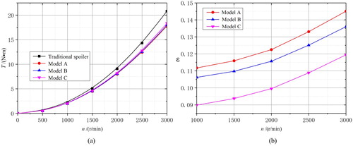
As the rotational speed increases, the torque of the hydraulic retarder increases gradually. It is clear that the application of a bionic non-smooth surface leads to lower idling torque than with the traditional spoiler, as shown in Figure (a). A dimensionless variable (i.e. the torque reduction ratio, ) is defined to quantify the torque reduction amplitude:
(9)
(9) where
is the torque of the retarder with a traditional spoiler, and
is the torque of the retarder with a bionic surface spoiler.
A higher drag reduction ratio indicates lower idling torque and better spoiler performance. Figure (b) shows the drag reduction ratio at different rotational speeds. As the rotational speed goes up, the drag reduction ratio increases gradually. The drag reduction ratios of Models A and B are higher than that of Model C at the same rotational speed. Therefore, pit bionic structures outperformed the groove bionic structure in terms of idling loss inhibition. The results showed that Model A yielded the best performance, which could reduce the idling loss by 14.5% at a speed of 3000 r/min.
5.2. Velocity distribution and energy dissipation analysis
5.2.1. Velocity vector
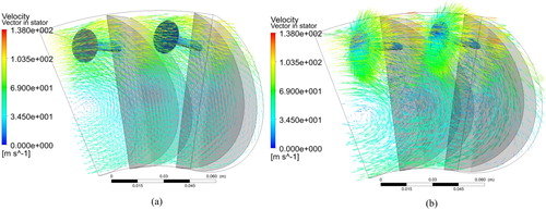
To analyze the relationship between the velocity vector and the idling power loss, the velocity distributions of the spoilers with and without bionic structure are compared, taking the traditional spoiler and Model B spoiler as examples.
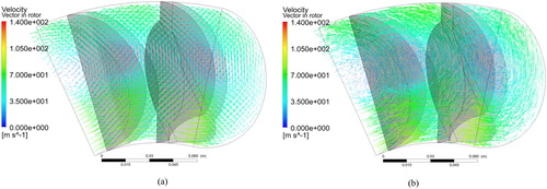
As shown in Figure , the fluid velocity vector in the stator without a bionic structure is more regular than that with the bionic surface spoiler. The non-smooth surface spoiler disordered the flow field in corresponding areas, leading to lower idling power loss. The velocity fields with two different spoiler structures are similar; however, the flow velocity around the non-smooth spoiler is higher than the velocity around the smooth spoiler. The flow velocity fields indicate that the bionic structure disturbs the flow field around it and the distribution of the flow field changes considerably.
Figure 8. Velocity vector distribution in stator with the rotor speed fixed to 3000 r/min: (a) with smooth surface spoiler; (b) with bionic surface spoiler.
In Figure , the rotor velocity vector is distributed more regularly in the smooth spoiler case, while it appears to be more complex in the bionic structure spoiler case. The flow state of the internal flow field determines the external characteristics. Comparing Figures and , the influence of the bionic structure on the rotor flow field is weaker than that on the stator. The velocity vector in the stator internal flow field with a bionic structure spoiler shows severe disturbance near the bionic structure, which interrupts the orderly cycle of flow and contributes to the idling loss inhibition.
Figure 9. Velocity vector distribution in rotor with the rotor speed fixed to 3000 r/min: (a) with smooth surface spoiler; (b) with bionic surface spoiler.
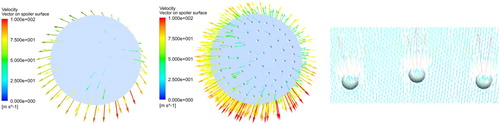
In Figure , the velocity vector distribution is similar in the two cases. However, the enlarged view of the velocity vector on the pit bionic surface of spoiler shows that there is abrupt change in the velocity vector when the air flows near the pit structure. At a low flow rate, the airflow remains attached to the pit surface, whereas the airflow detaches from the pit surface as the flow rate becomes higher and higher.
Figure 10. Velocity vector around the surface of the spoiler and enlarged view.
5.2.2. Internal energy dissipation
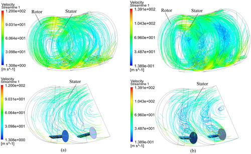
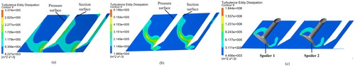
Turbulence is a complex three-dimensional motion, where vortices of different scales and shapes evolve. Large-scale vortices transform into small-scale vortices until they disappear, and the energy dissipates with this process. The velocity streamline in the stator shows obvious secondary flow phenomena behind the bionic surface spoiler, with the formation of smaller scale vortices among the concentrated vortex (Figure ). This may reflect the vortex separation process under the influence of bionic structures.
Figure 11. Velocity streamline in flow field: (a) with smooth surface spoiler; (b) with bionic surface spoiler.
The vortex core distribution region is obtained by the Q-isosurface method, and the velocity distribution on the isosurface is shown in different colors in . In the flow field with a bionic surface spoiler, two series of vortices are separated behind each spoiler, and both the vortices and the velocity become smaller and smaller along the flow direction. However, this phenomenon was not found in the smooth surface spoiler case. It can be concluded that the bionic surface spoiler generates more energy dissipation than the traditional one.
Three sections from the inner ring to the outer ring of the flow circle (S1, S2 and S3; shown in Figure ) are shown along with the bionic surface spoiler to analyze the turbulence eddy dissipation distribution process. In Figure , on section 3 at the outer ring, the turbulence eddy dissipation has a high value near the bionic surface and edge of the spoiler affected by the bionic structure. Then, from the outer ring to the inner ring, the high turbulence eddy dissipation region transfers from the pressure surface to the section surface, and the distribution shape is influenced greatly by the vortex structure in Figure .
Figure 12. Q-isosurface distribution at vortex core region: (a) with smooth surface spoiler; (b) with bionic surface spoiler.
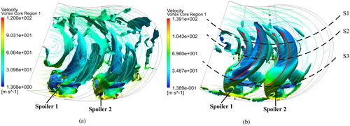
Figure 13. Turbulence eddy dissipation distribution on sections of different radius: (a) section 1; (b) section 2; (c) section 3.
In the rotating frame, there is centrifugal force on the fluid, so the mechanical energy of fluid elements per unit volume can be expressed as the following equation:
(10)
(10) where
is the velocity vector relative to the rotating frame, and
is the transport velocity vector. Taking the derivative of both sides of the equation with respect to time, the fluid power loss per unit volume can be obtained:
(11)
(11)
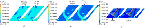
The fluid power loss per unit volume on three sections (S1, S2, S3) could be captured by the above equation. The high fluid power loss region grows larger from the outer ring to the inner ring, and the fluid power loss distribution is similar to turbulence eddy dissipation. It is proved that the vortex generated from the bionic surface spoiler affects the fluid energy dissipation, resulting in a reduction in idling drag (Figure ).
Figure 14. Power loss distribution per unit volume of fluid on sections of different radius: (a) section 1; (b) section 2; (c) section 3.
5.3. Wall shear stress analysis
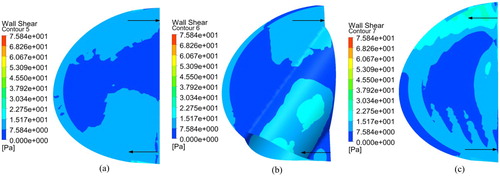
Analysis of the wall shear stress is conducted at the rotational speed of 3000 r/min. The wall shear stress is generated by the strong interaction between the fluid and the wall, and is positively related to the frictional resistance of the wall. The variation of the wall shear stress could reflect the wall friction resistance and influences the flow-field velocity.
In Figure , the wall shear stress with a bionic structure is larger than that without a bionic structure, and reaches the maximum value of 75.84 Pa. The increased wall shear stress causes higher wall friction resistance, leading to abruptly rising local velocity around the spoiler, and consequently slows down the main stream velocity. As a result, the impact on the blade becomes weaker.
Figure 15. Wall shear stress distribution on spoilers: (a) without bionic structure; (b) with bionic structure.
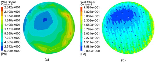
Figure shows that shear stress on the stator blade is greater than that on the rotor blade. The shear stress reaches its maximum value at the inlet of the stator. The airflow from the rotor flows out at high speed and impacts the fixed blade, resulting in large friction and shear stress in the corresponding area. The shear stress distribution on rotor blade 1 is similar to that of rotor blade 2, but the area of higher shear stress on rotor blade 2 is larger than that on rotor blade 1.
Figure 16. Wall shear stress distribution on the blade pressure surface with smooth surface spoiler: (a) rotor blade 1; (b) rotor blade 2; (c) stator blade.
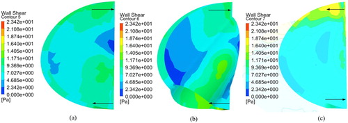
Figure 17. Wall shear stress distribution on the blade pressure surface with bionic surface spoiler: (a) rotor blade 1; (b) rotor blade 2; (c) stator blade.
The shear stress results in Figures 16 and 17 exhibit similar distributions on the blades; however, the wall shear stress with a bionic surface spoiler is higher than that with a smooth surface spoiler, which would cause decreased velocity in the main flow field and a weaker impact on the blade.
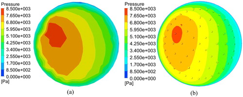
5.4. Pressure analysis
In Figure , the high-pressure area with a pit bionic structure is smaller than that without a bionic structure and the pressure is lower on the spoiler surface. The pit bionic structure can effectively reduce the local pressure, thereby affecting the blade pressure.
Figure 18. Pressure distribution on the spoiler: (a) without bionic structure; (b) with bionic structure.
Pressure on rotor blade 1 surface directly affects the rotor torque. Pressure distributions of the blade pressure surface with different surface spoilers at a rotational speed of 3000 r/min are shown in Figures and . The blade surface pressure distribution is stratified and the outer ring pressure is higher than that on the inner ring. This is because the velocity in the outer ring is higher than that in the inner ring, leading to greater impact pressure on the blade. The velocity reaches its maximum at the outlet of the rotor, then the air flows into the stator with high-speed impacts on the blade.
Figure 19. Pressure distribution of rotor blades with smooth surface spoiler: (a) rotor blade 1; (b) rotor blade 2.
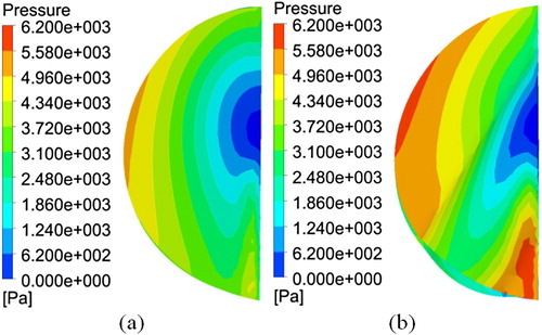
Figure 20. Pressure distribution of rotor blades with bionic surface spoiler: (a) rotor blade 1; (b) rotor blade 2.
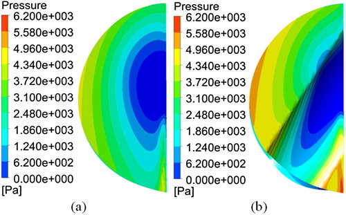
Comparing Figures and , the blade surface pressure with a bionic surface spoiler is lower than that with a smooth surface spoiler. Taking rotor blade 1 as an example, the blade torque, which is the integral of pressure along the blade surface, reaches 843.1 N with the smooth spoiler, while it is only 781.9 N with the bionic surface spoiler. This shows that the bionic surface spoiler has an influence on the impact effect on the blade surface. Owing to the impact of high-velocity airflow, the pressure on the blade is high. The lower pressure on the blade with a bionic structure proved that the velocity of the airflow striking the blade is lower, thus lowering the impact and drag on the rotor blades. Therefore, the bionic structure can greatly reduce idling power loss.
The idling torque is mainly attributed to the impact of airflow and drag on the rotor blades. From the above analysis, the bionic structure disturbs the flow, increases the fluid energy dissipation by vortex structures and wall shear stress, reduces the fluid velocity, and thus results in lower blade pressure and lower power loss.
6. Test rig
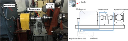
To verify the torque reduction effect of the plunger device with a bionic surface spoiler, different spoilers were fabricated and a test bench was built to conduct the idling performance experiment. To ensure the accuracy of the test, the material of the model was selected as 45 steel because of its good machinability. The plunger body structure was processed by a CNC lathe, and the bionic surface was produced by a high-accuracy machining center. The surface roughness (Ra) was 1.6. The transmission shaft was connected with the hydraulic retarder rotor. The idling torque and working chamber pressure of the rotor were measured by the torque/speed sensor and the pressure sensor, respectively, with varying rotor speeds. The test rig is shown in Figure .
Figure 21. Hydraulic retarder transmission test bench.
The maximum test speed was 3000 r/min. During the test, the traditional spoiler hydraulic retarder was filled with air, and the rotor speed was varied from 0 to 3000 r/min to test the idling power loss under different rotating conditions. The steady-state torque and working chamber pressure of the hydraulic retarder were collected at speeds of 1000, 1500, 2000, 2500 and 3000 r/min. Then, the Model B spoiler was installed in the hydraulic retarder, replacing the traditional one, and the above steady-state test was repeated. Through this steady-state test process, the torque and working chamber pressure versus rotational speed in the non-filling condition of the hydraulic retarder with regard to the two types of spoiler were obtained and are shown in Figure .
Figure 22. Test results at different rotational speeds: (a) idling torque; (b) chamber pressure; (c) difference percentage of torque and pressure.
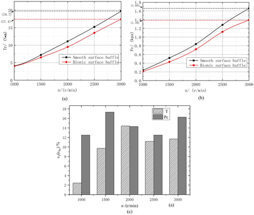
Figure (a) shows that the torque of the hydraulic retarder increases with increasing rotational speed. Besides, the torque with a bionic surface spoiler is much lower than that with a smooth surface spoiler, indicating that the bionic surface is able to reduce the power loss effectively. As shown in Figure (c), when the rotational speed increases, the ϵT increases first and reaches the maximum value at 2000 r/min. When the rotational speed is higher than 2000 r/min, the ϵT fluctuates around its maximum value and reaches 11.7% at 3000 r/min. The test results indicate that the bionic surface performed better at higher rotational speed.
The relative pressure in the working chamber at different rotational speeds is shown in Figure (b). We can see that the pressure shows a similar trend to the idling torque; the working chamber pressure increases gradually with an increasing rotational speed, and is lower with a bionic surface spoiler at the same rotational speed. There is no apparent correlation between the pressure reduction ratio and rotational speed because of airflow pressure fluctuations. The working chamber pressure decreased by 16.3% under the 3000 r/min condition.
From the above test results, we can conclude that a bionic non-smooth surface on the spoiler could reduce the working chamber pressure and the idling torque of the hydraulic retarder.
7. Conclusions
In this paper, the significance and mechanism of bionic non-smooth units for power loss reduction were analyzed. A calculation model of a hydraulic retarder with a spoiler having a bionic structure surface was established, and the effect of the bionic non-smooth surface in reducing drag on the rotor was studied. According to the internal airflow state of the hydraulic retarder, the non-smooth unit (pit and groove) size and arrangement were estimated, and the local mesh density was increased on the spoiler to capture the boundary flow behavior more effectively. Both the CFD simulations and test results show that the application of a non-smooth surface is very promising. The conclusions and outlook for future work are highlighted in the following main aspects:
Both simulations and test results prove that the spoiler with a bionic surface can effectively reduce idling power loss; moreover, with the increase in rotational speed, the drag reduction ratio gradually increases. Compared to the spoiler without a bionic structure, the torque could be reduced by up to 11.7% at the maximum rotational speed of 3000 r/min in the test results.
From analysis of the flow-field characteristics, the bionic structure disturbs the flow and causes secondary flows, which enhance the fluid energy dissipation and wall shear stress on the blade and reduce the airflow velocity and blade pressure. This explains the internal flow mechanism for drag reduction and idling loss inhibition. Through analysis and discussion at the level of the vortex structure, the properties could be improved effectively by changing the flow-field structure.
This study indicates that the bionic non-smooth structure is able to suppress power losses in the hydraulic retarder. However, the bionic structures investigated in this paper were limited and a diversity of bionic structures remains to be studied. Furthermore, the structural dimensions are presumed to affect the performance; therefore, the structure remains to be optimized. In addition, the application of bionic surfaces on major structures of the hydraulic retarder other than the spoiler may be another significant research direction to improve the braking performance.
Disclosure statement
No potential conflict of interest was reported by the author(s).
Additional information
Funding
References
- Akbarian, E., Najafi, B., Jafari, M., Ardabili, S., Shamshirband, S., & Chau, K.-W. (2018). Experimental and computational fluid dynamics-based numerical simulation of using natural gas in a dual-fueled diesel engine. Engineering Applications of Computational Fluid Mechanics, 12(1), 517–534. doi: 10.1080/19942060.2018.1472670
- An, Q., Zhang, B., Liu, G., Yang, W., Zhao, H., Wang, J., & Wang, L. (2019). Directional droplet-actuation and fluid-resistance reduction performance on the bio-inspired shark-fin-like superhydrophobic surface. Journal of the Taiwan Institute of Chemical Engineers, 97, 389–396. doi: 10.1016/j.jtice.2019.01.015
- Bajsanski, I., Stojakovic, V., Tepavcevic, B., Jovanovic, M., & Mitov, D. (2017). An application of the shark skin denticle geometry for windbreak fence design and fabrication. Journal of Bionic Engineering, 14(3), 579–587. doi: 10.1016/S1672-6529(16)60423-7
- Carpenter, P. (1989). Status of transition delay using compliant walls. In D. M. Bushnell & J. N. Hefner (Eds.), Viscous drag reduction in boundary layers. Progress in astronautics and aeronautics (pp. 79–113). Washington, DC: AIAA.
- Chen, W., Min, X., Gao, D., Guo, A., & Li, H. (2018). Experimental investigation of aerodynamic forces and flow structures of bionic cylinders based on harbor seal vibrissa. Experimental Thermal and Fluid Science, 99, 169–180. doi: 10.1016/j.expthermflusci.2018.07.033
- Chen, X., Zeng, L., & Chen, X. (2019). Eccentric correction of piston based on bionic micro-texture technology for the gap seal hydraulic cylinder. Micro & Nano Letters, 14(1), 33–37. doi: 10.1049/mnl.2018.5102
- Cong, Q., Ren, L., Wu, L., Chen, B., Li, A., & Hu, A. (1992). Taxonomic research on geometric non smooth animal surface shapes. Transactions of the Chinese Society of Agricultural Engineering, 8(2), 7–12.
- Dinkelacker, A, Nitschke-Kowsky, P., & Reif, W.-E. (1987). On the possibility of drag reduction with the help of longitudinal ridges in the walls. In H. W. Liepmann & R. Narasimha (Eds.), Proceedings of the IUTAM symposium on turbulence management and relaminarization (pp. 109–120). Bangalore, India: Springer, Berlin.
- Fluent Inc. (2003). Introductory FLUENT notes for fluent v6.1.
- Ghalandari, M., Koohshahi, E., Mohamadian, F., Shamshirband, S., & Chau, K. (2019). Numerical simulation of nanofluid flow inside a root canal. Engineering Applications of Computational Fluid Mechanics, 13(1), 254–264. doi: 10.1080/19942060.2019.1578696
- Gray, J. (1936). Studies in animal locomotion VI: The propulsive powers of the dolphin. Journal of Experimental Biology, 13, 192–199.
- Gu, Y., Zhao, G., Zheng, J., Li, Z., Liu, W., & Muhammad, F. (2014). Experimental and numerical investigation on drag reduction of non-smooth bionic jet surface. Ocean Engineering, 81, 50–57. doi: 10.1016/j.oceaneng.2014.02.015
- Guo, X., & Yan, Q. (2003). CN Patent No. 2554057. Beijing: National Intellectual Property Administration, PRC.
- Hu, H., Song, B., & Liu, Z. (2011). Research at the computational methods of flow fields over riblets surface. Acta Aerodynamica Sinica, 29(3), 348–354.
- Jiangsu university. (2008). CN Patent No. 200810020498.2. Beijing: National Intellectual Property Administration, PRC.
- Jin, Z., Li, G., Wang, J., & Zhang, Z. (2019). Design, modeling, and experiments of the vortex-induced vibration piezoelectric energy harvester with bionic attachments. Complexity, 2019, 1–13.
- Li, S. (2016). Research on flow status under low oil charging ratio operating condition and idling power loss mechanism in a hydraulic retarder (Master’s Thesis). Beijing Institute of Technology, Beijing.
- Li, W. (2009). Numerical simulation of bionic wing for drag reduction (Master’s Thesis). Retrieved from http://www.cnki.net
- Li, X., Yu, X., Cheng, X., & Miao, L. (2012). Large eddy simulation on internal flow field of hydraulic retarder and characteristics prediction. Journal of Jiangsu University, 33(4), 385–389, 419.
- Li, Z., & Tian, T. (2010). Numerical study of flow and heat transfer in dimpled channel with simple fish-scale cavity. Journal of Thermal Science and Technology, 9(1), 23–30.
- Liu, C. (2015). Research on reducing resistance and increasing efficiency of hydraulic torque converter with multiple biological characteristics (Master’s Thesis). Retrieved from http://www.cnki.net
- Liu, M. (2012). Study on the resistance performance of bionic body (Master’s Thesis). Retrieved from http://www.cnki.net
- Liu, Z., & Dong, W. (2006). The effects of the tip shape of V-groove on drag reduction and flow field characteristics by numerical analysis. Chinese Journal of Hydraulics, 21(2), 223–231.
- Liu, E., Li, L., Wang, G., Zeng, Z., Zhao, W., & Xue, Q. (2017). Drag reduction through self-texturing compliant bionic materials. Scientific Reports, 7, ID:40038. doi: 10.1038/srep40038
- Liu, M., Li, S., Wu, Z., Zhang, K., Wang, S., & Liang, X. (2019). Entropy generation analysis for grooved structure plate flow. European Journal of Mechanics/B Fluids, 77, 87–97. doi: 10.1016/j.euromechflu.2019.04.017
- Liu, C., Zhu, L., Li, J., & Liang, Y. (2019). Fabrication of superhydrophobic bionic surface integrating with VOF simulation studies of liquid drop impacting. Microscopy Research and Technique, 82(5), 615–623. doi: 10.1002/jemt.23208
- Mezghani, S., Demirci, I., Zahouani, H., & Mansori, M. (2012). The effect of groove texture patterns on piston-ring pack friction. Precision Engineering, 36, 210–217. doi: 10.1016/j.precisioneng.2011.09.008
- Mosavi, A., Shamshirband, S., Salwana, E., Chau, K.-W., & Tah, J. (2019). Prediction of multi-inputs bubble column reactor using a novel hybrid model of computational fluid dynamics and machine learning. Engineering Applications of Computational Fluid Mechanics, 13(1), 482–492. doi: 10.1080/19942060.2019.1613448
- Mou, B., He, B.-J., Zhao, D.-X., & Chau, K.-W. (2017). Numerical simulation of the effects of building dimensional variation on wind pressure distribution. Engineering Applications of Computational Fluid Mechanics, 11(1), 293–309. doi: 10.1080/19942060.2017.1281845
- Pan, G., & Huang, Q. (2010). Numerical simulation research about the drag reduction over riblet structure with different space of gyroidal object. Acta Aerodynamica Sinica, 28(3), 267–271,290.
- Parker, R. (2004). Efficient eigensolution, dynamic response, and eigensensitivity of serpentine belt drives. Journal of Sound and Vibration, 270(1), 15–38. doi: 10.1016/S0022-460X(03)00259-1
- Ramezanizadeh, M., Nazari, M., Ahmadi, M., & Chau, K.-W. (2019). Experimental and numerical analysis of a nanofluidic thermosyphon heat exchanger. Engineering Applications of Computational Fluid Mechanics, 13(1), 40–47. doi: 10.1080/19942060.2018.1518272
- Ren, L., & Cong, X. (1992). The interface adhesion of the basic characteristics of the non-smooth surface. Transactions of the Chinese Society of Agricultural Engineering, 8(1), 16–22.
- Ren, L., Peng, Z., Chen, Q., Zhao, G., & Wang, T. (2007). Experimental study on efficiency enhancement of centrifugal water pump by bionic non-smooth technique. Journal of Jilin University (Engineering and Technology Edition), 37(3), 575–581.
- Schlichting, H. (1991). Boundary layer theory. Beijing: The Science Publishing Co.
- Song, X., Lin, P., Liu, R., & Zhou, P. (2017). Skin friction reduction characteristics of variable ovoid non-smooth surfaces. Journal of Zhejiang University-Science A (Applied Physics & Engineering), 18(1), 59–66. doi: 10.1631/jzus.A1500324
- Tian, L. (2005). Bionic study of drag reduction between air and non-smooth surface of blunt body of revolution model (Doctoral Thesis). Retrieved from http://www.cnki.net
- Tian, L., Ren, L., & Liu, Q. (2007). The mechanism of drag reduction around bodies of revolution using bionic non-smooth surfaces. Journal of Bionic Engineering, 4(2), 109–116. doi: 10.1016/S1672-6529(07)60022-5
- Wang, K., Wang, W., Fu, F., & Xiao, D. (2014). CN Patent No.102748410B. Beijing: National Intellectual Property Administration, PRC.
- Wei, G. (2011). CN Patent No. 200910174842.8. Beijing: National Intellectual Property Administration, PRC.
- Wei, W., Li, H., Zou, B., & Yan, Q. (2010). Study on braking performance and analysis of two-phase flow in vehicular hydraulic retarder. Transactions of Beijing Institute of Technology, 30(11), 1281–1284, 1320.
- Wei, W., Mu, H., & Yan, Q. (2015). Suppression effect analysis of spoiler on idling loss of vehicular hydraulic retarder. Journal of Harbin Institute of Technology, 47(7), 73–77.
- Wu, C., & Xu, M. (2012). Air losing experimental study of heavy vehicle hydraulic retarder. Vehicle & Power Technology, 2012(1), 23–25.
- Wu, L., Jiao, Z., Song, Y., Liu, C., Wang, H., & Yan, Y. (2018). Experimental investigations on drag-reduction characteristics of bionic surface with water-trapping microstructures of fish scales. Scientific Reports, 8, ID:12186. doi: 10.1038/s41598-018-30490-x
- Yan, Q., Zou, B., & Wei, W. (2011). Numerical investigation of hydraulic tractor-retarder assembly under traction work condition. Journal of Beijing Institute of Technology, 20(4), 472–477.
- Yang, X., & Ren, L. (2003). Types and mechanisms of shape drag reduction. Transactions of the Chinese Society of Agricultural Machinery, 31(1), 130–133.
- Zeng, M., Zhou, Y., & Ma, Y. (2018). Evaluation of sealing performance of bearing rings of roller-cone bits based on grid-shaped bionic non-smooth surface. Advances in Mechanical Engineering, 10(5), 1–21. doi: 10.1177/1687814018774187
- Zhang, C. (2007). Drag reduction of bodies of revolution by flow control using bionic non-smooth surface (Doctoral Thesis). Retrieved from http://www.cnki.net
- Zhang, S., & Hu, W. (2015). The numerical study of bionic wavy leading-edge wing in dynamic stall control. Chinese Journal of Hydraulics, 30(1), 24–32.
- Zhou, H., Zhai, H., Ding, Y., & Wang, G. (2017). Numerical investigation of passive control flow to improve tire hydroplaning performance using a V-riblet non-smooth surface. Advances in Mechanical Engineering, 9(11), 1–13.