
 ?Mathematical formulae have been encoded as MathML and are displayed in this HTML version using MathJax in order to improve their display. Uncheck the box to turn MathJax off. This feature requires Javascript. Click on a formula to zoom.
ABSTRACT
In the European research project ‘Surfacing System for Ship Recovery’ (SuSy), gas inflated balloons are envisaged to be used for providing reserve buoyancy to damaged ships for the purpose of preventing ship capsizing and/or sinking, along with lifting wreckages from the seabed. This paper presents the proof of concept tests of the prototype salvage units applied on a full-scale demonstrator section of a double bottom structure, together with measurements of its structural response. Two scenarios of internal and external deployment of the inflatable rescue units were examined. In both cases, the demonstrator was successfully salvaged. Data from the structural response of the demonstrator revealed certain operational aspects of the salvage system which directly affected the response of the salvaged structure. The monitored structural response of the demonstrator during operation of the salvage system was well within the elastic regime of its material (Grade A steel). Accordingly, finite element simulation of the salvage system supporting structure was conducted. The results of these simulations were found to be well correlated to the corresponding experimental measurements.
1. Introduction
A large number of ship accidents continue to occur despite the improvements of the regulatory framework. These accidents result in the loss of cargos, pollution of the environment, and above all, loss of human life. Especially for tankers, an accident hinders at the possibility of an oil spill corresponding to great environmental and financial consequences (Grey Citation1999; Wilkins Citation2004; Burgherr Citation2007; Yamada Citation2009; Kimrey and Cocanour Citation2011; Chiu et al. Citation2017).
According to oil spill statistics for 2015, a report issued by the International Tanker Owners Pollution Federation Ltd (ITOPF), the majority of oil spill incidents concerning tankers (>95%) results from routine operations such as loading, discharging and bunkering and lead to small (<7 tonnes) to medium (<700 tonnes) spills (ITOPF Citation2016). Accidental causes such as collisions and groundings generally give rise to much larger spills that involve quantities more than 700 tonnes. Such events can seriously undermine the structural integrity of a vessel and furthermore may reduce both her stability and floatability (Dhanak and Xiros Citation2016; Youssef et al. Citation2016; Ćorak et al. Citation2017).
Post-accidental rectification actions, such as bringing the ship to its upright position, may minimise the potential oil spill and secure that the residual damaged hull strength is not further compromised (Zhao Citation1989; Paik et al. Citation1998; Navy US Citation2000; Kim et al. Citation2013; Pan et al. Citation2014; Zhang et al. Citation2016). However, such actions are dictated mostly by time and a great deal of uncertainty, which both are critical factors after an accident occurs (Gerigk Citation2012; Mayer Citation2017). All salvage actions must be as swift as possible since a damaged ship's condition in open waters is always expected to deteriorate due to various factors, such as weather conditions, sea state and also due to the uncertainty of the structural integrity of the vessel (Bartholomew et al. Citation1992; Fang and Das Citation2005; Navy US Citation2013). To this end, many researchers have focused on determining the ultimate strength of a damaged hull after accidents and especially after collision or grounding events (Gordo and Guedes Soares Citation1996; Paik et al. Citation1998; Wang et al. Citation2002; Fang and Das Citation2005; Luís et al. Citation2009; Nguyen et al. Citation2011; Paik et al. Citation2012; Pollalis and Samuelides Citation2013). Maritime companies in collaboration with classification societies have also established emergency response protocols to safely and efficiently deal with such crises, see e.g. American Bureau of Shipping (Citation2010). Moreover, the emphasis has been given to the development of salvage engineering software to facilitate the support salvors course of action (Jensen Citation1999; Anastasia Citation2014).
In this work, an innovative salvage concept is presented, studied within the framework of the research project SuSy. The scope of SuSy project (Surface System for ship recovery, www.su-sy.eu) was to further develop and adapt a well-known submarine rescue technology into systems capable of being used in merchant ships and fish vessels, in an emergency situation.
This system relies on inflatable devices which, in case of an accident or an emergency situation, will either be pre-fitted inside the ship and inflated or they would be post-fitted on the hull of the ship by salvage or emergency response teams with special attachment arrangements and deployed in order to give reserve buoyancy to the ship. This system could enable the crew and the salvage teams to readily and promptly aid a ship in case of an accident or emergency. Moreover, this could be achieved with a reduced cost, considering the high costs associated with salvage operations (Alexander Citation2012).
The activation of such a salvage system on an actual vessel would most definitely have a considerable impact on its global load distribution and therefore the load-bearing capacity of the structure has to be assessed. To this end, an investigation of the global response of a structurally compromised Aframax tanker with the use of such salvage approach was presented in the work of Zilakos et al. (Citation2011). In this study, a three-compartment finite element model of the vessel was employed and its response was assessed under the combined loading according to IACS common structural rules (IACS Citation2010) and the buoyant forces excited by the proposed salvage system. As a continuation of this work, the scope of the present paper is to determine the local structural response of a naval structure under the loads exerted by the proposed salvage system. The rescue units were placed either internally or externally on the demonstrator naval structure, which in turn was submerged and brought on the surface solely by the lifting forces generated by the rescue units. The scope of the tests was to examine the feasibility and the operational parameters of the developed salvage technology, as well as to monitor the local structural response of the demonstrator.
This paper is organised as follows. Firstly, the SuSy salvage concept is described, followed by a brief description of the fabrication material and geometry of the inflatable rescue units. In Section 3, the preparation of the proof concept test is presented by briefly describing the demonstrator structure and the test site. An overview of the gas generation systems used and the set-up of involved instrumentation are also provided. In Section 4, the testing protocol is described and the corresponding measured magnitudes are presented. Finally, in Section 5, finite element simulations’ results of certain components of the salvage units under the excited buoyancy forces are correlated with actual sensor measurements recorded during the proof of concept tests.
2. The SuSy system: a prototype salvage system
2.1. The SuSy concept
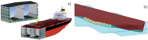
The SuSy system aims to provide reserve buoyancy to damaged or capsized vessels and to potentially lift sunken ships from the seabed. It basically consists of inflatable balloon-like devices which can be externally or internally attached to a vessel.
When used externally, they can be attached to the outer hull of the vessel, in structurally strong points (e.g. bulkheads), giving reserve buoyancy when inflated. The salvage units will be either directly attached to the wrecked hull or attached on a lifting net or platform. The whole task can be undertaken by diver teams while for deeper locations ROVs could also be involved. The activation of the salvage system is remotely controlled through the use of air triggering valve system that could be located on the salvage ship.
In the case of internal use, when inflated they can force most of the accumulated water to outflow from the damaged compartment and provide additional buoyancy to the vessel (). Although the method of induced buoyancy for dewatering vessel's compartments and providing buoyancy is not an utterly new idea in salvors’ common practice, such concepts are usually purpose-built, improvised systems (Bryant Citation1970; Winner and Searle Citation1970; Wade Citation1975; Carithers and Tibbert Citation1981; Alexander et al. Citation1986; Ventikos et al. Citation2014; Dhanak and Xiros Citation2016).
Figure 1. Conceptual depiction of (a) internal application of SuSy devices inflated inside the double hull of an oil-tanker vessel and (b) external application of the SuSy salvage system inflated at the starboard side of the vessel.
The cost-effectiveness of the SuSy system was assessed through the development of a life-cycle cost model (Fischer Citation2013). The results of the analyses indicated that the use of the system for salvage purposes (i.e. externally deployed system) is more likely to break-even after its second application. On the other hand, this is not the case for the onboard preinstalled system (i.e. internally deployed system), where the results were not conclusive. The main reason lays in the low frequency and the random nature of the accidents which did not allow for a de facto break-even during the whole life expectancy of the ship. However, in case of an accident that involves possible loss of cargo or extended damage on the vessel, the implementation cost of such system outweighs significantly the cost of the resulting consequences.
2.2. Description of the inflatable rescue units
The inflatable devices of the SuSy project were fabricated from the rubber-coated fabric composite system. The compounds of this composite system were selected in a way to bring specific chemical, physical and mechanical properties to the buoyancy carriers, such as airtightness, resistance against sea water and fuel oil, good performance against puncture and abrasion, etc. Moreover, all the above material requirements should be met by a medium to low cost composite system that could enable the practical implementation of the concept in a large vessel at a realistic cost. An analysis carried out within the framework of SuSy project led to the following composite system: a polychloroprene (CR) coating and an orthotropic fabric comprised of PA-aramid fibres.
Two geometries were selected for the design of the inflatables, a spherocylindrical and a spherical one. The selection of geometry depends on whether the devices would be internally or externally deployed. For the case of the internal devices deployment, the spherocylindrical shape was considered as the most suitable choice, since it consists of two simple smooth geometries (no sharp edges) that could be easily bonded together. In addition, such design when deployed uses the most of a compartment space, thus maximising both the discharge of accumulated water and the provided buoyancy. For the case of the external devices deployment, a spherical geometry was selected since such simple, symmetrical geometry exhibits the lowest surface to volume ratio, thus maximising the generated buoyancy force while using the least possible material.
Both types of inflatable devices are equipped with pressure relief valves, which are triggered when the differential pressure reaches the threshold value of 0.6 bar (= 0.06 MPa). This leads to a constant operational internal pressure for the inflatable units of 0.6 bar, independently of the depth they operate. Therefore, they are allowed to be deployed in great depths, without being subjected to significant volume changes or having to withstand high values of external hydrostatic pressure.
3. Preparation of open water proof of concept tests
3.1. Description of the demonstrator
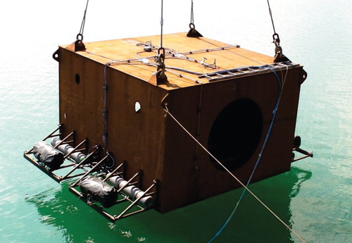
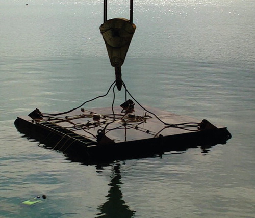
For the proof of concept tests a 3.6 m long, full-scale section of an 113,000 tn DWT Aframax tanker's double bottom was selected to be constructed and used as a demonstrator for the developed salvage technologies (). The goal was to study and validate the operational parameters of the ‘SuSy’ concept in an actual vessel's compartment. Circular cut-outs of 1.6 m were opened at both side plates of the demonstrator, both for access purposes and for allowing the water to be blown out when the spherocylindrical inflatable devices were activated. The steel used for the construction of the double bottom was Grade A steel with minimum yield stress , Young's Modulus
and Poisson's ratio v = 0.3, conforming to CitationASTM A131.
Figure 2. External rescue devices attached on the demonstrator (gas tanks, inflatables in their protective cases and the support frames are shown).
3.2. Description of the test site
The test site was situated within the premises of Chalkis Shipyards (38°25′26.6″N 23°35′58.0″E) located in Vathi Avlidas on the Greek mainland, close to the town of Chalkis. The tests were carried out just besides the shipyard berth, allowing the use of the large lifting capacity dock cranes.
The shipyard is located in a semi-enclosed bay, protected from high seas by the surrounding topography (mainland coast, enclosure and the adjacent island of Evia). The water depth next to the shipyard berth was approximately 8 m, allowing the submergence of the demonstrator to an adequate depth without reaching the seabed that could cause entanglement, uneven rest position or suction effects from a soft substrate. Unfortunately, water clarity within the shipyard precincts was less than 1 m during the tests due to strong winds and the activities in the shipyard. Water currents in the area were negligible. Although the weather was variable (sun, clouds and rain), the onset of autumn air temperatures reached 20oC during the tests with sea temperatures remaining stable at approximately 18oC.
3.3. Preparation of the gas generation systems
The inflation of the SuSy devices for the internal deployment scenario was conducted using a low-pressure air system. The reasoning lies behind the fact that for this particular scenario the salvage system is envisaged to be pre-fitted inside the double bottom and double side compartments of the vessel () and accordingly take advantage of the existing low-pressure distribution network of the ship. To this end, a high capacity low-pressure tank was employed in order to store compressed air at 30 bar and subsequently delivered it to the two inflatable devices inside the double bottom structure through flexible pressure hoses.
For the case of the external devices deployment scenario, special mixtures of various gases can, in general, be used to inflate the balloons (Bryant Citation1970). Within the framework of SuSy project, several types of gas production systems have been investigated. Among the prevailing candidates are pressurised systems (e.g. Nitrogen, Carbon Dioxide), catalytic decomposition systems (monopropellant system, e.g. Hydrazine, Nitrous Oxide) and finally solid-fuelled (e.g. Ammonium Perchlorate, Ammonium Nitrate) and liquid-fuelled systems (bipropellant system, e.g. Nitric Acid + Ammonia, Nitrous Oxide + Butane), a well-known technology used in rocket propulsion applications. Apart from the pressurised systems the rest of the gas production systems result to a small specific volume configuration and can inflate the balloons in very short time, compensating large external hydrostatic pressures, corresponding to large sea depths. Solid fuel or liquid fuel systems might be well suited for wreckage removal off the seabed at large sea depths, where high internal balloon pressures are required in order to compensate for the large hydrostatic pressure. On the other hand, such systems are not well suited for use on-board a tanker due to their flammable and explosive nature (Bryant Citation1970), leaving the pressurised systems as a safer and more suitable option.
For the present open water tests, a cold gas generator was involved, consisting of a 50 l pressure tank filled with nitrogen, stored at approx. 100 bar. The pressure tank, along with its remotely operated trigger system, was installed on a frame structure. The spherical inflatable device was also mounted on the same frame, initially stored in a protective case. Subsequently, the whole assembly unit was attached on the double bottom demonstrator. In total four such units were installed on the demonstrator, two at each side ().
3.4. Sensors arrangement
The structural response of the double bottom demonstrator and of the supporting frames under the loads excited by the inflation of the SuSy devices has been monitored with the aid of 0/45/90 triple strain gauge rosettes. Four sensors were used to monitor the response of the top and bottom plates (A3, A4, C1 and C2) and four for the response of the T-profile stiffeners of the top plate (A1, A2, B1 and B2), as shown in . The latter were placed on the location where the two internal SuSy inflatables were attached to the structure, allowing for the measurement of the stiffeners’ response under the loads exerted by the two inflatables during the internal devices deployment scenario. The strain gauges installed on the top and bottom plates, and on the stiffeners’ flanges have the same alignment, as shown in . Those installed on the stiffeners’ webs have their 0o measuring direction aligned with the direction of the stiffener.
Figure 3. Middle section (a) and top view (b) of the double bottom demonstrator depicting the strain gauges’ positions (P and S denote port and starboard side respectively, dimensions in mm).
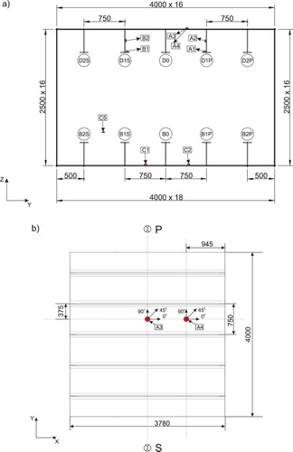
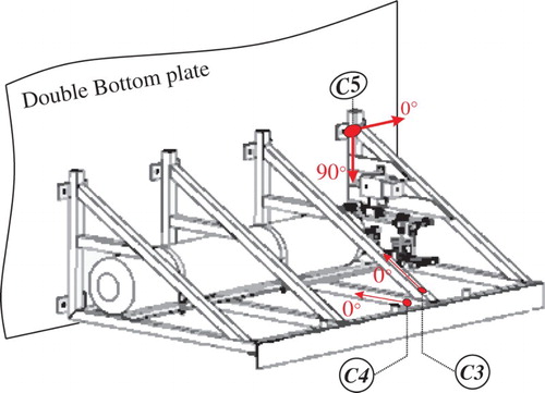
For the open water test of the external devices deployment, three additional strain gauges were installed (C3, C4 and C5, ). Two single gauge sensors (C3 and C4) were installed on the supporting frame to measure its response under the buoyancy force generated by the spherical inflatable, whereas one double gauge sensor (C5) was installed on the inner side of the double bottom plating at one of the frame's attachment points to assess the structure's response at the attachment points under the excited lifting forces (). The water sealing of all strain gauges was achieved with the use of polyurethane paste.
Figure 4. Sketch of the external frame depicting the strain gauges’ positions and measuring directions.
4. Open water proof of concept tests
4.1. Testing protocol
The testing protocol was comprised of the following steps:
The demonstrator was lifted and subsequently deployed into the water, using a dock crane. The submersion depth of the demonstrator's top plate was approximately 1 m.
The demonstrator remained completely submerged for approximately 15 min to ensure that the temperature of the steel dropped close enough to that of the sea water to avoid any spurious strain measurements.
The gas distribution system was activated. For the case of the internal devices deployment, the compressed air tank (located in land) delivered air to the two inflatable devices, which were then deployed inside the double bottom. In the external devices deployment case, the high-pressure gas system was remotely activated using air triggered valves, deploying the externally attached spherical inflatables.
4.2. Internal devices deployment: test results and strain measurements
After activating the pressure system, the double bottom demonstrator gradually and stably emerged to the surface and finally remained afloat on an even keel. The whole process lasted about 4.5 min and at the end of this period, the structure remained afloat with a freeboard of approximately 30 cm. The two SuSy devices managed to blow the water out of the compartment and provide the required buoyancy for lifting the double bottom structure afloat.
presents the response of the webs of the top plate stiffeners in terms of stresses versus time, calculated from the corresponding monitored strains (sensor B1 malfunctioned).
Figure 5. Stresses on the webs of the top plate stiffeners.
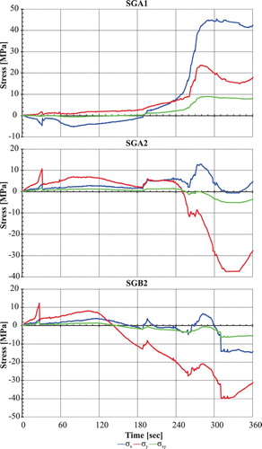
Approximately 120 s after the activation of the system, there was a clear visual indication that the structure began to emerge since a significant part of the lifting wires’ ferrules had emerged. The beginning of emersion process was also reflected in the strain gauges’ recordings. At approx. 120 s, a gradual rise of the absolute value of the stresses at locations A1, A2 and B2 (all at the top plate stiffeners) can be observed in .
At 188 s after the activation of the system, one of the two inflatables (the starboard one, that closer to the dockside) had already been deployed. This became evident as air bubbles started coming out continuously from the starboard side, of the demonstrator, which indicated that the differential pressure relief valve on this inflatable was triggered. Therefore, the pressure inside the inflatable had reached its maximum value and the excess air was released. In addition, the starboard side lifting wires started slightly to loosen, which can explain why the absolute value of stress σy at location B2 (at the web of the starboard T-stiffener) continued to increase ().
At 260 s after the activation of the system, the demonstrator's top plate reached the water surface. However, a slight inclination was observed in favour of the port side. This slight tilt of the demonstrator towards the port side during the emersion face also explains the rise of the absolute value of stress σy at location A2 (at the web of the port T-stiffener) until the demonstrator reached an even equilibrium position at around 283 s. From this point forward the structure continued to emerge in an even keel, thus absolute values of stress σy at both locations A2 and B2 retained an increasing trend ().
At around 312 s after the activation of the system, the structure reached its maximum emersion freeboard (∼30 cm). It can be observed in that the lifting wires are completely loose and partially resting on the demonstrator's top plate. Since the structure remained in an equilibrium position, the strain recordings remained almost constant. However, at approx. 330 s and forward, a decrease on the absolute values of stresses can be observed, especially for the case of stress σy at locations A2 and B2 (). At this point, the pressure delivery system was cut off and hence a slight decrease of the internal pressure (and subsequently of the volume) of the inflatables occurred. That led to a decrease of the stresses response, in particular of those at the top plate stiffeners, due to weaker contact between the inflatables and those stiffeners.
Figure 6. After 312 s, the demonstrator remained afloat at its maximum freeboard (approx. 30 cm).
The peak and mean stress values, as calculated from the recorded strains, are depicted in for all sensors. In general, the calculated stresses were found to be relatively low after the start of the emersion phase (i.e. after approx. 120 s). All recorded peak stress values were found less than 54 MPa which is the overall maximum stress peak value at location A1 in the x-direction. Especially for the two stiffeners, which served as the main load-bearing structural members for the buoyancy forces excited by the inflatable devices, the exhibited absolute peak stresses along the vertical direction (σy) never exceeded 45 MPa. (). It can also be seen that the calculated equivalent stresses at the measuring points of the demonstrator were well within the elastic range of grade A steel (
).
Table 1. Peak and mean stress values with their 95% confidence intervals for each measuring location for the emersion phase and forward (time > 120 s) along 0° (σx), 90° (σy), 45° (σxy) sensor's directions and the calculated equivalent von Mises stress, σν (units: MPa).
4.3. External devices deployment: test results and strain measurements
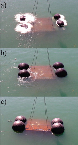
For the case of external devices deployment, the duration of the inflatables’ deployment and demonstrator's emersion phase was considerably smaller compared to that of the internal devices deployment case (in total < 2 min). The use of high-pressure gas led to a much quicker inflation of the SuSy devices. Three distinct phases were identified during the external devices deployment scenario: (i) the emersion of the spherical inflatables ((a)), (ii) their full deployment ((b)) and finally (iii) the emersion of the structure ((c)).
Figure 7. (a) Emersion of the partially inflated spherical inflatables at approx. 7 s (phase i); (b) beginning of the demonstrator's emersion at approx. 50 s (phase ii); (c) end of the demonstrator's emersion at approx. 120 s (phase iii).
Unfortunately, during this second part of the open water tests, sensor C1 also failed to record strains in any measuring direction. Similarly to the internal devices deployment case, the stresses along the sensors’ measuring directions and the equivalent stress were calculated based on the strain gauges recordings ().
Figure 8. Stresses at the frame (sensors C3, C4) and at its attachment to the demonstrator (sensor C5).
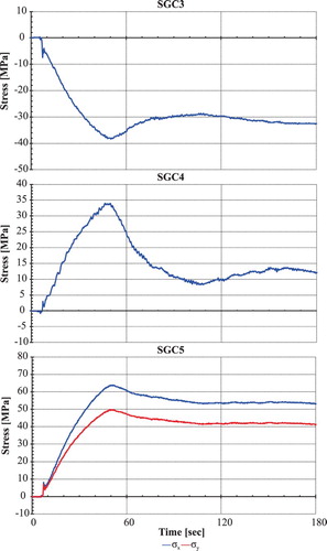
Approximately 7 s after the activation of the system, the SuSy inflatables (yet partially inflated) poked out of the water surface (phase i, (a)), an event that is also reflected on the stress curves in . A small spike on stresses can be observed for sensors C3, C4 and C5 in at around 7 s. Stresses continued to increase until approx. 50 s after the inflation, when peak stress values are observed (phase ii, (b) and ). At that time, the inflatables were fully deployed and the structure began to emerge, which subsequently led the lifting wires to loosen ((b)). After the end of the structure emersion phase (end of phase iii, (c)), the demonstrator remained afloat at an equilibrium position due to the buoyancy generated by the four inflatable units, leading to almost constant stresses (see for time>120 s). In (c), it can be observed that the lifting wires were loose, leaving the hoist rings resting on the demonstrator top plate.
The stresses developed in this case are shown in and were significantly lower compared to those of the internal devices deployment case, except for the stresses developed at the vicinity of the attachment point of the frame. In particular, maximum absolute stresses at all measuring locations on the demonstrator (A1, A2, A3 A4, B1, B2 C1 and C2) were found less than 4 MPa. Regarding stresses on the frame of the rescue units, peak values occurred at location C5 and were and
. Peak stress values were developed at the beginning of the emersion phase (Time ≈ 50 s) and for the other two frame measuring points were equal to
and
. Similarly to the case of the internal devices inflation, all calculated equivalent stress were found to be well below the yield stress of Grade A steel (
).
Table 2. Peak and mean stress values with their 95% confidence intervals for each measuring location for 0 s <time<120 s, along 0° (σx), 90° (σy), 45° (σxy) sensor's directions and the calculated equivalent von Mises stress, σν (units: MPa).
5. Finite element analysis of the external frame module
Non-linear finite element analysis was carried out in ANSYS to study the response of the external devices supporting frame (see ) under the buoyancy loads excited by the spherical inflatables. A finite element model of one frame module was created using solid elements (SOLID 185) and was constrained at the attachment points. Steel was modelled as a bilinear elastic plastic material with a modulus of elasticity of 205 GPa and yield stress equal to 235 MPa. The hardening was taken equal to 0.02 times the Young's modulus. Since the load history of the buoyancy force generated by the spherical inflatables was not known, a constant vertical force (Fz) was applied on the frame, at the attachment point of the inflatable, to model buoyancy load. The magnitude of this vertical force was calculated for two cases: (1) for the demonstrator in an equilibrium position after the end of the test, as depicted in (c), where Fz ≈ 20,738 N and (2) for the case where maximum buoyancy force is generated, i.e. when the spherical inflatable is fully deployed and fully submerged, where Fz ≈ 36,112 N (see Appendix). The first case can actually be validated by the test measurements. The measured strains and accordingly the calculated stresses for locations C3 and C4 were correlated with the finite element analysis results. For this comparison, the mean stress values and the 95% confidence intervals for locations C3 and C4 were calculated for (). During the examined time interval, the demonstrator was found in an equilibrium position, remaining afloat due to buoyancy forces generated by the four spherical inflatables ((c)). In , the measured test values are juxtaposed against the stress values extracted from the finite element model at locations C3 and C4.
Figure 9. Response of the frame under maximum buoyancy load in terms of von Mises stress (in MPa).
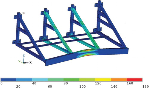
Table 3. Mean stress values with their 95% confidence intervals at locations C3 and C4 for 120 s ≤ time ≤ 180 s.
It can be observed that the results of the finite element analysis are in good agreement with the test results. Therefore, the followed modelling approach could also be used to assess the response of the frame modules under the maximum generated buoyancy force. Since the submersion depth of the double bottom structure during the open water test did not allow for the full deployment of the inflatables underwater, the wetted area of the buoyant media was less than being fully immersed and subsequently less buoyant force was generated. Hence, there are no test data available for the validation of the finite element analysis of the second case. The computed stress values for the second analysis case at locations C3 and C4 were equal to −65.4 and 55.2.0 MPa, respectively, which were (as expected) above the corresponding measured peak stress values of – 38.41 and 34.0 MPa.
In , the von Mises stresses developed on the frame are depicted for the case of maximum buoyancy loading, from where it is evident that the frame's response is well within the elastic region of the steel material ().
6. Conclusions
Two deployment scenarios for the prototype salvage units were tested during open water tests, i.e. internal and external devices deployment. The former system is envisaged to be pre-fitted inside the double bottom and double side compartments of a vessel, while the latter to be attached to strong points of the outer hull by salvors team. The two salvage systems also differ in the shape of the employed inflatable rescue units, the inflation gas system and in the deployment time. Therefore, different patterns and levels of stresses were observed during the tests. The structural monitoring system used in the field tests was comprised of a network of strain gauges. The sensors were installed on both the test bed structure and the supporting frames of the salvage system to assess their response. The analysis of the sensors’ recordings indicates that in general, for the case of internal devices deployment, higher stresses were developed on the structure compared to the external devices deployment scenario. This is attributed to the considerable interaction between the capsule-shape inflatables and the various structural members of the demonstrator. The occurrence of strong interactions has been also verified by FE simulations of the internal deployment scenario, which suggests that significant contact interactions between the balloons and the surrounding metallic structure occur, during the salvage operation (Zilakos and Toulios Citation2018). On the other hand, the recordings of the external devices deployment case suggest that the induced buoyancy forces had a more local effect on the structure. In general, the measured strains for both scenarios were found to be well within the elastic region of the common marine grade steel (). The results of the finite element analysis of the supporting frame structure for the external salvage system were well correlated with the experimental measurements. Hence, the followed modelling approach can be used to assess and optimise the frame structure to achieve a strong, lightweight assembly which can be easily transported to the salvage site.
The conducted open water tests proved the feasibility of the proposed salvage concepts and provide a better understanding of the developed operational stresses on the test bed structure. Furthermore, it led to a number of interesting observations about the operational parameters of the rescue units, some of which revealed lines for future work. The unsymmetrical emersion of the test bed structure highlights the need for introducing a control system that can alleviate this issue. The implementation of a sliding mode controller into the salvage system for regulating the volume flow rate of filling gas inside the inflatables is envisaged to provide control over the distribution of the buoyancy and the ascent velocity during salvage operations (Velayudhan et al. Citation2012). Although, the scope of the presented study was to assess the response of an intact naval structure under the excited buoyancy forces on a local level, the implementation of such salvage system into an actual vessel would also affect its global response. To this end, a case by case analysis of the strength capacity of the candidate salvage vessel to withstand the combination of the acting global loads (bending moments and shear forces) and the ones excited by the salvage system is imperative. Such an analysis would also guide the attachment points on the vessel for the external deployment system.
Acknowledgements
The NTUA activities of this work were coordinated by the late Professor V.J. Papazoglou. The authors are very grateful for his continued support. The authors are also thankful to Dr Reinhard Alhers of Balance Gmbh for his kind contribution on the life-cycle cost assessment. The technical contribution of the SuSy consortium to the overall project is very much appreciated. The active participation and assistance in setting up and conducting the open water tests of Dr V. Karatzas, Mr E. Kotsidis and the technical staff of the Shipbuilding Technology Laboratory at NTUA, Mr A. Markoulis and Mr C. Xanthis, are gratefully acknowledged. Finally, the authors are grateful to the reviewers for the constructive comments.
Disclosure statement
No potential conflict of interest was reported by the authors.
ORCID
Ilias Zilakos http://orcid.org/0000-0002-9452-845X
Nicholas Tsouvalis https://orcid.org/0000-0002-5588-5382
Additional information
Funding
References
- Alexander DE. 2012. The ‘Titanic Syndrome’: risk and crisis management on the Costa Concordia. Homel Secur Emerg Manag. 9(1): article no. 33.
- Alexander KE, Myers JR, Blaser B. 1986. High-pressure impingement mixing method for foam-in-salvage. January 1; Houston (TX): Offshore Technology Conference.
- American Bureau of Shipping. 2010. Guide for rapid response damage assessment. Houston, TX: American Bureau of Shipping (ABS).
- Anastasia V. 2014. Different methods of refloating a ship. Adv Mat Res. 837:792–797.
- ASTM A131 / A131M-14, Standard Specification for Structural Steel for Ships. 2014. West Conshohocken (PA): ASTM International.
- Bartholomew CA, Marsh B, Hooper R. 1992. U.S. Navy Salvage Engineer’s Handbook: Salvage engineering. Washington (DC): Direction of Commander, Naval Sea Systems Command.
- Bryant JT. 1970. Study of gas generators for ship salvage buoyancy systems. China Lake (CA): Naval Weapons Center. AD-879173.
- Burgherr P. 2007. In-depth analysis of accidental oil spills from tankers in the context of global spill trends from all sources. J Hazard Mater. 140(1):245–256. doi: 10.1016/j.jhazmat.2006.07.030
- Carithers L, Tibbert E. 1981. Buoyant Lift Systems for the Salvage Navy. San Diego (CA): Naval Ocean Systems Center. AD A10A 062.
- Chiu CS, Liu CP, Chang KY, Tseng WJ, Chen YW. 2017. Cost of salvage – a comparative form approach. J. Mar Sci Technol. 25(6):742–751.
- Ćorak M, Parunov J, Guedes Soares C. 2017. Structural reliability assessment of an oil tanker accidentally grounded in the Adriatic Sea. Proceedings of the international conference on offshore mechanics and Arctic engineering – OMAE; June 25–30; Trondheim, Norway.
- Dhanak MR, Xiros NI. 2016. Springer handbook of ocean engineering. London: Springer International Publishing.
- Fang C, Das PK. 2005. Survivability and reliability of damaged ships after collision and grounding. Ocean Eng. 32(3):293–307. doi: 10.1016/j.oceaneng.2004.08.006
- Fischer N. 2013. LCC Results: Calculation of life cycle costs based on design experiences and pilot implementation. In: Reinhard A (editor). Surface System for ship recovery (SuSy). Bremen: BALance Technology Consulting GmbH, p. 4–30.
- Gerigk M. 2012. Assessment of safety of ships after the collision and during the ship salvage using the matrix type risk model and uncertainties. Sustainable maritime transportation and exploitation of sea resources – Proceedings of the 14th International Congress of the International Maritime Association of the Mediterranean; Genova, Italy: IMAM; (2): p. 715–719.
- Gordo JM, Guedes Soares C. 1996. Approximate method to evaluate the hull girder collapse strength. Mar Struct. 9:449–470. doi: 10.1016/0951-8339(95)00030-5
- Grey CJ. 1999. The cost of oil spills from tankers: an analysis of IOPC fund incidents. International Oil Spill Conference, American Petroleum Institute, p. 41–47.
- IACS. 2010. Common structural rules for double hull tankers. London: International Association of Classification Societies.
- ITOPF. 2016. Oil tanker spill statistics 2015. London: The international tanker owners pollution federation limited.
- Jensen H. 1999. Design for safety with an integrated design and operational tool design-NAPA and onboard-NAPA. WEGEMT Design for Safety Conference; October; Glasgow, UK.
- Kim DK, Pedersen PT, Paik JK, Kim HB, Zhang X, Kim MS. 2013. Safety guidelines of ultimate hull girder strength for grounded container ships [article]. Saf Sci. 59:46–54. doi: 10.1016/j.ssci.2013.04.006
- Kimrey CM, Cocanour A. 2011. SS princess Kathleen and Ex-USS Chehalis-guideposts to wreck oil removal. Int Oil Spill Conf Proc. 2011(1):abs288.
- Luís RM, Teixeira AP, Guedes Soares C. 2009. Longitudinal strength reliability of a tanker hull accidentally grounded [article]. Struct Saf. 31(3):224–233. doi: 10.1016/j.strusafe.2008.06.005
- Mayer L. 2017. Vessel salvage with environmental concerns: spirit of sacramento salvaged with eye on pollution prevention [article]. Sea Technol. 58(7):28–30.
- Navy US. 2000. U.S. navy Salvor’s handbook. Washington, DC: Naval Sea Systems Command and JMS Publishing.
- Navy US. 2013. U.S. navy salvage manual Vol. 1, strandings, harbor clearance and afloat salvage. Washington, DC: Naval Sea Systems Command and JMS Publishing.
- Nguyen T-H, Garrè L, Amdahl J, Leira BJ. 2011. Monitoring of ship damage condition during stranding. Mar Struct. 24(3):261–274. doi: 10.1016/j.marstruc.2011.02.006
- Paik JK, Kim DK, Park DH, Kim HB, Kim MS. 2012. A new method for assessing the safety of ships damaged by grounding. Trans R Inst Nav Archit Part A Int J Marit Eng. 154(PART A1):1–20.
- Paik JK, Thayamballi AK, Yang SH. 1998. Residual strength assessment of ships after collision and grounding. Mar Technol. 35(1):38–54.
- Pan DW, Lin CX, Sun DP, Zhou CY, Xu P. 2014. Hydrostatics analysis on the uprighting process of a capsized ship. Appl Mech Mater. 529:303–307. doi: 10.4028/www.scientific.net/AMM.529.303
- Pollalis C, Samuelides MS. 2013. Ultimate strength of damaged hulls. 6th international conference on collision and grounding of ships and offshore structures, ICCGS 2013; June 17–19; Trondheim, Norway. p. 297–304.
- Velayudhan AKD, Srinil N, Barltrop N. 2012. A new ship recovery concept and design using adaptively controlled buoyancy systems. Proceedings of 11th international marine design conference; June 11–14; Glasgow, UK.
- Ventikos NP, Koimtzoglou A, Louzis K. 2014. Shipwreck: a crisis with challenging solutions. J Risk Anal Crisis Response. 4(3):160–174. doi: 10.2991/jrarc.2014.4.3.5
- Wade N. 1975. Deep-sea salvage: did CIA use Mohole techniques to raise sub? Science. 188(4189):710–713. doi: 10.1126/science.188.4189.710
- Wang G, Chen Y, Zhang H, Peng H. 2002. Longitudinal strength of ships with accidental damages [article]. Mar Struct. 15(2):119–138. doi: 10.1016/S0951-8339(01)00018-1
- Wilkins J. 2004. US navy salvage report USS Mississinewa oil removal operations. Washington, DC: Naval Sea Systems Command.
- Winner A, Searle WF. 1970. Plastic foams for marine salvage. Nav Eng J. 82(4):97–110. doi: 10.1111/j.1559-3584.1970.tb03527.x
- Yamada Y. 2009. The cost of oil spills from tankers in relation to weight of spilled oil. Mar Technol. 46(4):219–228.
- Youssef SAM, Faisal M, Seo JK, Kim BJ, Ha YC, Kim DK, Paik JK, Cheng F, Kim MS. 2016. Assessing the risk of ship hull collapse due to collision. Ships Offshore Struct. 11(4):335–350. doi: 10.1080/17445302.2014.993110
- Zhang M, Dai L, Gan J, Li J, Gao X. 2016. Safety analysis of shipwreck salvage operations based on AQWA. J Wuhan Univ Technol (Transp Sci Eng). 40(3):466–471.
- Zhao M. 1989. Discussion on uprighting big-angle tilted sunken ships underwater in salvage operation. China Ocean Eng. 3(2):217–227.
- Zilakos I, Toulios M. 2018. On modelling and simulation of innovative ship rescue system. J Offshore Mech Arct Eng. doi:10.1115/1.4040303.
- Zilakos IK, Karatzas VA, Chatzidouros EV, Papazoglou VJ. 2011. Simulation of external application of SuSy devices on an Aframax tanker that has been structurally compromised. International conference on design and operation of tankers; June 8–9; Athens, Greece, p. 121–130.
Appendix
Buoyancy force values for the simulation of the external module
Case 1
Considering the equilibrium position of the system: Double Bottom – SuSy spherical inflatables and given that the four rescue devices remain afloat at the same draft, then the buoyancy force, , excited by each inflatable is equal to
(A1)
(A1)
where is the weight of each inflatable device,
is the weight of the demonstrator along with the rescue modules and
is the buoyancy force generated by the submerged demonstrator and rescue modules. The latter is calculated according to:
(A2)
(A2)
where
is the seawater density,
is the acceleration of gravity and
is the calculated volume of the demonstrator and the rescue modules based on the design.
Case 2
Assuming that the four spherical SuSy inflatables are fully deployed when completely submerged then the generated buoyancy force is calculated by
(A3)
(A3)
where
is the radius of each spherical inflatable.