
ABSTRACT
End-effector robots for gait training have potential for cardiovascular fitness therapy. We developed and tested a heart rate (HR) controller for end-effector robots, operated in stair-climbing mode. The structure has an inner loop for volitional control of exercise work rate and an automatic outer loop to compute target work rate and control HR. Feedback design focused on disturbances caused by HR variability, by shaping the input-sensitivity function to give low-pass loop characteristics. Using five able-bodied subjects, command response tests revealed consistent, accurate and stable performance for all subjects with root-mean-square (RMS) HR tracking error bpm (mean ± SD) and average control signal power
W2. Disturbances in cadence were successfully rejected with RMS HR tracking error
bpm and average control signal power
W2. Feasibility of the HR control strategy for end-effector robots was proven. The controller showed consistent behaviour for all command response and disturbance rejection tasks. Robustness was proven since the single LTI controller used a nominal model which was not specific to any of the five subjects. Physiological HR variability is the principal feedback design issue for HR control, while parametric/structural plant uncertainty is secondary.
1. Introduction
Gait rehabilitation is an important part of the treatment of patients with neurological impairments resulting from stroke or other conditions. Every second stroke leads to total or partial loss of walking ability (Go et al., Citation2013). In western industrialized countries, the annual incidence of stroke is approximately 180 per 100,000 (Kolominsky-Rabas & Heuschmann, Citation2002). Due to this high number of new stroke patients, with most patients able to benefit from gait rehabilitation, efficient training is needed. Robotics-assisted gait rehabilitation is thus increasingly used in the treatment of patients with movement disorders.
Various gait rehabilitation systems have been introduced to clinical practice. They all have the common goal of automating the process of fulfilling a physiological gait trajectory and supporting physiotherapists in their work. There are two main types of robotics-assisted gait rehabilitation systems: robotic exoskeletons (Westlake & Patten, Citation2009) and end-effector gait rehabilitation robots (Hesse, Waldner, & Tomelleri, Citation2010; Stoller, Schindelholz, Bichsel, & Hunt, Citation2014). A robotic exoskeleton (e.g. the Lokomat, Hocoma AG, Switzerland) enables the user to walk with partial weight unloading on a treadmill. End-effector gait rehabilitation robots (e.g. the GEO system, Reha Technology AG, Switzerland; and the Lyra, Ability Switzerland AG) for weight-compensated walking were recently developed. In order to imitate locomotion as naturally as possible, assisted stair climbing has been introduced in end-effector robots as an effective method of task specific training. It has been shown that the task of climbing up and down a flight of stairs takes less time when conventional therapy is accompanied by robotics-assisted gait training (Hesse, Tomelleri, Bardeleben, Werner, & Waldner, Citation2012).
Robotics-assisted end-effector-based training also offers a promising method for cardiovascular exercise in rehabilitation, especially due to the ability to implement the stair-climbing function (Stoller et al., Citation2014; Stoller, Schindelholz, & Hunt, Citation2016). Monitoring and prescribing heart rate under cardiopulmonary stress can play an important role during rehabilitation since heart rate reflects exercise intensity: heart-rate-guided training prescription for adults is long-established (Garber et al., Citation2011; Pescatello et al., Citation2014). The American College of Sports Medicine recommends for healthy adults a moderate-to-vigorous training intensity for 20–60 min on 3–5 days a week (Garber et al., Citation2011). Training intensity is determined by heart rate, described as a function of , the maximum age-dependent heart rate (Shargal et al., Citation2015). A previous study validated a feedback design method for heart rate control on the Lokomat (Schindelholz & Hunt, Citation2012). However, methods for using heart rate to establish exercise intensity during end-effector robotics-assisted gait training have hitherto been lacking.
A range of different feedback design approaches have previously been tested for heart rate control during conventional treadmill exercise. These methods comprise classical proportional-integral control (Kawada et al., Citation1999), robust control using a nonlinear state-space model (Cheng, Savkin, Celler, Su, & Wang, Citation2008), model predictive control with a Hammerstein model (Su et al., Citation2010), and other types of nonlinear compensation (Scalzi, Tomei, & Verrelli, Citation2012). These different approaches have been tested based on the perceived need to deal with uncertainty in the structure and parameters of the plant model, but they have largely neglected the need to have appropriate disturbance rejection behaviour in relation to physiological heart rate variability (HRV).
In contrast, recent studies describing novel approaches to feedback control of heart rate during treadmill exercise have highlighted the importance of very-low-frequency heart rate variability (VLF-HRV), (Buijs & Swaab, Citation2013). It has been proposed that dealing with VLF-HRV disturbances is the primary challenge for the design of feedback systems for heart rate control (Hunt & Fankhauser, Citation2016; Hunt & Maurer, Citation2016). These studies also demonstrated that accurate, stable and robust control performance can be achieved using a simple approximate plant model and linear feedback design. In the context of gait rehabilitation robotics, a further challenge is the need to embed the patient/subject within the overall feedback control strategy in order to achieve demanded work rate targets.
The main contribution of the paper is the development and empirical evaluation of an automatic heart rate controller for an end-effector robot; the approach is novel because, hitherto, heart rate control has not been applied to this type of robotic system. This development is advantageous because heart rate is the primary variable which is used for the prescription of exercise-training intensity, both for healthy individuals and in rehabilitation (Pescatello et al., Citation2014).
The aim of the present work was to develop and test a novel heart rate control strategy for end-effector robots, operated in stair-climbing mode. Following on from Hunt and Fankhauser (Citation2016), the design approach gave particular attention to the VLF-HRV disturbance problem by focusing on shaping of the plant input-sensitivity function, and controller synthesis used a simple linear plant model which was not specific to any of the subjects tested. Empirical testing used five able-bodied subjects and focused on command response, disturbance rejection and robustness.
2. Methods
2.1. Materials and overall control structure
The end-effector gait rehabilitation robot (G-EO Evolution system, Reha Technology AG, Switzerland; see Figure ) used in this study provides three different trajectory patterns: walking on-the-level, climbing upstairs and walking downstairs. In the present study, the G-EO was used in stair-climbing mode only, as this is most appropriate for provoking a substantial cardiopulmonary reaction (Stoller et al., Citation2014, Citation2016). During stair climbing, stepping cadence can be set on the range 1–70 steps/min and step height from 5 to 20 cm. For therapeutic use, weight-compensation and hip-stabilization is installed, but these were not employed in the present study with healthy subjects.
Figure 1. G-EO system end-effector gait rehabilitation robot with visual biofeedback for volitional control of work rate. A: biofeedback-screen. B: robotic end-effector manipulators.
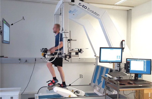
The standard G-EO system was augmented for this study with a visual biofeedback system (see Figure ) to allow each subject to perform volitional control of exercise work rate (power P); this human-in-the-loop volitional work rate controller is embedded within the overall heart rate controller structure (Figure ). The end-effector footplates are equipped as standard with four force sensors each; measurement of footplate velocity is also available within the G-EO control software. The force and velocity signals allow the rate of work done by the subject while pushing down and pulling up on the footplates to be calculated: this power is denoted . The measured work rate
is displayed to the subject in real time on the visual feedback screen together with a target work rate signal
. During a 10-min open-loop warm up phase, subjects were familiarized with the task of modifying the forces applied to the footplates to keep the actual work rate close to the target; all subjects were able to react appropriately to follow step changes in
. When feedback control of heart rate is operational, the target work rate
is continuously and automatically updated in real time as the output of the heart rate controller block (Figure ).
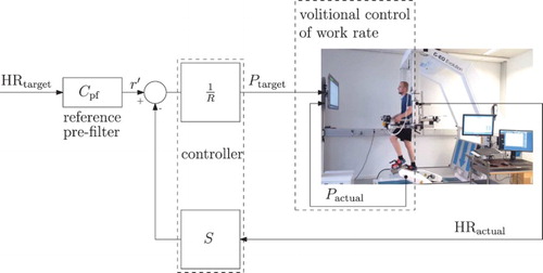
Figure 2. Overall control structure with inner human-in-the-loop volitional control of exercise work rate and outer loop for automatic feedback control of heart rate.
: target work rate.
: calculated actual work rate.
: target heart rate.
: measured heart rate.
The heart rate was measured using a chest belt monitor (model T34, Polar Electro Oy, Finland) and a receiver module (HRMI, Sparkfun Electronics, USA). The target heart rate
, which in general can be programmed as an arbitrary profile over time, was set as described below. Using
and
as inputs, the controller thus computed
for display to the subject.
The overall control structure was implemented in real time using Labview (National Instruments Inc., USA) and integrated directly within the G-EO's embedded control computer. Off-line calculation of controller parameters and post-test data processing were done using Matlab (MathWorks Inc., USA).
2.2. Subjects
Five healthy, able-bodied male subjects with no known cardiovascular, pulmonary or musculoskeletal problems participated in this study (see Table ). All subjects were informed about risks and benefits and gave written informed consent prior to participation. The Ethics Review Board of the Canton of Bern in Switzerland approved the study (Ref.: KEK-Nr. 155/12).
Table 1. Subject characteristics.
2.3. Test protocol
Each subject participated in two heart rate control tests, each carried out on a separate day: there was a command response test (step changes in target heart rate, constant stepping cadence) and a disturbance test (constant target heart rate, step changes in cadence). Both tests consisted of a 10-min warm up, a 10-min rest and a 35-min evaluation-phase (see Figure ). For all tests, a step height of 18 cm was used.
Figure 3. Test protocols. (a) command response test, (b) disturbance test. CD = stepping cadence.
Target heart rate was derived for each subject from an individual, age-related mid-level heart rate denoted
. This is defined as the heart rate at the transition between the moderate and vigorous training intensity regimes, and is given by
(Pescatello et al. Citation2014). Here, the individual age-predicted maximal heart rate is taken to be
(bpm) (Shargal et al. Citation2015).
The command response was tested using a target heart rate of bpm and a constant stepping cadence of 70 steps/min. Thus, target heart rate was changed periodically between a lower-level heart rate
bpm and a higher-level heart rate
bpm (protocol: Figure (a)).
The disturbance tests were conducted with a constant heart rate target of . A major disturbance was implemented in the plant by periodically changing the stepping cadence from
steps/min to
steps/min (protocol: Figure (b)). For subject S02, this change required intolerably large forces to be applied, therefore the disturbance test was repeated in this subject with
steps/min. The value 70 steps/min is considered to be the nominal cadence because plant model-identification experiments were conducted at this stepping rate.
2.4. Outcome measures and analysis
Feedback controller performance was evaluated using three primary outcome measures: root-mean-square error for heart rate tracking
(1) where
is the simulated output obtained from the nominal feedback loop; average power in changes in the control signal (target work rate
)
(2) and RMSE for volitional work rate control
(3) All three outcomes were calculated over an evaluation time interval from 300 s to 1800 s (5–30 min). This interval covers the period from 5 min before the first step change in target heart rate or cadence until 5 min after the final step change (see Figure ).
gives a quantitative measure for the accuracy of heart rate tracking and regulation, while
measures the intensity of control signal activity.
describes the accuracy of the subject's volitional control of target work rate.
2.5. Plant model and feedback design
With reference to the overall control structure (Figure ), the plant for design of the automatic heart rate controller can be considered to be the transfer function from the target work rate to the actual heart rate
. The plant thus includes the human-in-the-loop volitional work rate controller and the physiological response of the human body to the imposed work rate. This structure can be simply represented as a standard feedback control system, where the nominal plant is now given as the transfer function
(see Figure and Equation (Equation4
(4) )). In terms of generic signal descriptions, the reference signal r corresponds to the target heart rate
, the controlled variable (plant output) y is the actual heart rate
, the control signal u is the target work rate
, while the signal d has been introduced to represent plant output disturbances. In the context of heart rate control, the disturbance d principally models HRV, but, for the specific disturbance tests carried out in the present study, d can also be considered to model changes in stepping cadence.
Figure 4. Structure of the discrete-time heart rate feedback control system with pre-filter , feedback controller transfer function
and nominal plant
.
In line with previous recommendations (Hunt, Fankhauser, & Saengsuwan, Citation2015; Hunt & Fankhauser, Citation2016), the nominal plant is modelled here as a first-order linear time-invariant (LTI) system with steady-state gain k and time constant τ. This is represented in continuous or discrete time, respectively, as and
:
(4) The double arrow represents transformation between the continuous and discrete time domains with using a sample interval
. A and B are polynomials and, for the first-order case, the discrete model parameters
and
, in terms of k, τ and
, are
(5)
Model parameters k and τ were determined empirically using least-squares identification as the average values obtained from two subjects performing open-loop square wave tests. Of these two subjects, only one continued to the closed-loop heart rate controller evaluation (Subject S01 in Table ). In the identification tests, was a square wave of period 10 min and the exercise intensity was in the moderate-to-vigorous range. Averaging the two models obtained gave k=0.54 bpm/W and
s, and these nominal values are adopted in the sequel for calculation of the controller parameters.
The feedback part of the heart rate controller is developed in discrete time using the nominal discrete-time model , Equation (Equation4
(4) ). The compensator is taken to be the discrete LTI transfer function (see Figure )
(6) where S and R are polynomials.
For the application under consideration in the present work, it is particularly important to design the feedback part of the heart rate controller, C, to be insensitive to the HRV disturbance signal. This design requirement arises because the control signal u is the target work rate which is presented to the subject via the visual feedback system and which has to be attained using continuous adaptation of the volitional forces applied on the footplates: this target is much easier to achieve, both cognitively and physically, if the control signal is relatively smooth and of low intensity.
This fundamental performance requirement can be directly addressed by consideration of the closed-loop input sensitivity function, denoted , which describes the relationship between the HRV disturbance term d and the control signal u, viz.
(7) Denoting the closed-loop characteristic polynomial as
,
becomes
(8)
To meet the design requirements, the controller transfer function , Equation (Equation6
(6) ), is purposely constrained in three ways:
To ensure zero steady-state tracking error for constant command signals, integral action is implemented by inclusion of the factor
in the controller denominator polynomial
To make the control loop insensitive to HRV disturbances in the frequency range above the required loop bandwidth, the controller transfer function gain is required to roll off to zero at high frequency, that is,
Importantly, the low-pass character of C thus obtained also results in the input-sensitivity function
A further technique can be employed to obtain a relatively non-dynamic control signal: not shifting the open loop poles by the feedback (Åström & Murray, Citation2008). This is achieved by a cancellation strategy where the open-loop plant denominator polynomial
With
Under this constraint, with
Taken together, these three factors result in a constrained controller transfer function of the form
(11)
Employing , Equation (Equation4
(4) ), consideration of the reduced characteristic equation (Equation9
(9) ) shows that a unique minimal-degree solution for the unknown controller polynomials
and
is obtained with the degrees of
,
and
set to
and
, respectively (Åström & Wittenmark, Citation2011). The final form for the controller transfer function (Equation11
(11) ) is thus
(12) and the two closed-loop poles, in addition to the roots of
, are the roots of
(13) The algebraic equation to be solved for the controller coefficients is, from Equations (Equation9
(9) ) and (Equation13
(13) ),
(14) Comparison of the coefficients of like powers on each side of the above gives the unique solution
(15)
The two free poles from Equation (Equation13(13) ) are set using a time-domain specification of a 10–90% closed-loop rise time
and critical relative damping
. To achieve this, the appropriate values for the
coefficients are (Hunt & Hunt, Citation2016)
(16)
In order to decouple the command response from the relatively low-bandwidth feedback loop, a reference pre-filter was introduced (Figure ). The closed-loop transfer function from the filtered reference signal
to plant output y is
(17) Including the pre-filter, the overall closed-loop transfer function from the reference r to y is set to be the strictly causal function
, where the dynamics can be set by the denominator polynomial
. Using Equation (Equation17
(17) ), this specification results overall in
(18) which can be solved for
as
(19) Similarly to the two free poles for the feedback loop, the polynomial
was set to have degree 2,
(20) and its coefficients were calculated to give a 10–90% rise time
and critical relative damping using (cf. Equation (Equation16
(16) ))
(21)
2.6. Controller calculation
The plant model Equation (Equation4(4) ), as noted above, had steady-state gain k=0.54 and time constant
. For feedback control of heart rate, a sample interval
s is appropriate, for reasons detailed elsewhere (Åström & Wittenmark, Citation2011; Hunt & Fankhauser, Citation2016; Hunt & Hunt, Citation2016). Using Equations (Equation4
(4) ) and (Equation5
(5) ), these values result in parameters
,
and, therefore, the nominal discrete-time plant model
(22)
The desired rise time was chosen as s giving, Equation (Equation16
(16) ),
(23) and the controller coefficients, Equation (Equation15
(15) ),
(24) From Equation (Equation12
(12) ), the controller transfer function
is
(25)
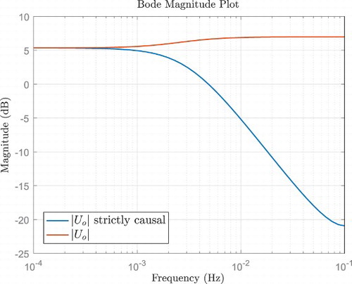
With these controller parameters, the gain of the input-sensitivity function has the desired low-pass characteristics (see Figure , blue line), thus making the feedback loop insensitive to HRV disturbances occurring at frequencies higher than the closed-loop bandwidth.
Figure 5. Input-sensitivity-function magnitude, , Equation (Equation10
(10) ). The blue line was computed using the strictly causal controller of Equation (Equation25
(25) ). The red line is for a non-strictly causal compensator as described in Results.
For design of the pre-filter , a command response rise time
s was chosen, which is considerably faster than the loop rise time
s. Because
, and using Equations (Equation13
(13) ), (Equation20
(20) ) and (Equation21
(21) ),
is obtained from Equation (Equation19
(19) ) as
(26)
3. Results
The results for all five subjects for the command response and disturbance tests showed satisfactory performance (Figure ): the command response tracking of heart rate target profiles was accurate and the control signal (target work rate) was smooth and well behaved in all cases (left column of plots in Figure ); all disturbance rejection tests showed that the controller was able to recover from and quickly eliminate the disturbances induced by the large step changes in stepping cadence (right column of plots in Figure ). As noted in the Methods, Section 2.3, disturbances were implemented in the plant by periodically changing the stepping cadence from steps/min to
steps/min, except for subject S02 where
steps/min was used. The red horizontal bars in Figure indicate the time interval from 300 to 1800 s (5–30 min) over which the formal outcome measures were evaluated (Table ).
Figure 6. Results of the reference tracking tests (left column) and disturbance rejection tests (right column). (a) S01, command response test. (b) S01, disturbance rejection test. (c) S02, command response test. (d) S02, disturbance rejection test. (e) S03, command response test. (f) S03, disturbance rejection test. (g) S04, command response test. (h) S04, disturbance rejection test. (i) S05, command response test. (j) S05, disturbance rejection test. (k) Legend for plots (a)–(j).
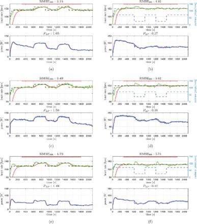
Figure 6. Continued
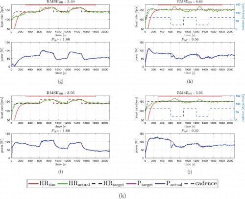
Table 2. Outcome measures for both test types.
This subjective behaviour was reflected in the objective, quantitative control-performance outcome measures (summary: Table ). For the command response tests, root-mean-square (RMS) tracking error for heart rate across the five subjects was bpm (mean ± standard deviation) with a range of 3.05 to 4.70 bpm. Average control signal power was
W2 (range 1.49 to 1.80 W2). For the disturbance tests, RMS tracking error was
bpm (range 4.92 to 6.66 bpm) and average control signal power was
W2 (range 0.27 to 0.56 W2).
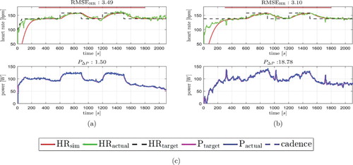
A further single case illustrates the importance of the imposed low-pass constraint for the controller and the input-sensitivity function in this application. Subject S02 was tested with a non-low-pass controller, resulting in a non-low-pass input-sensitivity function (red trace for in Figure ). The low-pass and non-low-pass results are juxtaposed in Figure . Analysis of the results with the non-low-pass controller gave RMS tracking error
bpm, average control signal power
W2 and
W. While the value
bpm is close to the low-pass value of 3.49 bpm for this subject (Table , S02) and lies within the overall range for all subjects of 3.05 to 4.70 bpm, average control signal power
is higher by a factor of ∼13 for this subject (1.50 vs. 18.78, low-pass vs . non-low-pass). This high level of activity in the control signal may make the volitional work rate control task more difficult for subjects. The RMS tracking error for work rate,
W, is outwith the range of 28.6 to 52.3 W observed across all five subjects with the low-pass controller (Table ).
Figure 7. Comparison of reference tracking tests for subject S02 with low-pass and non-low-pass control loop characteristics. (a) S02, C and low-pass. (b) S02, C and
non-low-pass. (c) Legend for plots (a) and (b).
4. Discussion
The aim of this work was to develop and test a novel heart rate control strategy for end-effector robots, operated in stair-climbing mode. Feedback design focused on dealing with disturbances caused by physiological HRV. This was achieved by appropriate shaping of the plant input-sensitivity function to give low-pass loop characteristics.
The command response tests for all subjects were accurate, with a mean RMS heart rate tracking error of 3.58 bpm. This value is slightly higher than previous reports of heart rate control which used a conventional treadmill: using a similar low-pass input-sensitivity-shaping approach, Hunt and Fankhauser (Citation2016) reported
bpm; using two non-low-pass control approaches, one linear and one nonlinear, Hunt and Maurer (Citation2016) reported
bpm. In common with the behaviour seen in the present work, the non-low-pass approach gave slightly lower RMSE, but at the expense of a very high average control signal power. The lower RMSE seen in these treadmill studies, in comparison to the end-effector robot application, is probably due the fact that the treadmill does not require the subject to be involved in volitional control of the target variable computed by the controller: for the treadmill, the control signal is the treadmill speed which is set automatically by the motor; for the end-effector robot, it is the target work rate, which has to be maintained by the subject. The higher RMSE seen in the present work is likely also due in part to the lower bandwidth in this case; this was purposely selected to ease the subjects' task of maintaining the target work rate.
The disturbance tests demonstrated rapid rejection of heart rate deviations induced by large step changes in stepping cadence. All of these tests (Figure , right column) showed a similar pattern of response. For a step down in cadence, there was a rapid initial drop in the subject's work rate, taking it well below the work rate target. This was presumably due to the subject initially maintaining a similar level of force to that used immediately before the change in cadence (a lower cadence necessitates a higher force for a given work rate). The subject then rapidly increased force to regain the work rate target. This in turn caused the heart rate to rise substantially above the target heart rate, leading to the controller automatically reducing the target work rate to compensate the disturbance. This initial rise in heart rate, followed by a reduction in target work rate, points to the exercise at the lower cadence being metabolically less efficient, because, under steady-state conditions, it is clearly seen that the same heart rate is achieved at the lower cadence with a substantially lower work rate. The step changes from lower to higher cadence demonstrated converse behaviour, that is, the responses were symmetric. The disturbance rejection results show similar behaviour across all subjects, with low dispersion (standard deviation) of and
.
The single LTI controller used unaltered in all tests with all five subjects demonstrated good robustness. The results were consistent across subjects for both types of test, with low dispersion of all outcome variables. The LTI controller was designed using an approximate plant model. This nominal model was the average of two models obtained from identification tests with two subjects, only one of whom (S01) participated in the feedback control tests, therefore the model was not specific to any of the five subjects tested. These observations lend support to previous proposals that dealing with the HRV disturbance is the key design challenge for heart rate control, rather than issues of parametric and structural plant uncertainty (Hunt & Fankhauser, Citation2016).
The results showed that HRV is suppressed in certain frequency ranges by appropriate shaping of the input-sensitivity function (low-pass characteristics) to give low control signal power. The single result with a non-low-pass controller showed that, while can be slightly reduced, average control signal power
can be inflated to an unacceptable level (Figure , right side).
5. Conclusions
The results demonstrate the feasibility of the proposed heart rate control strategy for end-effector robots. The controller showed consistent behaviour for command response and disturbance rejection tasks for all five subjects. Robustness was proven since the single LTI controller was based on a nominal model which was not specific to any of the subjects tested. Physiological HRV appears to be the principal feedback design issue for heart rate control, while parametric/structural plant uncertainty is secondary.
The observed control performance is considered satisfactory for the able-bodied subjects studied here. To evaluate clinical feasibility, future studies of the proposed approach should be conducted with target groups of patients with neurological disorders. This may lead to the identification of modifications to or improvements in the control strategy.
Authors' contributions
JR and KH designed the study. JR did the data acquisition. JR and KH contributed to the analysis and interpretation of the data and to writing of the manuscript. Both authors read and approved the final manuscript.
Acknowledgments
The authors gratefully acknowledge the following contributions to this work: Matthias Schindelholz developed the user interface and the Labview structures for the controllers; Jeanny A. Kaiser contributed to the data acquisition for plant model identification.
Disclosure statement
No potential conflict of interest was reported by the authors.
ORCiD
Kenneth J. Hunt http://orcid.org/0000-0002-6521-9455
References
- Åström, K. J., & Murray, R. M. (2008). Feedback systems. Princeton: Princeton University Press.
- Åström, K. J., & Wittenmark, B. (2011). Computer controlled systems: Theory and design (3rd ed.). New York, NY: Dover.
- Buijs, R. M., & Swaab, D. F. (Eds.). (2013). Handbook of clinical neurology. Vol. 117: Autonomic nervous system. Amsterdam: Elsevier.
- Cheng, T. M., Savkin, A. V., Celler, B. G., Su, S. W., & Wang, L. (2008). Nonlinear modeling and control of human heart rate response during exercise with various work load intensities. IEEE Transactions on Biomedical Engineering, 55(11), 2499–2508. doi: 10.1109/TBME.2008.2001131
- Garber, C. E., Blissmer, B., Deschenes, M. R., Franklin, B. A., Lamonte, M. J., Lee, I. M., … Swain, D. P. (2011). American College of Sports Medicine position stand. Quantity and quality of exercise for developing and maintaining cardiorespiratory, musculoskeletal, and neuromotor fitness in apparently healthy adults: Guidance for prescribing exercise. Medicine & Science in Sports & Exercise, 43(7), 1334–1359. doi: 10.1249/MSS.0b013e318213fefb
- Go, A. S., Mozaffarian, D., Roger, V. L., Benjamin, E. J., Berry, J. D., Borden, W. B., … Turner, M. B. (2013). Heart disease and stroke statistics-2013 update: A report from the American Heart Association. Circulation, 127(1), e6–e245. doi: 10.1161/CIR.0b013e31828124ad
- Hesse, S., Tomelleri, C., Bardeleben, A., Werner, C., & Waldner, A. (2012). Robot-assisted practice of gait and stair climbing in nonambulatory stroke patients. Journal of Rehabilitation Research and Development, 49(4), 613–622. doi: 10.1682/JRRD.2011.08.0142
- Hesse, S., Waldner, A., & Tomelleri, C. (2010). Innovative gait robot for the repetitive practice of floor walking and stair climbing up and down in stroke patients. Journal of NeuroEngineering and Rehabilitation, 7:30. doi: 10.1186/1743-0003-7-30
- Hunt, K. J., & Fankhauser, S. E. (2016). Heart rate control during treadmill exercise using input-sensitivity shaping for disturbance rejection of very-low-frequency heart rate variability. Biomedical Signal Processing and Control, 30, 31–42. doi: 10.1016/j.bspc.2016.06.005
- Hunt, K. J., Fankhauser, S. E., & Saengsuwan, J. (2015). Identification of heart rate dynamics during moderate-to-vigorous treadmill exercise. BioMedical Engineering OnLine, 14:117. doi: 10.1186/s12938-015-0112-7
- Hunt, K. J., & Hunt, A. J. R. (2016). Feedback control of heart rate during outdoor running: A smartphone implementation. Biomedical Signal Processing and Control, 26, 90–97. doi: 10.1016/j.bspc.2016.01.001
- Hunt, K. J., & Maurer, R. R. (2016). Comparison of linear and nonlinear feedback control of heart rate for treadmill running. Systems Science & Control Engineering, 4(1), 87–98. doi: 10.1080/21642583.2016.1179139
- Kawada, T., Sunagawa, G., Takaki, H., Shishido, T., Miyano, H., Miyashita, H., … Sunagawa, K. (1999). Development of a servo-controller of heart rate using a treadmill. Japanese Circulation Journal, 63, 945–950. doi: 10.1253/jcj.63.945
- Kolominsky-Rabas, P. L., & Heuschmann, P. U. (2002). Incidence, etiology and long-term prognosis of stroke. Fortschritte der Neurologie-Psychiatrie, 70(12), 657–662. doi: 10.1055/s-2002-35857
- Pescatello, L. S., Arena, R., Riebe, D., & Thompson, P. D. (Eds.). (2014). ACSM's guidelines for exercise testing and prescription (9th ed.). Philadelphia, PA: Lippincott, Williams and Wilkins.
- Scalzi, S., Tomei, P., & Verrelli, C. M. (2012). Nonlinear control techniques for the heart rate regulation in treadmill exercises. IEEE Transactions on Biomedical Engineering, 59(3), 599–603. doi: 10.1109/TBME.2011.2179300
- Schindelholz, M., & Hunt, K. J. (2012). Feedback control of heart rate during robotics-assisted treadmill exercise. Technology and Health Care, 20(3), 179–194.
- Shargal, E., Kislev-Cohen, R., Zigel, L., Epstein, S., Pilz-Burstein, R., & Tenenbaum, G. (2015). Age-related maximal heart rate: Examination and refinement of prediction equations. The Journal of Sports Medicine and Physical Fitness, 55(10), 1207–1218.
- Stoller, O., Schindelholz, M., Bichsel, L., & Hunt, K. J. (2014). Cardiopulmonary responses to robotic end-effector-based walking and stair climbing. Medical Engineering & Physics, 36(4), 425–431. doi: 10.1016/j.medengphy.2013.12.016
- Stoller, O., Schindelholz, M., & Hunt, K. J. (2016). Robot-assisted end-effector-based stair climbing for cardiopulmonary exercise testing: Feasibility, reliability and repeatability. PLoS ONE, 11(2):e0148932. doi: 10.1371/journal.pone.0148932
- Su, S. W., Huang, S., Wang, L., Celler, B. G., Savkin, A. V., Guo, Y., & Cheng, T. M. (2010). Optimizing heart rate regulation for safe exercise. Annals of Biomedical Engineering, 38(3), 758–768. doi: 10.1007/s10439-009-9849-0
- Westlake, K. P., & Patten, C. (2009). Pilot study of lokomat versus manual-assisted treadmill training for locomotor recovery post-stroke. Journal of NeuroEngineering and Rehabilitation, 6:18. doi: 10.1186/1743-0003-6-18