
 ?Mathematical formulae have been encoded as MathML and are displayed in this HTML version using MathJax in order to improve their display. Uncheck the box to turn MathJax off. This feature requires Javascript. Click on a formula to zoom.
Abstract
Two-wheeled self-balancing robots (TWSBR) is a highly nonlinear and inherently unstable under-driving system. When controlling its movement on an inclined surface, it is more difficult than when it is on a level road. This paper proposes a fuzzy fractional-order PID (FFOPID) controller for the motion control of a TWSBR system in an inclined environment. The control goal of TWSBR is to realize the wheel position control and to stabilize the non-vertical direction of intermediate body (IB). Finally, we compare the control effect of the proposed FFOPID controller with that of the integer-order PID controller, the fuzzy PID (FPID) controller, and the fractional-order PID (FOPID) controller when TWSBR moving on the inclined plane. The simulation results show that the FFOPID controller has better control performance and anti-interference ability.
1. Introduction
TWSBR is usually composed of two wheels and the intermediate body (IB). Comparing with multiwheeled robot, TWSBR has some advantages, such as turning in place, small structure, flexible movement and so on Wang et al. (Citation2018). TWSBR system is a typical nonlinear system, which has many factors, such as multi-variable, inherent instability, under-actuated and non-holonomic constraints. Therefore, TWSBR has become an ideal platform to verify advanced control algorithms. The goal of the controller is to realize the position control of the robot and the balance control of the IB.
In view of the stability control problem of TWSBR on the horizontal ground, the existing literature has proposed many types of controller design schemes. The traditional PID controller is proposed in Lee and Lee (Citation2012) and Juang and Lum (Citation2013). Linear quadratic regulator (LQR) (Prasad et al., Citation2012) controller and pole assignment method (Siradjuddin et al., Citation2017) can control the position of robot or the vertical stability of IB without steady-state error. Due to the poor control effect of PID controller on the system with high order and extra noise, in these literatures (Bingul & Karahan, Citation2011; Kumar & Dinesh, Citation2014; Paliwal, Citation2017; Singh, Citation2015), based on the integer-order PID controller, the FOPID controller is designed for TWSBR system. Comparing with the former, the latter adds two adjustable parameters, which expand the parameter tuning range and improves the control ability. In view of the good nonlinear approximation ability of fuzzy controller, it is often used alone or combined with other controllers to form a composite controller, and then applied to TWSBR system to improve the control ability of the controller, just to take a few examples (Jian et al., Citation2018; Paliwal et al., Citation2016; Qiu, Citation2015; Shi et al., Citation2020; Wu & Zhang, Citation2011; Wu et al., Citation2012).
The above methods are only for balancing robots moving on horizontal plane. However, in reality, TWSBR's motion environment is more on uneven road, including sloping road, undulating road and irregular road. The research in this paper is to control the position and balance of the robot in a sloping road environment. When TWSBR is stable on the inclined road, there is a fixed angle between the IB and the vertical axis, which is related to the ground inclination angle, and the wheel torque is not equal to zero (Kausar et al., Citation2012). In Liang et al. (Citation2017) and Peng et al. (Citation2012), they established the dynamic model of the robot on the inclined road with Lagrange method and designed the linear controller with LQR method after getting the equilibrium state, while the overshoot is very large at the beginning. In Huang et al. (Citation2010), a sliding mode controller is designed for the speed tracking problem of TWSBR system, which basically realizes the speed tracking control under the condition of unknown ground inclination. A new Takagi-Sugeno fuzzy logic controller is designed in Xu et al. (Citation2013), which implements TWSBR position control and verifies the effectiveness of the controller through experiments. It is worth noting that the control effect of type-1 fuzzy controller is not particularly prominent when the system is uncertainty. Therefore, on the basis of the previous robot model, the authors of Dian et al. (Citation2019) are designed and applied a generalized type-2 T-S fuzzy balance controller to achieve the balance control of TWSBR and designed a generalized type-2 Mamdani fuzzy position controller to make TWSBR reach the set position. The simulation results show that the controller has good control effect.
Due to the new λ and µ two adjustable parameters, FOPID controller increases the parameter tuning range, and thus the control performance is better than the integer-order PID controller (Paliwal, Citation2017). According to the investigation of the existing literature, FFOPID controller is superior to the traditional controller in the control performance and robustness in the field of power control and manipulator control (Barbosa & Jesus, Citation2013a; George et al., Citation2021; Sharma et al., Citation2018). According to the literature survey, FFOPID controller has not been used in position and balance control of TWSBR. In this paper, combining the advantages of Fuzzy Logic Controller (FLC) and FOPID controller, a FFOPID controller suitable for TWSBR control of slope roads is designed. By adding new parameters in the fractional-order controller and increasing the parameter tuning range, FLC can adjust the fractional-order parameters online and improve the control quality and anti-interference ability. The contributions of the current work are described below:
Combining the advantages of FOPID and FLC, the FFOPID controller is designed to achieve dual control of the position and balance of TWSBR when it moves on a sloping road.
The FLC in the FPID and FFOPID controllers is one of the difficult points in the design. Based on the control experience of the self-balancing robot, the fuzzy rule library and the membership function are redesigned.
The PID, FPID, FOPID and FFOPID controllers are studied, respectively, and these controllers are used to control the position and stability of the TWSBR moving on the slope.
In the simulation experiment, two slope environments with different inclination and two disturbance conditions are designed to compare the performance of the four controllers. The results show that the FFOPID controller has good control effect and anti-disturbance ability.
The other parts of this paper are as follows. In Section 2, the dynamic model of TWSBR on the inclined plane is introduced. Section 3 mainly introduces the design process of FFOPID controller, briefly explain the other three controllers. In Section 4, the simulation tests on the controller are performed to verify the effectiveness of the FFOPID controller. The conclusions and future work are drawn in Section 5.
2. Dynamic model on the slopes
2.1. TWSBR model
Figure is a sectional view of the TWSBR dynamic model on an inclined road surface (Xu et al., Citation2014). In this paper, the wheel is always in contact with the inclined plane, and there is no sliding phenomenon. The displacement and velocity of the robot are defined as x and . θ is the inclination angle of the IB, with the vertical direction as the zero point, and the angle is positive when rotating clockwise.
is the angular velocity of rotation. φ indicates the angle between the inclined road surface and the horizontal plane. u is the output torque of the drive motor and the input of TWSBR system. When u is positive, it means that the motor rotates clockwise; when the number is negative, it means that the motor rotates counterclockwise. f is the friction between the wheel and the ground.
refers to the rolling resistance between the wheel and the road surface. F is the interaction force between the IB and the wheel in the inclined plane component. The direction indicated by a single arrow indicates the direction of motion when the relevant parameter is positive. In this paper, the system is regarded as an ideal state temporarily, that is,
and f are both zero. Due to the small mass and volume of the robot, there is no requirement for the characteristics of the inclined road surface in the simulation experiment. The parameters of the robot are shown in Table .
Figure 1. Model of the TWSBR.
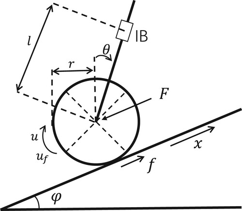
Table 1. Robot parameters.
Lagrange method is used to establish the dynamic model of the two-wheeled self-balancing robot. The following formula is derived, the Lagrange function scalar is defined as the difference between the kinetic energy and potential energy of the system (Liang et al., Citation2017):
(1)
(1) where T, V are the total kinetic and potential energy of the TWSBR, respectively. T consists of four parts: the wheel moving kinetic energy, the wheel rotating kinetic energy, the kinetic energy of movement of IB and the kinetic energy of rotation of IB; V contains the potential energy of body and wheel. The kinetic energy of the IB is expressed as follows:
(2)
(2) The rotational kinetic energy of the IB is
, the kinetic energy of the wheel is
, the rotational kinetic energy of the wheel are as follows (
,
is the speed of the left and right wheels) :
(3)
(3) The total potential energy V:
(4)
(4) Substitute Equations (Equation2
(2)
(2) )–(Equation4
(4)
(4) ) into Equation (Equation1
(1)
(1) ) yields:
(5)
(5) According to the force relationship shown in Figure , the differential equations for wheel displacement and vehicle body inclination can be obtained by taking the derivative of the Lagrangian equation, as shown below:
(6)
(6) Substituting Equations (Equation5
(5)
(5) ) into (Equation6
(6)
(6) ) to obtain the second-order nonlinear model of TWSBR on the inclined plane:
(7)
(7)
(8)
(8) Define the state variable vector:
(9)
(9) According to Equations (Equation7
(7)
(7) )–(Equation9
(9)
(9) ), the state space expression of TWSBR is derived:
(10)
(10) where
and
.
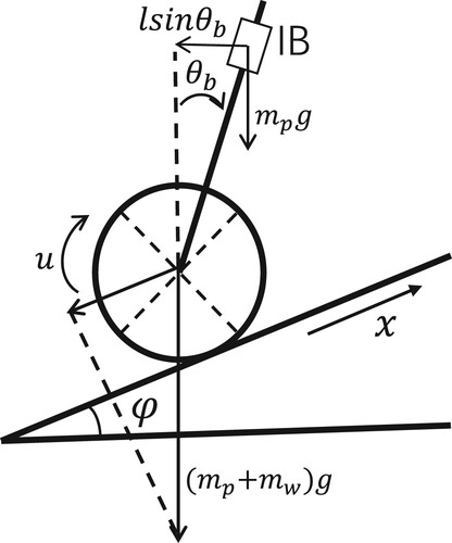
2.2. Systematic analysis in steady state
When TWSBR is stable on an inclined road surface, as shown in Figure , =0,
=0 and
=0, substituting in the formula (Equation7
(7)
(7) ) (Equation8
(8)
(8) ), the following equation are obtained:
(11)
(11)
(12)
(12) From the above equation, it can be concluded that:
(13)
(13) where
is the inclination angle of the robot when it is stable on the inclined road, the inclination angle is only determined by the ground tilt angle, and the other parameters are the robot's own parameters. Equation (Equation11
(11)
(11) ) is the torque provided by the wheels when the robot is stabilized to counteract the effect of gravity.
Figure 2. Diagram of balance state.
3. Controller design
This section will introduce the design and implementation of the FFOPID controller in detail. Briefly introduce the design of FOPID, PID and FPID controller.
3.1. FOPID controller
FOPID was first proposed by professor Podlubny (Citation1999). Compared with the integer-order PID controller, it adds two variable parameters, λ-order integral and µ-order derivative. The general form is denoted as , and the control action can be described by Equation (Equation14
(14)
(14) ).
(14)
(14) In this paper,
(α = -λ, µ) is used to represent the component number order operator, and a simple G-L definition is used to solve the fractional-order operator (Barbosa & Jesus, Citation2013b):
(15)
(15)
(16)
(16) The output equation of discrete FOPID controller is as follows:
(17)
(17) where
is binomial coefficient, the simplified expression is as follows:
(18)
(18) The recurrence formula is as follows:
(19)
(19) when the step size T is very small, the approximate value of fractional calculus can be obtained directly according to the recursive formula.
3.2. PID controller
The standard PID control equations and traditional functions are expressed as follows:
(20)
(20) Comparing the transfer functions of the two controllers, it can be seen that the four common types of PID controllers (P, PI, PD, PID) are all special cases of FOPID controllers. For example, when
, the FOPID controller degenerates into a regular integer-order PID controller.
3.3. FPID controller
The principle of converting FFOPID to FPID is the same as that of degenerating FOPID to PID. As shown in Figure , if the fractional integral operator and the differential operator
in the FFOPID controller, then the FPID controller is obtained.
Figure 3. Schematic diagram of FFOPID controller.
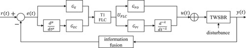
3.4. Design of FFOPID controller
Figure is the structure block diagram of the FFOPID controller. In this paper, the integrator/differentiator is set to a fractional-order form based on the relatively simple fuzzy PD and fuzzy PI parallel FPID controller structure to obtain the FFOPID controller. Taking the error and fractional-order error as the input of the FLC. and
are the input scaling factor,
and
are the output scaling factor, λ and µ are fractional orders. They are all optimization variables in particle swarm optimization (PSO) algorithm.
According to the schematic diagram, the controller output u can be expressed by Equation (Equation21(21)
(21) ):
(21)
(21) Due to the characteristics of the fuzzy controller, it can be concluded that the control law
of the fuzzy logic controller is a nonlinear function of the error and the fractional derivative of the error. The input and output of the FLC are usually a nonlinear complex mapping relationship, where the function f represents a nonlinear function. Use the linear approximation method (Jantzen, Citation1998) to process f into a linear function. Then the control rate u is expressed as:
(22)
(22) Compared with (Equation14
(14)
(14) ), the scaling factor in FFOPID controller is defined as follows:
is the proportional term,
is a fractional differential term,
is a fractional integral term,
is a fractional-order action term. Whether it is a fractional integral term or a fractional differential term depends on the size of λ and µ.
There is an information fusion link in the structure diagram. Since TWSBR system has four variables, in order to prevent the explosion of designing multiple FLC and fuzzy rules, the information fusion method is used to fuse the four state variables into two variables, which reduces the difficulty of controller design. The specific process of information fusion is as follows:
A state feedback gain matrix
is constructed. In the previous section, the state space model of the self-balancing robot nonlinear system has been derived, and the state feedback matrix
The fusion matrix
Error e and error change rate ec are obtained by parameter fusion.
According to the structure of the controller, only the error e is used in the input. After fusion, the input of the controller still contains all the information of position and tilt angle, which reduces the variable dimension and the difficulty of controller design.
The error (e) and fractional derivative of error () are selected as the inputs of the controller. Figure shows the membership function of input, which is divided into three linguistic variables, namely, negative small (NS), zero (ZO) and positive small (PS). Fuzzy logic rules are usually set according to expert knowledge and practical experience. In this paper, the logic rules are summarized through practical experience. For example, at the beginning, there is a big difference between the set value and the target value, which needs to produce a large control output. At this time,
and
choose the larger value,
select the smaller value. When moving to the target value, in order to reduce the steady-state error,
and
choose the smaller value,
select the larger value. Therefore, the fuzzy rule table is shown in Table .
Figure 4. Membership function – error signal, fractional order of error.
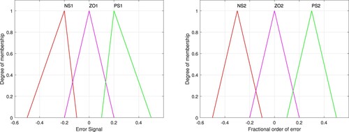
Table 2. Rule based for /
/
.
The next section applies the FFOPID controller into the TWSBR system to realizes the position and balance control and gives the corresponding numerical simulation.
4. Simulation results and analysis
The proposed FFOPID controller is simulated on the MATLAB platform and applied to the position and stability control of the TWSBR. The control effect and robustness are compared with those of FOPID, PID and FPID controllers. In order to quantitatively compare the performance index parameters of the four controllers, three evaluation functions ISE, IAE and ITAE are used in this section to comprehensively evaluate the control performance of the controller. Definition of evaluation function index (Lin et al., Citation2010):
(25)
(25) The weighting matrix Q, R and state feedback matrix K (Xu et al., Citation2013) and fusion matrix
are used in the simulation experiment are as follows:
(26)
(26) The initial value of the TWSBR is set as
, and the function of the controller is to control the robot to move to the target balance point
(
refers to the self-inclination angle of the balancing robot when it moves stably on the inclined plane). Particle swarm optimization (PSO) algorithm is used to optimize the parameters of FFOPID, FOPID, FPID and PID controller, including
,
,
,
, λ and µ. The optimized parameters in shown Table .
Table 3. Optimal parameters of controller.
4.1. Position and balance control
In the first case, we first set the slope angle , according to Equation (Equation11
(11)
(11) ) and (Equation13
(13)
(13) ), when the robot tends to be stable,
rad, control rate
N.m. The simulation results are shown in Figure ; Figure (a,b) show the changes of x and θ of the system with the participation of four controllers, and Figure (c) shows the output of the FFOPID controller. In Figure (a), the reason why the robot moves in the opposite direction at the beginning is that the torque is too large at the beginning. In order to prevent the IB from falling, the robot moves in the opposite direction to the target until the IB tilts to the target again. The four controllers can realize the position and balance control of TWSBR, but the stabilization time is different. The tilt angle of
approaches 0.1058 rad, and the control rate is close to 0.2156 N.m, which is consistent with the theoretical calculation.
Figure 5. When , the robot's position and balance performance on the inclined plane. (a) Position control of the robot. (b) Balance control of the robot and (c) The output of the FFOPID controller.
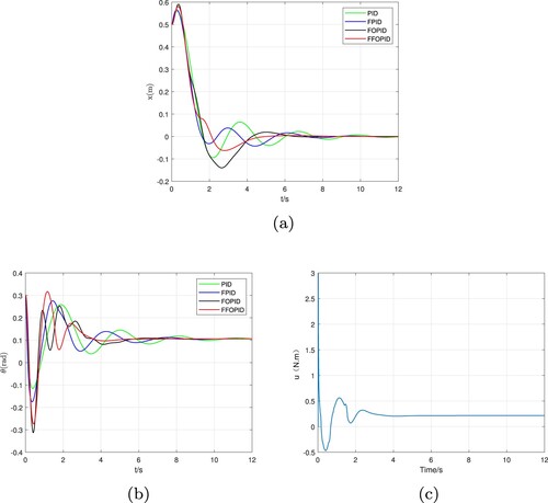
According to Figure and Table , the performance of the PID controller is the worst, which is characterized by the largest oscillation during the motion process and a longer stabilization time; secondly, the system reduces the oscillation under the parameters of the FPID controller and stabilizes earlier time; The FOPID controller has good performance, but the overshoot is larger in position control; Compared with the FOPID controller, FFOPID has the same settling time, but the oscillation is smaller and the performance is the best.
Table 4. The performance index result under the condition of .
In the second case, we change the tilt angle and set . When TWSBR stabilizes, at this time
rad, control rate u = 0.4156 N.m. It can be seen from the Figure that when TWSBR stabilizes on the slope, the inclination angle
tends to 0.2120 rad, and the control rate tends to 0.4156 N.m, which is consistent with the theoretical calculation.
Figure 6. When , the robot's position and balance performance on the inclined plane. (a) Position control of the robot. (b) Balance control of the robot and (c) The output of the FFOPID controller.
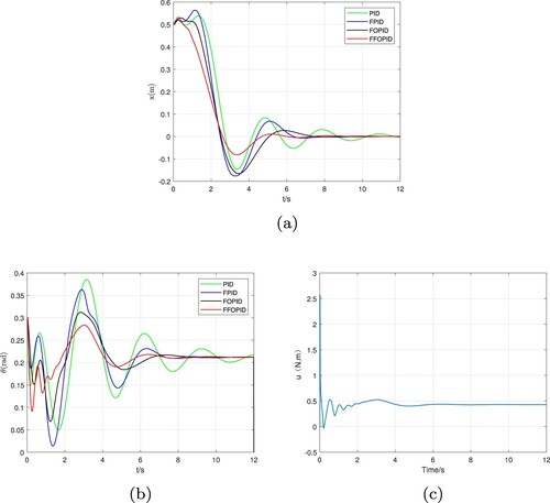
Figure (a,b) shows the changes of x and θ of the system with the participation of four controllers, and Figure (c) shows the output of the FFOPID controller. In Figure (a), the movement in the opposite direction at the beginning is caused by the excessive torque at the beginning. Compared with the former case, the angle of the inclined road is larger, and the movement in the opposite direction is more obvious. Combined with Figure and Table , the system has a large oscillation phenomenon in the whole dynamic motion process with the participation of the other three controllers. With the participation of the FFOPID controller, TWSBR is superior to the other three controllers in terms of position movement and time to stabilize.
Table 5. The performance index result under the condition of .
4.2. Anti-disturbance performance
To verify the anti-random disturbance performance of the proposed controller, a random disturbance of is added to the TWSBR system to simulate the internal disturbance caused by inaccurate derivation of the system dynamic model. Figure shows the performance of the four controllers in position and balance control in the case of two inclined planes. Since the random disturbance is added to the state space model of the system, the stability value changes with the disturbance. The system manifests that the robot oscillates in a certain range above and below the theoretical position and the balance tilt angle to maintain dynamic stability. In the case of disturbance, the control performance of the four controllers for TWSBR system is compared.
Figure 7. After adding disturbance, the robot's position and balance performance on the inclined plane. (a)
and (b)
.
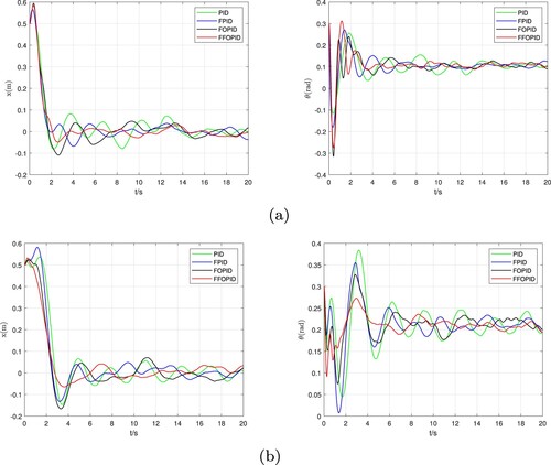
In the experiment, in order to avoid the incompatibility of performance between controllers caused by random numbers, after adding random interference, various controllers are tested for 10 times, and the best result is the final result. Combined with Figure and the Tables and , since the input of the PID controller is directly an error, it is most affected by the disturbance, and the system shows a great shock. Because of the addition of two adjustable parameters, the FOPID controller is better than the traditional PID controller in terms of disturbance performance. The FPID controller uses manual control experience to fuzzify the error within a certain range, so as to effectively adjust the system output. The result also proves that its controller effect is better than the previous two controllers. The FFOPID controller mentioned in this article combines the advantages of the FPID and FOPID controllers. It is mainly manifested in the smallest dynamic swing amplitude of the robot, especially in the case of a large tilt angle, the swing amplitude is significantly smaller than that of the other three controllers. The system also shows that the controller has good anti-random disturbance ability.
Table 6. When , performance index under the condition of
disturbance.
Table 7. When , performance index under the condition of
disturbance.
Next, we consider another kind of interference, adding a signal of 0.5 rad to the state variable in the ninth second to simulate when the robot is in a stable state, its tilt angle state quantity
suddenly receives an amplitude magnitude pulse interference of 0.5 rad. Figure shows the control performance of the four controllers under disturbance interference when
and
. Tables and shows the performance index results of the four controllers under two disturbance conditions.
Figure 8. After adding 0.5 rad interference, the robot's position and balance performance on the inclined plane. (a) and (b)
.
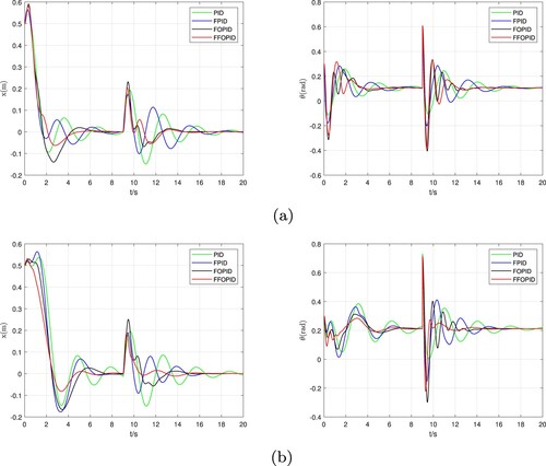
Table 8. When , performance index under the condition of 0.5 rad disturbance.
Table 9. When , performance index under the condition of 0.5 rad disturbance.
When the system is affected by instantaneous disturbance, the performance of the traditional PID controller is obviously insufficient. It can be seen that the position changes greatly, and the time to stabilize is the longest. With the participation of FPID and FOPID controllers, the system will produce a larger oscillation process when it is disturbed, but the overall performance of the controller is better than that of the PID controller. Combined with the controller performance indicators, with the participation of the FFOPID controller, the robot displacement change is small, the dynamic process vibration is small, and the system performs better in the case of instantaneous disturbances, indicating that the FFOPID controller participates in the system's anti-interference ability better.
5. Conclusion
Based on the derivation of TWSBR dynamic equation on inclined surface, the fusion function is used to reduce the input parameters of the system and prevent the explosion of fuzzy rules. The FFOPID controller is designed to achieve the position and balance control of TWSBR when it moves on inclined pavement. The simulation results show that the TWSBR system with the participation of FFOPID controller has smaller overshoot, shorter motion time and better anti-interference performance. The future work is to apply the controller proposed in this article to the Arduino self-balancing robot to verify the actual control effect of the controller. Secondly, for more complex and more realistic terrain conditions, the fuzzy rules, membership functions and controller parameters in the FFOPID controller are designed to realize the position and balance control of the TWSBR system in a complex road environment.
Disclosure statement
No potential conflict of interest was reported by the author(s).
Data availability statement
The datasets generated during and/or analysed during the current study are available from the corresponding author on reasonable request.
Additional information
Funding
References
- Barbosa, R. S., & Jesus, I. S. (2013a). Comparative study of fuzzy integer and fractional PID controller. In IECON 2013 – 39th annual conference of the IEEE industrial electronics society (pp. 3392–3397).
- Barbosa, R. S., & Jesus, I. S. (2013b). A methodology for the design of fuzzy fractional PID controllers. In ICINCO 2013 – 10th international conference on informatics in control, automation and robotics.
- Bingul, Z., & Karahan, O. (2011). Tuning of fractional PID controllers using PSO algorithm for robot trajectory control. In 2011 IEEE international conference on mechatronics (pp. 955–960).
- Dian, S. Y., Liang, W. B., & Zhao, T. (2019). Interval type-2 fuzzy logic control for a two-wheeled mobile robot based on improved QPSO. Kongzhi yu Juece/Control and Decision, 34(2), 261–268.
- George, M. A., D. V. Kamat, & Kurian, C. P. (2021). Electronically tunable ACO based fuzzy FOPID controller for effective speed control of electric vehicle. IEEE Access, 9, 73392–73412. https://doi.org/10.1109/ACCESS.2021.3080086
- Huang, J., Guan, Z.-H., Matsuno, T., Fukuda, T., & Sekiyama, K. (2010). Sliding-mode velocity control of mobile-wheeled inverted-pendulum systems. IEEE Transactions on Robotics, 26(4), 750–758. https://doi.org/10.1109/TRO.2010.2053732
- Jantzen, J. (1998). Tuning of fuzzy PID controllers.
- Jian, H., Ri, M. H., Wu, D., & Ri, S. (2018). Interval type-2 fuzzy logic modeling and control of a mobile two-wheeled inverted pendulum. IEEE Transactions on Fuzzy Systems, 26(4), 2030–2038. https://doi.org/10.1109/TFUZZ.91
- Juang, H. S., & Lum, K. Y. (2013). Design and control of a two-wheel self-balancing robot using the arduino microcontroller board. In 2013 10th IEEE international conference on control and automation (ICCA).
- Kausar, Z., Stol, K., & Patel, N. (2012). The effect of terrain inclination on performance and the stability region of two-wheeled mobile robots. International Journal of Advanced Robotic Systems.
- Kumar, M. S., & Dinesh, C. (2014). Stabilization and tracking control of inverted pendulum using fractional order PID controllers. Journal of Engineering, 1–9.
- Lee, H., & Lee, J. M. (2012). Driving control of mobile inverted pendulum. In 2012 9th International conference on ubiquitous robots and ambient intelligence (URAI).
- Liang, D., Ning, S., Wu, Y., & Fang, Y. (2017). Modeling and motion control of self-balance robots on the slope. In 2016 31st Youth academic annual conference of chinese association of automation (YAC).
- Lin, W., Zheng, S., Wang, X., & Fan, L. (2010). Fuzzy control of a double inverted pendulum based on information fusion. In International conference on intelligent control and information processing.
- Paliwal, S. (2017). Stabilization of mobile inverted pendulum using fractional order PID controllers. In 2017 International conference on innovations in control, communication and information systems (ICICCI) (pp. 1–4).
- Paliwal, S., Chopra, V., & Singla, S. K. (2016). Stabilization of mobile inverted pendulum using fuzzy PID controllers. In 2016 7th India international conference on power electronics (IICPE) (pp. 1–4).
- Peng, K., Ruan, X., & Zuo, G. (2012). Dynamic model and balancing control for two-wheeled self-balancing mobile robot on the slopes. In Proceedings of the 10th world congress on intelligent control and automation (pp. 3681–3685).
- Podlubny, I. (1999). Fractional-order systems and pi/sup/spl lambda//d/sup/spl mu//-controllers. IEEE Transactions on Automatic Control, 44(1), 208–214. https://doi.org/10.1109/9.739144
- Prasad, L. B., Tyagi, B., & Gupta, H. O. (2012). Modelling and simulation for optimal control of nonlinear inverted pendulum dynamical system using PID controller and LQR. In 2012 Sixth Asia modelling symposium.
- Qiu, C. (2015). The design of fuzzy adaptive pid controller of two-wheeled self-balancing robot. International Journal of Information and Electronics Engineering, 5(3). https://doi.org/10.7763/IJIEE.2015.V5.529
- Sharma, R., Joshi, D., & Gaur, P. (2018). A study on different configurations of fractional order fuzzy logic controller scheme for robotic manipulator using NSGA-II. In 2018 8th IEEE India international conference on power electronics (IICPE) (pp. 1–6).
- Shi, B., Xu, S., & Zhao, G. (2020). Variable universe type-ii fuzzy logic control design for the googol's two-wheeled self-balancing robot. In 2020 Chinese automation congress (CAC).
- Singh, A. P. (2015). Fractional order controller design for inverted pendulum on a cart system (POAC). WSEAS Transactions on Systems and Control, 10, 172–178.
- Siradjuddin, I., Amalia, Z., Setiawan, B., Wicaksono, R. P., & Yudaningtyas, E. (2017). Stabilising a cart inverted pendulum system using pole placement control method. In 2017 15th International conference on quality in research (QiR): International symposium on electrical and computer engineering (pp. 197–203).
- Wang, C., Huang, J., Guo, Z., & Wang, Y. (2018). Research of two-wheeled self-balanced robot's disturbance rejection control on uneven pavement. In 2018 IEEE international conference on mechatronics, robotics and automation (ICMRA).
- Wu, J., & Zhang, W. (2011). Design of fuzzy logic controller for two-wheeled self-balancing robot. In Proceedings of 2011 6th international forum on strategic technology.
- Wu, J., Zhang, W., & Wang, S. (2012, November 26). A two-wheeled self-balancing robot with the fuzzy PD control method. Mathematical Problems in Engineering, 2012(pt.10), 1035–1052.
- Xu, J.-X., Guo, Z.-Q., & Lee, T. H. (2013). Design and implementation of a Takagi-Sugeno-type fuzzy logic controller on a two-wheeled mobile robot. IEEE Transactions on Industrial Electronics, 60(12), 5717–5728. https://doi.org/10.1109/TIE.2012.2230600
- Xu, J.-X., Guo, Z.-Q., & Lee, T. H. (2014). Design and implementation of integral sliding-mode control on an underactuated two-wheeled mobile robot. IEEE Transactions on Industrial Electronics, 61(7), 3671–3681. https://doi.org/10.1109/TIE.2013.2282594