
Abstract
Fe–25Mn–3Si–3Al steels obtained much attention because of their excellent mechanical properties. However, the fracture behavior of the steels remains unclear. In this study, Fe–25Mn–3Si–3Al steels were ex situ tensile strained and tested by a transmission electron microscope to investigate the relationship between crack and twins. The propagation of crack was examined and related to the dislocation slip and twinning. Cracks initiate related to the moving of dislocations and propagate along the slip bands. Twins parallel and inclined to the crack are produced during crack propagating. The inclined twins notably block and blunt the crack, whereas the parallel twins exhibit an insignificant effect.
Twinning-induced plasticity (TWIP) steels are expected to be used in the automotive industry due to their high strength and high elongation.[Citation1,Citation2] TWIP steels exhibited no ductile-to-brittle transition even at −196 °C and showed ductile behavior over the whole temperature range.[Citation3,Citation4] The specific energy absorption value of the TWIP steels was about 0.5 J/mm3, whereas the values of the conventional deep drawing steels were only between 0.16 and 0.25 J/mm3.[Citation5] The deformation twins were considered to be responsible to the excellent mechanical properties.[Citation6] Plenty of nanotwins were observed in the strained microstructure.[Citation7–10] The formation of twins blocked the movement of dislocations effectively. Several models of interaction of twin boundaries with dislocations were proposed to explain the twinning strengthening mechanism.[Citation11,Citation12] Deformation at a high-strain area would be restrained due to the twinning and the deformation would be transferred to a low-strain area. As a result, the whole specimens could deform homogeneously and the necking would be delayed, leading to the large uniform elongation.
Several in situ technologies were adopted to deeply investigate the relationship between excellent mechanical properties and microstructure of TWIP steels.
The evolution of lattice strains was studied via in situ neutron diffraction during cyclic loading and a pronounced Bauschinger effect resulting from the dislocation pile-ups at the intersection of stacking faults was found.[Citation13]
TWIP steels presented a dimpled and ductile fracture surface under scanning electron microscopy investigation.[Citation14] The evolution of ductile damage was investigated by three-dimensional X-ray tomography in situ tensile test. It was found that the ductile damage process of TWIP steels involved intense nucleation of small voids combined with the significant growth of the biggest cavities.[Citation15] Studies of the fatigue behavior of TWIP steels showed that the crack propagation took place mainly transgranularly, resulting in ductile striations and protrusions on fracture surfaces.[Citation16] Fatigue cracks tended to nucleate on grain and twin boundaries besides slip bands.[Citation16] The fatigue crack passed along different paths, such as grain boundaries, twin boundaries and slip bands. However, the reason for the cracks propagating along the slip bands and twin boundaries still remains unclear. The purpose of this study is to investigate the crack initiation and propagation by a transmission electron microscope (TEM).
The alloy was melted in a vacuum induction furnace and cast into ingot (). The chemical composition of the alloy was measured by inductively coupled plasma mass spectrometry (ICP-MS) as given in . There is a little difference between the measured composition and the designed composition due to the burning loss during the high-temperature melting process. The ingot was homogenized at 1,250 °C for 12 h and then hot-rolled to a thickness of 6 mm at a temperature above 1,000 °C. The hot-rolled plate was cold-rolled at room temperature to a thickness of 2 mm. The cold-rolled sheets were annealed at 1,050 °C for 30 min and then quenched into water.
Table 1. Chemical composition (wt.%) of the alloy determined by ICP-MS.
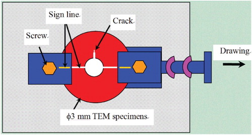
The microstructure was analyzed by TEM (JEM-2010) operating at 200 kV. The specimens for TEM observation were mechanically thinned to about 100 μm in thickness and then electrolytically thinned by the twin-jet polishing technique using a mixture of 5 vol.% perchloric acid and 95 vol.% alcohol at 20 V. Ex situ TEM tensile test was performed on a micro-strain holder as shown in . The φ3 mm TEM sample was fixed to the holder and tensile strained by drawing the movable arm carefully. The strained sample was transferred into the TEM for observation. Then, the sample was taken out from the TEM and further strained for the next observation. Similar operations were performed to investigate the microstructure evolution with an increasing strain. To repeat the stress condition at each strain, lines were scored on both the TEM specimen and holder arms to help locate the TEM specimen at the same position on the holder.
Fig. 1. Schematic illustration of the micro-strain holder.
There is nearly no dislocation in the specimen before strain as shown in (a). After the first tensile strain, a micro-crack is generated from the edge of thin area of TEM specimen ((b)). High density of dislocations ahead of the micro-crack is observed. After the second tensile strain, some stacking faults (signed as ‘S’ in (c)) nearly inclined to the crack are observed when g=[Citation002], where g is the operating reflection. Most of the stacking faults are invisible except some partial dislocations when g=[Citation022] ((d)), which indicates that the stacking faults should be instinct stacking faults.
Fig. 2. Microstructure of the TEM specimen: (a) before strain, (b) after first tensile strain, (c) after second tensile strain with g=[Citation002] and (d) after second tensile strain with g=[Citation022], insets are the corresponding SAED patterns.
![Fig. 2. Microstructure of the TEM specimen: (a) before strain, (b) after first tensile strain, (c) after second tensile strain with g=[Citation002] and (d) after second tensile strain with g=[Citation022], insets are the corresponding SAED patterns.](/cms/asset/de3ff77a-b547-42da-8e2c-03a6e850b411/tmrl_a_915433_f0002_b.gif)
The microstructure of the TEM specimen after the third tensile strain is shown in . The former stacking faults in (c) disappear. Some deformation twins (signed as ‘T’ in (a)) inclined or parallel to the crack are observed near the crack ((a)). The former stacking faults are confirmed to evolve into deformation twins by comparing the microstructure in (c) and 3(a) carefully. The deformation twins are further confirmed by the corresponding selected area electron diffraction (SAED) patterns ((b)). High-resolution TEM image shows that the twin boundary is flat and the width of the twin is only several nanometers ((c)).
Fig. 3. Microstructure of the TEM specimen after third tensile strain at (a) g=[Citation002] (deformation twins are assigned by white arrows), (b) SAED patterns and (c) high-resolution TEM image of the deformation twins corresponding to the white circle in (a).
![Fig. 3. Microstructure of the TEM specimen after third tensile strain at (a) g=[Citation002] (deformation twins are assigned by white arrows), (b) SAED patterns and (c) high-resolution TEM image of the deformation twins corresponding to the white circle in Figure 3(a).](/cms/asset/63773a11-005e-4aef-9644-a5ce65a3f3b3/tmrl_a_915433_f0003_b.gif)
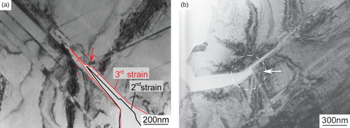
The crack in the second and third strained specimens is compared as shown in (a). The crack in the second strained specimen is rather sharp. The sharp crack expands obviously at the place where some inclined twins interact with the crack as shown by the red arrow in the third strained specimen. It seems that the inclined twins not only block the crack propagation, but also blunt the crack tip. Similar results that the crack is blunted by the inclined twins are found elsewhere ((b)).
Fig. 4. (a) Schematic illustration of the crack propagation during straining and (b) crack interaction with twins.
Although there are twins parallel to the crack at the head of crack tip ((a)), the crack tip still keeps sharp. This result suggests that the twins parallel to the crack have little effect on blocking or blunting the crack. From the investigations of low-temperature fracture of many austenitic steels with high Mn content, transgranular cracking was also observed along {111} planes and twin boundaries.[Citation16,Citation17] Those results are consistent with the observation that crack could propagate along the deformation twin boundaries without blunting in this study. Previous studies show extensive evidences that twins could serve as favorable sites for the formation of fatigue cracks.[Citation18,Citation19] Twin boundary cracks were the dominating crack events at medium amplitudes in 316 austenitic stainless steels.[Citation19,Citation20] Finite element simulations also confirmed the substantial enhancement of the driving force for the crack formation in a twinned crystal relative to a single crystal.[Citation21] Coherent twin boundaries in face centered cubic (FCC) metals are the ones with the lowest energy among all grain boundaries. In an energetic concept of material damage, such high-coincidence boundaries should be relatively stable and they are generally considered to be a strong barrier to deformation.[Citation22,Citation23] How the crack propagates along the twin boundary easily? This twin boundary crack phenomena has been well explained by Heinz and Neumann.[Citation24] They evaluated the effects of twin boundaries using anisotropic elastic models and concluded that twins induced local stress concentration, which increased the probability of nucleating a fatigue crack at a twin. It has been confirmed that the orientation of twin boundary with the crack played an important role in affecting the crack propagation. An inclined twin boundary orientation is more effective in enhancing the fracture toughness than the parallel orientation.[Citation25] The blunting of crack by the inclined twins could change the propagation way of the crack. However, once the crack turns to parallel with the former inclined twins, it could also propagate along those twin boundaries easily. Although the propagation path of crack is changed and elongated, the crack still keeps sharp along the twin boundary and the driving force for the crack propagation is not released adequately. That may be the reason why the post-uniform elongation is very short in TWIP steels. In other words, although the deformation twins improve the plasticity, they are of little help or even are harmful for the fracture once a crack had originated.
It should be pointed out that the fracture behaviors observed in the thin TEM specimens are not all the same as those in the corresponding bulk materials due to the morphology difference. However, some characterizations of the initiation and propagation of the crack should be hold both in thin specimens and bulk materials.
In conclusion, Fe–25Mn–3Si–3Al TWIP steels were ex situ tensile strained and observed using TEM to investigate the initiation and propagation of crack. Cracks initiate related to the moving of dislocations and propagate along the slip bands. Both twins parallel and inclined to the crack are produced during the crack propagation. The twins inclined to the crack notably block and blunt the crack, whereas the parallel twins exhibit no effect on the propagation of the crack.
Acknowledgements
The project is financially supported by National Natural Science Foundation of China (No. 11202183) and the National High Technology Research and Development Program (863) of China (No. 2011AA11A101). The authors are indebted to L.N. Wang (Zhejiang Sci-Tech University) for preparing the TEM specimens.
References
- Jin JE, Lee YK. Effects of Al on microstructure and tensile properties of C-bearing high Mn TWIP steel. Acta Mater. 2012;60:1680–1688. doi: 10.1016/j.actamat.2011.12.004
- Gutierrez-Urrutia I, Raabe D. Grain size effect on strain hardening in twinning-induced plasticity steels. Scripta Mater. 2012;66:992–996. doi: 10.1016/j.scriptamat.2012.01.037
- Grassel O, Kruger L, Frommeyer G, Meyer LW. High strength Fe–Mn–(Al,Si) TRIP/TWIP steels development-properties-application. Int J Plast. 2000;16:1391–1409. doi: 10.1016/S0749-6419(00)00015-2
- Zhang J, Di H, Mao K, Wang X, Han Z, Ma T. Processing maps for hot deformation of a high-Mn TWIP steel: a comparative study of various criteria based on dynamic materials model. Mater Sci Eng A. 2013;587:110–122. doi: 10.1016/j.msea.2013.08.036
- Frommeyer G, Brux U, Neumann P. Supra-ductile and high-strength manganese-TRIP/TWIP steels for high energy absorption purposes. ISIJ Int. 2003;43:438–446. doi: 10.2355/isijinternational.43.438
- Dancette S, Delannay L, Renard K, Melchior MA, Jacques PJ. Crystal plasticity modeling of texture development and hardening in TWIP steels. Acta Mater. 2012;60: 2135–2145. doi: 10.1016/j.actamat.2012.01.015
- Liu JB, Liu XH, Liu W, Zeng YW, Shu KY. Microstructure and hardness evolution during isothermal process at 700 °C for Fe–24Mn–0.7Si–1.0Al TWIP steel. Mater Charact. 2010;61:1356–1358. doi: 10.1016/j.matchar.2010.09.007
- Allain S, Chateau J-P, Dahmoun D, Bouaziz O. Modeling of mechanical twinning in a high manganese content austenitic steel. Mater Sci Eng A. 2004;387–389:272–276. doi: 10.1016/j.msea.2004.05.038
- Vercammen S, Blanpain B, Cooman BCD, Wollants P. Cold rolling behaviour of an austenitic Fe–30Mn–3Al–3Si TWIP-steel: the importance of deformation twinning. Acta Mater. 2004;52:2005–2012. doi: 10.1016/j.actamat.2003.12.040
- Shen YF, Wang YD, Liu XP, Sun X, Lin Peng R, Zhang SY, Zuo L, Liaw PK. Deformation mechanisms of a 20 Mn TWIP steel investigated by in situ neutron diffraction and TEM. Acta Mater. 2013;61:6093–6106. doi: 10.1016/j.actamat.2013.06.051
- Zhu YT, Liao XZ, Wu XL. Deformation twinning in nanocrystalline materials. Prog Mater Sci. 2012;57:1–62. doi: 10.1016/j.pmatsci.2011.05.001
- Zhu YT, Wu XL, Liao XZ, Narayan J, Kecskes LJ, Mathaudhu SN. Dislocation–twin interactions in nanocrystalline fcc metals. Acta Mater. 2011;59:812–821. doi: 10.1016/j.actamat.2010.10.028
- Saleh AA, Pereloma EV, Clausen B, Brown DW, Tomé CN, Gazder AA. On the evolution and modelling of lattice strains during the cyclic loading of TWIP steel. Acta Mater. 2013;61:5247–5262. doi: 10.1016/j.actamat.2013.05.017
- Bracke L, Mertens G, Penning J, Cooman BCD, Liebeherr M, Akdut N. Influence of phase transformations on the mechanical properties of high-strength austenitic Fe–Mn–Cr steel. Metall Mater Trans A. 2006;37:307–317. doi: 10.1007/s11661-006-0002-5
- Fabrègue D, Landron C, Bouaziz O, Maire E. Damage evolution in TWIP and standard austenitic steel by means of 3D X ray tomography. Mater Sci Eng A. 2013;579: 92–98. doi: 10.1016/j.msea.2013.05.013
- Hamada AS, Karjalainen LP, Puustinen J. Fatigue behavior of high-Mn TWIP steels. Mater Sci Eng A. 2009;517:68–77. doi: 10.1016/j.msea.2009.03.039
- Liu SC, Hashida T, Takahashi H, Kuwano H, Hamaguchi Y. A study on fractography in the low-temperature brittle fracture of an 18Cr–18Mn–0.7N austenitic steel. Metall Mater Trans A. 1998;29:791–798. doi: 10.1007/s11661-998-0270-3
- Miao J, Pollock TM, Wayne JJ. Microstructural extremes and the transition from fatigue crack initiation to small crack growth in a polycrystalline nickel-base superalloy. Acta Mater. 2012;60(6–7):2840–2854. doi: 10.1016/j.actamat.2012.01.049
- Blochwitz C, Tirschler W. Twin boundaries as crack nucleation sites. Cryst Res Tech. 2005;40(1–2):32–41. doi: 10.1002/crat.200410305
- Blochwitz C, Tirschler W. Influence of the crystalline texture on the fatigue damage. Proceedings of the Eighth International Fatigue Congress; 2002; Stockholm. Vol. 3; p. 1625–1632.
- Castelluccio GM, McDowell DL. Effect of annealing twins on crack initiation under high cycle fatigue conditions. J Mater Sci. 2013;48(6):2376–2387. doi: 10.1007/s10853-012-7021-y
- Lu K, Lu L, Suresh S. Strengthening materials by engineering coherent internal boundaries at the nanoscale. Science. 2009;324:349–352. doi: 10.1126/science.1159610
- Jin JE, Lee YK. Strain hardening behavior of a Fe–18Mn–0.6C–1.5Al TWIP steel. Mater Sci Eng A. 2009;527: 157–161. doi: 10.1016/j.msea.2009.08.028
- Heinz A, Neumann P. Crack initiation during high cycle fatigue of an austenitic steel. Acta Metall Mater. 1990;38(10):19331940. doi: 10.1016/0956-7151(90)90305-Z
- Zhou HF, Qu SX, Yang W. Toughening by nano-scaled twin boundaries in nanocrystals. Model Simul Mater Sci Eng. 2010;18:065002. doi: 10.1088/0965-0393/18/6/065002