
Abstract
Enhanced irradiation tolerance in crystalline multilayers has received significant attention lately. However, little is known on the irradiation response of crystal/amorphous nanolayers. We report on in situ Kr ion irradiation studies of a bulk Fe96Zr4 nanocomposite alloy. Irradiation resulted in amorphization of Fe2Zr and formed crystal/amorphous nanolayers. α-Fe layers exhibited drastically lower defect density and size than those in large α-Fe grains. In situ video revealed that mobile dislocation loops in α-Fe layers were confined by the crystal/amorphous interfaces and kept migrating to annihilate other defects. This study provides new insights on the design of irradiation-tolerant crystal/amorphous nanocomposites.
Next-generation nuclear energy technology requires advanced structural materials that must withstand extreme irradiation environments.[Citation1–3] One of the emerging approaches is to introduce abundant interfaces by forming nanostructures in the materials.[Citation4,Citation5] Consisting of two or more nanostructured heterophases, metallic nanolaminates exhibit not only excellent mechanical strength [Citation6–9] and fatigue resistance,[Citation10] but also impressive tolerance to ion irradiation.[Citation11–13] He ion irradiation studies have been extensively reported in immiscible nanolaminates such as Cu/V,[Citation14–16] Cu/Nb,[Citation11] Cu/W,[Citation17] Cu/Mo,[Citation18] Ag/Ni[Citation19] and Ag/V [Citation20] and miscible Al/Nb [Citation21] and Fe/W.[Citation22] Defect density and irradiation-induced hardening in these systems show a strong size dependence on individual layer thickness (h), that is the magnitude of irradiation hardening and defect density both decrease at smaller h in immiscible nanolaminates. Fu et al. first showed prominent simultaneous reduction of irradiation hardening and He bubble density in the He ion-irradiated Cu/V system when h is smaller [Citation16]; similar phenomena were later observed in several other systems, such as Ag/Ni,[Citation19] Ag/V [Citation20] and Fe/W.[Citation22] Molecular dynamics simulations [Citation23] pointed out that layer interfaces can act as effective defect sinks for irradiation-induced point defects.[Citation24] Thus, a smaller h gives rise to a greater interfacial area per unit volume, which provides more sinks to irradiation-induced point defects and clusters.
The nature of such sinks is not quite well understood to date as there are only a handful of studies on irradiation damage in nanolaminates with different types of interfaces. In general, these studies can be classified into systems with miscible and immiscible interfaces. Miscible interfaces are prone to irradiation-induced mixing and hence may be less effective to sustain irradiation damage at higher doses and temperatures.[Citation21,Citation22] In immiscible systems, several types of interfaces have been investigated, such as fcc/bcc,[Citation12,Citation14] bcc/bcc [Citation22] and fcc/fcc,[Citation19,Citation25] where fcc and bcc stand for face-centred cubic and bcc-body centred cubic, respectively. The efficiency of the immiscible interfaces to capture and annihilate point defects might be related to the density of misfit dislocations at the interfaces.[Citation12] Yu et al. recently reported in situ evidence of fast migration of defect clusters towards Ag/Ni layer interfaces decorated with high-density misfit dislocations. And the interactive energy needed to annihilate two loops with opposite nature was estimated to be ∼0.4 eV.[Citation25]
In situ irradiations inside a transmission electron microscope provide important insights for investigating dynamics of defect–defect and defect–interface interactions, thanks to real-time observation of microstructural evolution in irradiated materials. Numerous phenomena have been observed using the in situ irradiation technique, such as anisotropic void formation in Mg,[Citation26] irradiation-induced grain growth in Fe and Zr,[Citation27] defect absorption by triple junctions in nanocrystalline Ni,[Citation28] defect removal by twin boundaries (TBs) and the irradiation-induced TB migrations in nanotwinned metals,[Citation29,Citation30] and defect migration kinetics in nanoporous metals.[Citation31–33] Meanwhile several in situ mechanical testing studies on irradiated materials are also available.[Citation34,Citation35]
Most prior studies on multilayers focused on thin films (several μ m in thickness), whereas the application in nuclear reactors typically calls for bulk nanocomposites.[Citation2,Citation3,Citation5] Irradiation studies on bulk nanolaminate alloys remain scarce.[Citation36] What is more, there are no investigations on irradiation response of nanocomposites with crystal/amorphous interfaces. In this study, we report on in situ studies on the heavy ion irradiation response of a bulk FeZr nanocomposites consisting of Fe/Fe2Zr nanolaminates and submicron α-Fe grains prepared by the suction casting technique. Low-dose irradiation leads to amorphization of Fe2Zr layers and subsequent formation of Fe/amorphous Fe2Zr nanolaminates. The crystal/amorphous layer interface has extraordinary stability against irradiation and the confined migration of dislocation loops within α-Fe layers reduces their defect density significantly.
The Fe–4 at% Zr alloy was prepared by melting high-purity iron (99.95%) and zirconium (99.8%) using an Edmund Buhler AM arc melting machine. The raw materials were remelted multiple times (for homogeneity) in water-cooled Cu crucibles under an ultra high-purity (UHP) argon (Ar) atmosphere and solidified rapidly by the suction casting technique. The chamber was pumped down to a vacuum of prior to melting and later backfilled with UHP Ar at a pressure of 90 kPa during fabrication. The cooling rate of suction casting was estimated to be 1,000–
.
The as-casted alloy ingots were cylindrical rods with a diameter of 3 mm. Samples for transmission electron microscopy (TEM) study were transversely cut from the rod to avoid contamination from the crucible, followed by mechanical grinding, chemical etching and polishing. The TEM specimens were then irradiated using the intermediate voltage electron microscope (IVEM) facility at Argonne National Laboratory where a Hitachi H-9000NAR microscope was equipped with a TANDEM accelerator. TEM specimens were irradiated with 1 MeV Kr++ ions up to 2 dpa (corresponding to a dose of ) at room temperature. The beam size was ∼1.5 mm (without rastering) and was able to cover the entire thin area of TEM specimens during irradiation. A Tecnai F20 transmission electron microscope was operated at an acceleration voltage of 200 keV to examine the microstructure before and after the irradiation experiments. Scanning transmission electron microscopy (STEM) and energy-dispersive X-ray spectroscopy (EDX) analyses were conducted by using high-angle annular dark-field and Oxford detectors attached to the aforementioned TEM microscope.
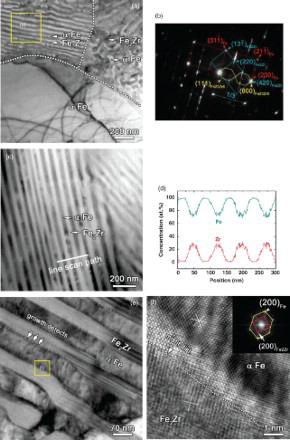
As-casted specimens contained three major components: cellular zone, nanolaminates and large α-Fe grains as shown in the TEM micrograph in (a). The volume fraction ratio of large grains to the eutectic phase is ∼2:1. The selected area diffraction (SAD) pattern of the nanolaminate in the box in (a) shows two major phases: α-Fe (examined from zone axis) and fcc-like Fe2Zr (C15 type Laves phase with Mg2Cu as prototype) along the
zone axis ((b)), consistent with X-ray diffraction profile (Figure S1). Fe23Zr6 is a minor phase as indicated by weak diffraction spots (connected by orange lines) in (b). Index of diffraction patterns suggests that α-Fe {200}//Fe23Zr6 {800}. The interplanar spacing of α-Fe {200} nearly equals that of Fe2Zr {400}, consistent with the lattice parameter ratio of the two phases (
,
),[Citation37] and the d-spacing of α-Fe {200} (0.145 nm) is similar to that of Fe23Zr6 {800} (0.15 nm,
). The streaking lines in (b) indicate the formation of high-density stacking faults that are usually observed in the Fe2Zr phase.[Citation37,Citation38] The STEM image in (c) confirms the eutectic nanolaminate structure, and its line-scan compositional profile depicted using the EDX spectrum (as shown in (d)) corresponds well with Fe2Zr and α-Fe. As Fe23Zr6 is a minority phase, we will focus on α-Fe and Fe2Zr in this irradiation study. (e) shows a magnified TEM micrograph of nanolaminates with high-density stacking faults in the Fe2Zr layers. In addition, growth defects decorating the Fe/Fe2Zr interfaces were identified. High-resolution TEM (HRTEM) micrograph of the Fe/Fe2Zr interface in (f) reveals a typical incoherent configuration of the interface, where α-Fe {200} is nearly parallel to Fe2Zr {200}, as indicated by the inset fast Fourier transformation of the image. Note that the interfacial relationship of Fe/Fe2Zr varies frequently as shown in Figure S2.
Figure 1. Microstructure and chemistry of unirradiated α -Fe/Fe2Zr nanocomposites. (a) TEM micrograph showing three typical components: large α-Fe grains, cellular and nanolaminate phases consisting of α-Fe and Fe2Zr layers. (b) The SAD pattern of nanolaminate in box b of (a) shows three sets of diffraction dots, arising from α-Fe, Fe2Zr and Fe23Zr6, respectively (see Supplementary Figure S1 and S2 for more detail), observed from ⟨ 110⟩ zone axes of bcc α-Fe and fcc-like Fe23Zr6, and ⟨ 112⟩ zone axis of fcc-like Fe2Zr. The streaking lines indicate the formation of high-density stacking faults in the Fe2Zr phase. (c) STEM image reveals the laminar α-Fe and Fe2Zr with an average layer thickness of ∼50 nm. (d) The alternating compositional line profile of nanolaminate determined by EDX spectrum corresponds to α-Fe and Fe2Zr. (e) Magnified TEM micrograph shows stacking faults in Fe2Zr layers and growth defects decorating the Fe/Fe2Zr layer interfaces. (f) HRTEM micrograph reveals incoherent atomic configuration along the Fe/Fe2Zr layer interface.
In situ irradiation experiments were performed using 1 MeV Kr ions up to a dose of two displacements-per-atom (dpa). TEM micrograph of the Kr ion-irradiated specimen at 1 dpa ((a)) shows abundant defect clusters in large Fe grains. In contrast, much fewer defects were generated in the cellular zones. Irradiated nanolaminates at 1 dpa ((b)) have exceptionally low defect density, despite the sporadically visible dislocation loops bounded in the Fe layers. A magnified TEM image ((c)) of nanolaminates shows defective Fe and clean Fe2Zr layers. Moreover, the inserted SAD pattern shows a diffuse ring indicating the amorphization of Fe2Zr. An HRTEM micrograph in (d) shows significant amorphization of Fe2Zr adjacent to interfaces in nanolaminates (see Supplementary Figure S3 for more details).
Figure 2. Microstructure evolution of α−Fe/Fe2Zr nanocomposites subjected to in situ Kr ion irradiation up to two displacements-per-atom (dpa). (a) At 1 dpa, TEM micrograph showing abundant defect clusters in the large α-Fe grains. In contrast, smaller defect clusters were observed in cellular areas, residing at the phase boundaries and remained stable during successive irradiation experiments. (b) α-Fe layers in irradiated nanolaminates were mostly clean, with sporadic dislocation loops. Little defect clusters were detected in the irradiated Fe2Zr layers. (c) At 2 dpa, a TEM micrograph of irradiated nanolaminate shows the retention of sharp layer interfaces between α-Fe and Fe2Zr. The halo ring in the inserted SAD pattern reveals the formation of amorphous Fe2Zr. (d) An HRTEM micrograph along the interface showing amorphization of Fe2Zr in irradiated nanolaminates. α-Fe remained a crystalline structure. Comparison of dose-dependent evolution of defect clusters in α-Fe in large grains and nanolaminates. (e) Defect density in α-Fe large grains increased rapidly during the initial irradiation, and appeared to reach saturation by ∼1.25 dpa. In comparison, defect density in α-Fe in nanolaminate was nearly an order of magnitude lower and barely changed up to 2 dpa. (f) In large α-Fe grains, defect size increased monotonically with dose to ∼60 nm up to 2 dpa, in drastic contrast to nearly unchanged defect dimension of ∼20 nm in the α -Fe layers in nanolaminates.
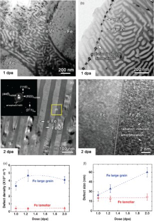
Statistical studies (in (e)) show that defect density in large Fe grains increased rapidly during the initial stage of irradiation, and appeared to reach saturation by , whereas defect density in Fe layers within nanolaminates was much lower and barely varied up to 2 dpa. Meanwhile in large Fe grains, defect size increased monotonically with dose to ∼60 nm at 2 dpa ((f)), in drastic contrast to nearly unchanged defect dimension of ∼20 nm in Fe layers in nanolaminate (Figure S4). As defect clusters were absent in irradiated Fe2Zr layers in nanolaminates, no statistical data were available for comparison for Fe2Zr layers.
The saturated defect density in the Fe layers of Fe/Fe2Zr nanolaminates is much lower than that in large Fe grains, implying that a large number of defects must have been annihilated during irradiation. In order to examine the evolution of microstructure of irradiated nanolaminates, we will show two important phenomena captured during in situ irradiation studies. The first one is low dose irradiation- (less than 0.1 dpa) induced amorphization of Fe2Zr and subsequent formation of crystal/amorphous interfaces and the second case is a higher dose irradiation initiated dislocation loop migration in Fe layers.
Low-dose irradiation-induced amorphization of Fe2Zr and the formation of crystal/amorphous interfaces in Fe/Fe2 Zr nanolaminates. (a) shows a series of snapshots of numerous events of dislocation absorption by the Fe/Fe2Zr layer interface at a low dose () (Supplementary Video 1). Before irradiation, crystalline Fe2Zr layers contained high-density stacking faults. At 1 s, a dislocation formed in the Fe layer A and started to evolve and migrate towards the right layer interface, as indicated by a small arrow. At 1.1 s, the evolving dislocation became longer and well defined, and nearly reached layer interface. Meanwhile another dislocation line emerged in the Fe layer B. The two dislocations continued to migrate rightwards at 1.3 s and the dislocation in layer A was completely absorbed by layer interfaces at 1.4 s, followed by absorption of the dislocation in layer B. Furthermore, the crystalline Fe2Zr layers became amorphous.
Figure 3. Defect annihilation by layer interface and amorphization of the Fe2Zr phase in nanolaminates. (a)In situ snapshots of dislocation absorption by the Fe/Fe2Zr layer interface at a dose of about 0.01 dpa (over less than 2 s). At 1 s, a dislocation formed in the α-Fe layer A and started to evolve and migrate towards the right layer interface, as indicated by the small arrow. The dotted lines mark the ends of the dislocation lines and the small arrows indicate the migration direction. At 1.1 s, the dislocation in layer A became longer and another dislocation line was formed in Fe layer B. The two dislocations continued to migrate rightwards at 1.2 and 1.3 s and were absorbed by layer interface at 1.4 s. By 0.2 dpa, Fe2Zr became nearly amorphous. See Figure S5, Supplementary Videos 1 and 2 for more details. (b) Schematics of the ‘interface-assisted annihilation’ mechanism demonstrating the absorption of dislocations by layer interfaces and amorphization of Fe2Zr at low irradiation dose.
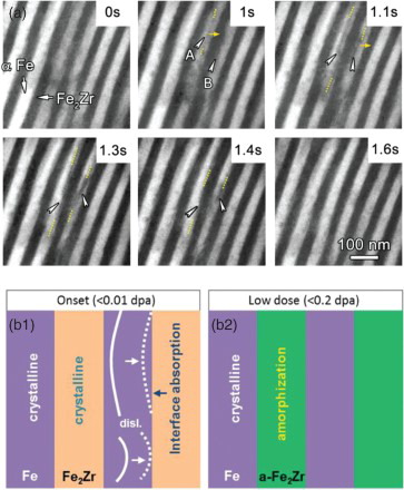
Schematics in (b) illustrate the ‘interface-assisted annihilation’ of dislocations and subsequent amorphization of Fe2Zr. First, irradiation-induced dislocation loops in Fe layers evolve into dislocation lines, which propagate towards the Fe/Fe2Zr layer interfaces ((b1)). The absorption of dislocations then leads to the distortion of the crystalline structure in Fe2Zr layers. Due to the defect absorption and quenching of cascades, amorphization occurs in Fe2Zr layers ((b2)). Note that irradiation caused immediate destruction of stacking faults in the Fe2Zr layers, followed by their amorphization at very low doses (<0.2 dpa). Meanwhile, the layer interface remained stable (chemically abrupt) during the entire irradiation experiments (at higher dose). Post-irradiation analysis also evidenced amorphization () and the absence of stacking faults throughout the irradiated specimen. Another example of low-dose irradiation-induced defect evolution is shown in Figure S5 and Supplementary Video 2. It is well known that irradiation breaks chemical bonds of compounds, such as Fe2Zr in this study, and induces their amorphization. On the other hand, it is likely that the layer interface actively absorbed interstitials or interstitial clusters, creating rapid disordering in the irradiated Fe2Zr layer. The layered Fe2Zr might experience accelerated radiation-induced amorphization in comparison with the bulk counterpart. Thus, the reason for the amorphization of Fe2Zr was a combination of defect kinetics and disordering of the chemical bonds induced by heavy ion bombardment.
High-dose irradiation-induced migration of dislocation loops in Fe layers in nanolaminates (up to 2 dpa). We observed different types of defect morphology in various zones of irradiated specimens. First, in α-Fe grains, discrete dislocation loops were frequently observed. Many individual loops also combine with one another to form dislocation segments at greater doses. Second, in the cellular zone, defect clusters were often bounded by layer interfaces ((a)). Third, Fe2Zr nanolayers in nanolaminates were frequently depleted with defect clusters, while defect clusters are typically sporadically distributed in α-Fe layers. And the amorphization of Fe2Zr nanolayers is widespread in nanolaminates.
Numerous mechanisms could contribute to the drastic reduction of defect cluster density in Fe nanolayers. Misfit dislocations at layer interfaces ((e)–(f)) may play a role in removing defects. Excess free volume at misfit dislocations can act as sinks to point defects. This mechanism has been proposed to explain size-dependent reduction of defect density in Kr ion-irradiated Ag/Ni,[Citation25] and He-irradiated Cu/Nb,[Citation12] Cu/V [Citation16] and Fe/W [Citation22] multilayers. However, unlike the previously observed rapid migration of defect clusters towards layer interface in the Ag/Ni system, we observed, through in situ studies, an interesting unexplored mechanism through which defect clusters were removed in -Fe nanolayers (channels) in nanolaminates with crystal/amorphous layer interfaces.
In situ TEM snap shots in (a) capture one such typical defect annihilation process in Fe nanolayers in nanolaminates. A dislocation loop A (outlined in circle in (a)) nucleated at 0.755 dpa and started to migrate (Supplementary Video 3). Loop A migrated continuously during subsequent irradiation, while another dislocation loop B emerged at 0.849 dpa. Loop A migrated over a distance of 295 nm before it encountered loop B at 0.885 dpa. Subsequently, the two loops interacted and annihilated each other at 0.907 dpa.
Figure 4. Annihilation of defect clusters via mobile dislocation loops in confined layers. (a) In situ TEM snapshots of dislocation loop migration over a dose range of 0.737–0.907 dpa (over 70 s) in confined nanolaminates. At 0.755 dpa, a dislocation loop A was generated and started to migrate downwards within the α-Fe layer, as outlined by the circle. Loop A migrated over a distance of 295 nm by 0.885 dpa before it encountered loop B. The two loops then interacted and combined with each other at 0.885 dpa and eventually disappeared at 0.907 dpa. More details are shown in Supplementary Videos 3 and 4. (b) Schematics of the defect removal mechanism illustrating the migration of dislocation loops in α-Fe channels and the recombination of dislocation loops with opposite nature. Notice that α-Fe layers are sandwiched between amorphous Fe2Zr layers.
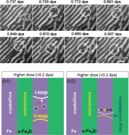
The mechanism of such defect annihilation is shown schematically in (b). First, defect clusters in Fe layers can evolve into a larger dislocation loop confined by crystal/amorphous layer interfaces. Mobile dislocation loops can migrate over hundreds of nanometres in long narrow α-Fe layers (channels), wherein point defects of the same (opposite) nature are collected (removed) ((b1)). Meanwhile such mobile interstitial loops may eventually encounter and annihilate vacancy loops in the channel ((b2)). Thus, these mobile interstitial loops could act as the ‘sweeper’ in the Fe layer to wipe out most other immobile defect clusters before they are annihilated by loops with the opposite Burgers vector. In contrast in large α-Fe grains, the dimension and density of defect clusters increase monotonically with dose as there is insufficient defect sinks to absorb these defects. In the cellular zones, the defects are bounded by limited layer interfaces with insufficient capability (or low probability) to nucleate mobile dislocation loops.
The role of amorphous Fe2Zr nanolayers is critical. First, the amorphous layers have abundant excess free volume, which can accommodate a large number of irradiation-induced point defects in α-Fe. Second, such amorphous layers are not transparent to mobile dislocation loops. The mobile dislocation loops generated in confined α-Fe channels can thus propagate frequently to collect and remove other types of irradiation-induced defect clusters. Third, the crystal/amorphous interface is resistant to irradiation-induced intermixing up to at least 2 dpa, even though the adjacent layers include identical elements (Fe). Fourth, the amorphous Fe2Zr interface curtails the growth of defect clusters in irradiated Fe layers.
In summary, rapidly solidified bulk Fe96Zr4 nanocomposite consists of Fe/Fe2Zr nanolaminates, cellular zones and large Fe grains. Irradiated nanolaminates contained much lower defect density and smaller defect size than those in large Fe grains. Low-dose irradiation-induced amorphization of Fe2Zr and the crystal/amorphous layer interfaces absorbed irradiation-induced defects and led to confinement of defect clusters. In situ video evidenced active defect annihilation due to the sweeping effect of mobile dislocation loops confined in Fe nanolayers. This study provides an encouraging outlook on the implementation of crystal/amorphous interfaces in the design of bulk irradiation-tolerant nanocomposites for extreme irradiation environments.
Supplementary online material
More detailed information on experiments is available at http://dx.doi.org/10.1080/21663831.2014.941494.
Supplementary material
Download Zip (46.4 MB)Acknowledgements
We acknowledge financial support by NSF-DMR-Metallic Materials and Nanostructures Program under grant no. 1304101. ZF and YL are supported financially by NSF-CMMI 1161978. K.Y. Yu acknowledges financial support by Science Foundation of China University of Petroleum, Beijing (no. 2462014 YJRC019). XZ and HW also acknowledge Strategic research fund for new research initiatives provided by College of Engineering, Texas A&M University. We also thank Peter M. Baldo and Edward A. Ryan at Argonne National Laboratory for their help during in situ irradiation experiments. The IVEM facility at Argonne National Laboratory is supported by DOE-BES. Access to the DOE—Center for Integrated Nanotechnologies (CINT) at Los Alamos and Sandia National Laboratories and Microscopy and Imaging Center at Texas A&M University is also acknowledged.
References
- Grimes RW, Konings RJ, Edwards L. Greater tolerance for nuclear materials. Nat Mater. 2008;7:683–685.
- Zinkle SJ, Busby JT. Structural materials for fission and fusion energy. Mater Today. 2009;12:12–19. doi: 10.1016/S1369-7021(09)70294-9
- Zinkle SJ, Was GS. Materials challenges in nuclear energy. Acta Materialia. 2013;61:735–758. doi: 10.1016/j.actamat.2012.11.004
- Sickafus KE, Grimes RW, Valdez JA, Cleave A, Tang M, Ishimaru M, Corish SM, Stanek CR, Uberuaga BP. Radiation-induced amorphization resistance and radiation tolerance in structurally related oxides. Nat Mater. 2007;6:217–223.
- Odette GR, Alinger MJ, Wirth BD. Recent Developments in Irradiation-Resistant Steels. Annu Rev Mater Res. 2008;38:471–503. doi: 10.1146/annurev.matsci.38.060407.130315
- Misra A, Verdier M, Lu YC, Kung H, Mitchell TE, Nastasi M, Embury JD. Structure and mechanical properties of Cu-X (X = Nb,Cr,Ni) nanolayered composites. Scripta Mater. 1998;39:555–560. doi: 10.1016/S1359-6462(98)00196-1
- Anderson P, Li C. Hall-Petch relations for multilayered materials. Nanostruct Mater. 1995;5:349–362. doi: 10.1016/0965-9773(95)00250-I
- Hoagland R, Mitchell T, Hirth J, Kung H. On the strengthening effects of interfaces in multilayer fee metallic composites. Philos Mag A. 2002;82:643–664.
- Zhang X, Misra A, Wang H, Shen T, Nastasi M, Mitchell T, Hirth J, Hoagland R, Embury J. Enhanced hardening in Cu/330 stainless steel multilayers by nanoscale twinning. Acta Mater. 2004;52:995–1002. doi: 10.1016/j.actamat.2003.10.033
- Zhang JY, Liu Y, Chen J, Chen Y, Liu G, Zhang X, Sun J. Mechanical properties of crystalline Cu/Zr and crystal–amorphous Cu/Cu–Zr multilayers. Mater Sci Eng A. 2012;552:392–398. doi: 10.1016/j.msea.2012.05.056
- Zhang X, Li N, Anderoglu O, Wang H, Swadener JG, Höchbauer T, Misra A, Hoagland RG. Nanostructured Cu/Nb multilayers subjected to helium ion-irradiation. Nucl. Instrum. Methods Phys. Res. B, Beam Interact. Mater. At. 2007;261:1129–1132.
- Zhang X, Fu E, Li N, Misra A, Wang Y-Q, Shao L, Wang H. Design of Radiation Tolerant Nanostructured Metallic Multilayers. J Eng Mater Technol. 2012;134:041010. doi: 10.1115/1.4006979
- Misra A, Demkowicz M, Zhang X, Hoagland R. The radiation damage tolerance of ultra-high strength nanolayered composites. JOM J Miner Metal Mater Soc. 2007;59: 62–65. doi: 10.1007/s11837-007-0120-6
- Fu EG, Misra A, Wang H, Shao L, Zhang X. Interface enabled defects reduction in helium ion irradiated Cu/V nanolayers. J Nucl Mater. 2010;407:178–188. doi: 10.1016/j.jnucmat.2010.10.011
- Fu EG, Wang H, Carter J, Shao L, Wang YQ, Zhang X. Fluence-dependent radiation damage in helium (He) ion-irradiated Cu/V multilayers. Philos Mag. 2012;93: 883–898. doi: 10.1080/14786435.2012.735773
- Fu EG, Carter J, Swadener G, Misra A, Shao L, Wang H, Zhang X. Size dependent enhancement of helium ion irradiation tolerance in sputtered Cu/V nanolaminates. J Nucl Mater. 2009;385:629–632. doi: 10.1016/j.jnucmat.2008.12.308
- Yuan W. Helium effect on the stability of the interface of Cu/W nanomultilayer. Acta Phys Sin. 2012;61: Article no. 176802. Available from http://wulixb.iphy.ac.cn/EN/abstract/abstract50594.shtml
- Li N, Carter JJ, Misra A, Shao L, Wang H, Zhang X. The influence of interfaces on the formation of bubbles in He-ion-irradiated Cu/Mo nanolayers. Philos Mag Lett. 2010;91:18–28. doi: 10.1080/09500839.2010.522210
- Yu KY, Liu Y, Fu EG, Wang YQ, Myers MT, Wang H, Shao L, Zhang X. Comparisons of radiation damage in He ion and proton irradiated immiscible Ag/Ni nanolayers. J Nucl Mater. 2013;440:310–318. doi: 10.1016/j.jnucmat.2013.04.069
- Wei QM, Li N, Mara N, Nastasi M, Misra A. Suppression of irradiation hardening in nanoscale V/Ag multilayers. Acta Mater. 2011;59:6331–6340. doi: 10.1016/j.actamat.2011.06.043
- Li N, Martin MS, Anderoglu O, Misra A, Shao L, Wang H, Zhang X. He ion irradiation damage in Al/Nb multilayers. J Appl Phys. 2009;105:123522–123528. doi: 10.1063/1.3138804
- Li N, Fu EG, Wang H, Carter JJ, Shao L, Maloy SA, Misra A, Zhang X. He ion irradiation damage in Fe/W nanolayer films. J Nucl Mater. 2009;389:233–238. doi: 10.1016/j.jnucmat.2009.02.007
- Demkowicz MJ, Bellon P, Wirth BD. Atomic-scale design of radiation-tolerant nanocomposites. MRS Bulletin. 2010;35:992–998. doi: 10.1557/mrs2010.704
- Zhang X, Fu EG, Misra A, Demkowicz MJ. Interface-enabled defect reduction in He ion irradiated metallic multilayers. JOM. 2010;62:75–78. doi: 10.1007/s11837-010-0185-5
- Yu KY, Sun C, Chen Y, Liu Y, Wang H, Kirk MA, Li M, Zhang X. Superior tolerance of Ag/Ni multilayers against Kr ion irradiation: an in situ study. Philos Mag. 2013;93:3547–3562. doi: 10.1080/14786435.2013.815378
- Xu W, Zhang Y, Cheng G, Jian W, Millett PC, Koch CC, Mathaudhu SN, Zhu Y. In-situ atomic-scale observation of irradiation-induced void formation. Nat Commun. 2013;4:2288.
- Kaoumi D, Motta AT, Birtcher RC. A thermal spike model of grain growth under irradiation. J Appl Phys. 2008;104:073525. doi: 10.1063/1.2988142
- Sun C, Song M, Yu K, Chen Y, Kirk M, Li M, Wang H, Zhang X. In situ Evidence of Defect Cluster Absorption by Grain Boundaries in Kr Ion Irradiated Nanocrystalline Ni. Metall Mater Trans A. 2013;43:1966–1974.
- Yu KY, Bufford D, Sun C, Liu Y, Wang H, Kirk MA, Li M, Zhang X. Removal of stacking-fault tetrahedra by twin boundaries in nanotwinned metals. Nat Commun. 2013;4:1377. doi: 10.1038/ncomms2382
- Yu KY, Bufford D, Khatkhatay F, Wang H, Kirk MA, Zhang X. In situ studies of irradiation-induced twin boundary migration in nanotwinned Ag. Scripta Materialia. 2013;69:385–388. doi: 10.1016/j.scriptamat.2013.05.024
- Sun C, Bufford D, Chen Y, Kirk M, Wang Y, Li M, Wang H, Maloy S, Zhang X. In situ study of defect migration kinetics in nanoporous Ag with enhanced radiation tolerance. Sci Rep 3737. 2014;4: Article no. 3737.
- Fu EG, Caro M, Zepeda-Ruiz LA, Wang YQ, Baldwin K, Bringa E, Nastasi M, Caro A. Surface effects on the radiation response of nanoporous Au foams. Appl Phys Lett. 2012;101:191607. doi: 10.1063/1.4764528
- Bringa EM, Monk JD, Caro A, Misra A, Zepeda-Ruiz L, Duchaineau M, Abraham F, Nastasi M, Picraux ST, Wang YQ, Farkas D. Are Nanoporous Materials Radiation Resistant? Nano Lett. 2011;12:3351–3355.
- Kiener D, Hosemann P, Maloy S, Minor A. In situ nanocompression testing of irradiated copper. Nat mater. 2011;10:608–613.
- Landau P, Guo Q, Hattar K, Greer JR. The Effect of He Implantation on the Tensile Properties and Microstructure of Cu/Fe Nano-Bicrystals. Adv Graph Mag. 2013;23:1281–1288.
- Han W, Demkowicz MJ, Mara NA, Fu E, Sinha S, Rollett AD, Wang Y, Carpenter JS, Beyerlein IJ, Misra A. Design of Radiation Tolerant Materials Via Interface Engineering. Adva Mater. 2013;25:6975–6979. doi: 10.1002/adma.201303400
- Stein F, Sauthoff G, Palm M. Experimental determination of intermetallic phases, phase equilibria, and invariant reaction temperatures in the Fe-Zr system. J Phase Equilib Diffus. 2002;23:480–494. doi: 10.1361/105497102770331172
- Liu Y, Livingston JD, Allen SM. Room-temperature deformation and stress-induced phase. Metall Mater Trans A. 1992;23:3303–3308.