
 ?Mathematical formulae have been encoded as MathML and are displayed in this HTML version using MathJax in order to improve their display. Uncheck the box to turn MathJax off. This feature requires Javascript. Click on a formula to zoom.
ABSTRACT
An interstitial solute strengthened high entropy alloy (iHEA), Fe49.5Mn30Co10Cr10C0.5 (at.%), was successfully additively manufactured via selective laser melting. The as-built iHEA exhibits a hierarchically heterogeneous microstructure with length scales across several orders of magnitude, which engenders an enhanced strength–ductility combination relative to those fabricated by conventional processing routes. The high yield strength mainly stemmed from the dislocation strengthening besides the friction stress and grain boundary strengthening. The joint activation of multiple deformation mechanisms involving dislocation slip, deformation twinning and phase transformation can maintain the steady work-hardening behavior at high stress levels, leading to a high ductility.
GRAPHICAL ABSTRACT
IMPACT STATEMENT
A hierarchical interstitial high entropy alloy, Fe49.5Mn30Co10Cr10C0.5 (at.%), was successfully additively manufactured via selective laser melting. Its exceptional strength–ductility synergy surpasses that of the most SLM processed conventional alloys.
1. Introduction
High entropy alloys (HEAs) have attracted extensive investigations due to their scientific significance and application prospects [Citation1]. Recently, novel mechanism-driven HEAs have been designed by incorporating other strengthening and deformation mechanisms besides the inherent solid solution strengthening, such as precipitation strengthening [Citation2,Citation3], interstitial solid solution strengthening [Citation4–6], twinning- or/and transformation-induced plasticity (TWIP and TRIP, respectively) [Citation7–11], to push the property boundary of possibility. Of these strategies, introducing the small-sized atoms, such as carbon, boron and oxygen, to develop the interstitial solute strengthened HEAs (iHEAs) is attractive to manipulate the mechanical properties [Citation4–6]. For instance, a carbon-doped iHEA, Fe49.5Mn30Co10Cr10C0.5 (at.%), could jointly activate the TWIP and TRIP mechanisms to harvest an enhanced strength–ductility combination relative to the interstitial-free reference alloy [Citation5,Citation8,Citation10,Citation12]. However, leaving aside the production of structural components with sophisticated geometry, the precise controlling of metallurgy and subsequent thermomechanical treatments based on the conventional fabrication methods causes significant inefficiency in term of cost and productivity [Citation13]. With respect to the applications of this novel alloy, it is crucial to develop advanced manufacturing technologies in an integrated manner while maintaining comparable properties.
Selective laser melting (SLM) could construct near-net shape components through a layer-by-layer method with design freedom [Citation13]. During SLM, the highly localized melting/solidification enables the formation of a hierarchically metastable microstructure that is not accessible through the conventional metallurgical methods, engendering excellent mechanical properties [Citation14,Citation15]. However, as one of most versatile additive manufacturing technologies, the application of SLM to prepare HEAs is still limited [Citation16–18]. Herein, we employed SLM to fabricate the carbon-doped iHEA to investigate its printability, microstructures, tensile properties and deformation mechanisms. The results of present investigations are important both scientifically, for bridging the microstructure-property relationship of SLM processed alloys, and technologically, for guiding the structural design of HEAs.
2. Materials and methods
The characteristics of the gas-atomized iHEA powders can be found in the Table S1 and Figure in the Supplementary information (SI). The samples were fabricated in the argon atmosphere using a ProX 300 machine based on the optimal printing parameters: laser power = 180 W, layer thickness = 40 µm, hatching space = 55 µm, and scanning speed = 1000 mm/s. The scanning strategy, building direction and scanning direction are shown in Figure S2(a). The tensile specimens with a gauge dimension of 10 mm × 2.5 mm × 1.2 mm were machined from the block samples, as illustrated in Figure S2(b). Tensile tests were performed with a strain rate of 10−3/s on a universal Instron-5982 testing machine.
The chemical composition of the powder and as-built samples was listed in Table S2, indicating that their overall chemical composition is near to the nominal composition with impurity elements of Al and Ni. The porosity level was measured through area percentage measurements using an optical microscope (OM), as exhibited in Figure S2(c,d), validating the fabrication of near fully dense samples with porosity level less than 1%. The microstructures of the samples were characterized using X-ray diffraction (XRD), scanning electron microscopy (SEM), electron backscattered diffraction (EBSD), transmission electron microscopy (TEM) and scanning TEM (STEM). For the EBSD grain boundary (GB) maps, the 15° criterion was used to distinguish the low angle GBs (LAGBs) and high angle GBs (HAGBs). TEM observations were carried out on a JEOL 2200F with a field mission gun operating at 200 kV.
3. Results and discussion
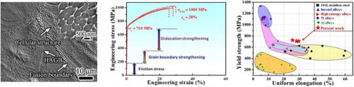
Figure indicates that the as-built iHEA possesses a hierarchically heterogeneous microstructure with length scales across several orders of magnitude. The semi-elliptical fusion boundaries are visible while the estimated height and width of the melt pools were 55.3 ± 9.5 µm and 95.1 ± 8.5 µm, respectively (Figure (a)). The HAGBs and cellular structures are readily traced in the SEM image (Figure (b)) and the average size (λ) of the cellular structures with either equiaxed or columnar morphology is measure to be 0.63 ± 0.23 µm (Figure ). The STEM morphology (Figure (c)) reveals the cell walls with average spacing of about 0.4 µm are decorated with a high density of dislocations with relatively clean interiors. The inset high-resolution TEM (HRTEM) image indicates the lattice constant of as-built iHEA can be derived to be about 3.7 Å. All elements among the cells are uniformly distributed without apparent segregation (Figure (h)). No carbides, as observed in the SLM processed carbon-doped CoCrFeNiMn [Citation17], could be detected. Instead, a few Al-rich oxides formed along cellular boundaries due to the oxidation of Al impurity (Figure ).
Figure 1. (a) OM images of the as-built iHEA. (b) SE image obtained from the area in (a). The inset shows the equiaxed cellular structures. (c) STEM image of the equiaxed cellular structures and the inset HRTEM image showing the distance across 5 {111} planes. (d) IPF map and (e) phase map superimposed with the GB map. (f,g) IPF (the dashed lines show the fusion boundaries) and KAM maps. (h) STEM-EDS maps of the cellular structures.
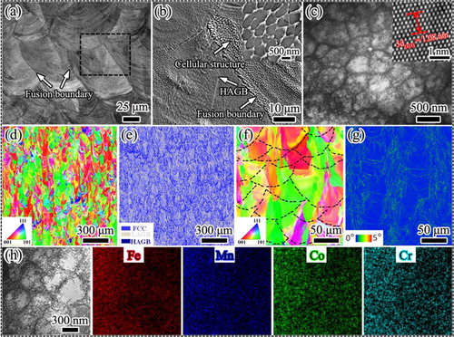
The grain orientation, phase and GBs information were measured by EBSD (Figure (d–g)). The inverse pole figure (IPF) map along the building direction in Figure (d) shows that columnar grains grew mainly along the directions of <001> and <101>. In contrast to the dual phases, viz. the face-centered cubic (FCC) γ phase and the hexagonal close-packed (HCP) ε phase, formed in this iHEA prepared by conventional methods [Citation5], the phase map superimposed with the GB map (Figure (e)) validates the formation of the single FCC phase, which is also substantiated by the XRD results (Figure ). The thermally induced martensitic transformation could be kinetically inhibited due to the fast cooling rate during SLM. The as-built iHEA contains a high fraction of LAGBs (about 59%) without twin boundaries (TBs). The approximate average grain size (d) based on the HAGBs is ∼10 µm. The IPF map (Figure (f)) can substantiate the formation of columnar grains through the epitaxial growth mode across the fusion boundaries. The kernel average misorientation (KAM) map (Figure (h)) illustrates the local misorientation on the order of 0.2°–0.9° across individual grain.
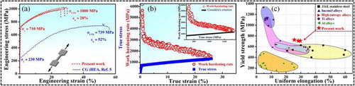
The representative tensile engineering stress–strain curves of the iHEA and coarse-grained (CG) iHEA were shown in Figure (a). The as-built iHEA exhibited a high yield strength (σy) and ultimate tensile strength (σUTS) of ∼710 MPa and 1 GPa, respectively, which are much higher than those (∼230 MPa and ∼720 MPa) of the CG iHEA [Citation5]. Also, it maintains a high uniform elongation (εu) of ∼28%. Thus, the as-built iHEA possesses a comparable strength–ductility synergy to that of high-performance iHEAs achieved through special hierarchical microstructure design [Citation12]. Figure (b) presents the true stress–strain curves superimposed with the corresponding work-hardening rate versus true strain of the as-built iHEA. The inset of Figure (b) illustrates a pronounced work-hardening ability at high stress levels, leading to a high ductility. Particularly, a direct comparison of the σy and εu with those of SLM processed conventional alloys, such as Ti alloys and stainless steels, whose mechanical data are shown in the Table S3, indicates its superior status in the strength–ductility synergy, as illustrated in Figure (c). Therefore, the extraordinary mechanical properties were achieved in the iHEA through the integrated SLM process without any post-treatment.
Figure 2. (a) Engineering stress–strain curves of the as-built iHEA compared to the CG iHEA with grain size of ∼160 µm. (b) True stress–strain and work-hardening rate–true strain curves. The inset shows the work-hardening rate–true stress curve and the Considère’s criterion for necking. (c) A summary of the σy versus εu for various SLM processed alloys.
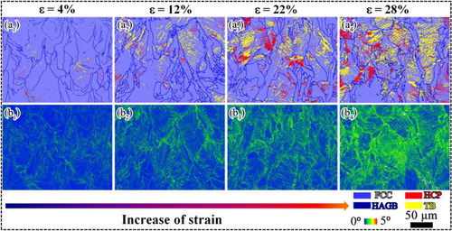
To understand the origin of the excellent properties, the microstructural evolution during deformation was characterized by EBSD (Figure ). At an early deformation with a strain of 4% (Figure (a1)), a minor volume fraction (∼0.7%) of deformation-induced HCP phase with a lath shape was detected within the FCC matrix. Also, a few twins formed inside the FCC matrix, implying that deformation twinning was activated to accommodate the plasticity. When the strain reached 12% and 22% (Figure (a2,a3)), the fractions of HCP phase increased to ∼1.9% and 6.3%, respectively, while twins fraction increased to 6.3% and 7.1%, respectively. The lath HCP phase tended to thicken and grew toward each other, bringing in the formation of large blocks of HCP phase. After fracture with εu of 28% (Figure (a4)), the fraction of the HCP phase and twins further increased to 9.5% and 7.4%, respectively. The phase transformation from FCC to HCP during deformation was supported by the XRD in Figure . Besides, the KAM values (Figure (b1–b4)) increased apparently with the strain, suggesting an increasing density of geometrically necessary dislocations [Citation19].
Figure 3. (a1–a4) EBSD phase and GBs maps showing microstructural evolution at different strain levels. (b1–b4) Corresponding KAM maps of the FCC and HCP grains.
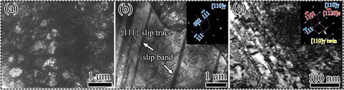
The postmortem microstructure at different strain levels were investigated by TEM for understanding the steady work-hardening capability. Figure (a–c) present the microstructures after initial deformation (ε = 4%). It is clear that the high density of dislocations were trapped and accommodated within many cellular structures (Figure (a)). Additionally, planar slip bands with width of several hundred nanometers formed in some areas to carry the deformation (Figure (b)). Moreover, deformation twins and phase transformation can be occasionally observed (Figure (c)). Based on the inset selected area electron diffraction (SAED) pattern, besides the diffraction spots from the deformation twins, the weak diffraction streak pointed by an arrow provided strong evidence of the formation of the HCP phase. These HCP structures resided within the nanotwins, forming a nanotwin-HCP lamella composite structure [Citation20].
Figure 4. Deformation structures of the iHEA after 4% strain. The insets in (b) and (c) show the SAED pattern.
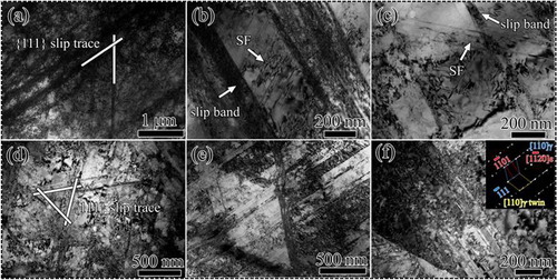
When the strain increased to 12%, a higher density of slip bands with a reduction of mean spacing transected the cell structures and the second slip system was activated (Figure (a)). In addition, profuse stacking faults (SFs) formed between slip bands (Figure (b)) and these SFs could be intersected by the slip bands (Figure (c)), both of which are beneficial for the work-hardening behavior [Citation21]. Also, the amount of the nanotwin-HCP structure apparently increased, which was not shown here. After fracture with a εu ∼28%, the complex three-dimensional networks based on the interactions among slip bands of different slip systems (Figure (d)) as well as the interaction between slip bands and nanotwin-HCP structures (Figure (e)) were clearly visible in several regions. More significantly, the nanotwin-HCP structure was detected frequently and the amount of the HCP phase increased remarkably (Figure (f)). The detailed orientation relationship and atomic structures of FCC and HCP phases can be found in Figure S6. Generally, with the plastic strain, along with the dislocation activities, deformation twinning and phase transformation play increasingly essential roles in accommodating the plasticity to maintain the steady work-hardening ability at high stress levels.
Figure 5. Deformation structures of the iHEA after 12% strain (a–c) and fracture (d–f). The inset in (f) shows the SAED pattern.
It is known that the rapid melting/solidification during SLM leads to steep temperature gradients and large thermal stresses, enabling a hierarchically heterogeneous microstructure that cannot be readily achieved in materials fabricated by conventional methods [Citation15]. For the present as-built iHEA, its σy was about three times higher than that of the cast counterparts, which originated from various strengthening contributors in terms of lattice friction stress (σA), GB strengthening (σGB), and dislocation strengthening (σρ), which can be expressed as
An early study estimated the σA of 179 MPa [Citation12]. The σGB can be described by the Hall-Petch relationship,
, where ky is the GB strengthening coefficient, 573 MPa×m m1/2 [Citation12]. According to the previous study [Citation15], assuming that this strengthening effect scales with the cell size (∼0.63 µm and 0.4 µm obtained by SEM and TEM, respectively), the estimated σGB is 721 and 906 MPa, both of which are higher than the experimental σy (∼710 MPa). Therefore, the cellular boundary herein is not as effective as the HAGBs in term of strengthening. Instead, the σGB stemmed from the HAGBs and was about 181 MPa (the average d of ∼10.0 µm).
It was revealed that the cellular structures can contribute to σy through the dislocation strengthening [Citation18] based on the expression of , where M is the Taylor factor (3.06), α is a constant (0.2), G is the shear modulus (76 GPa), b is the magnitude of Burgers vector (0.262 nm), and ρ is the dislocation density, which was roughly 7.36 × 10¹⁴ m−2 based on the XRD measurement, as shown in the SI [Citation22,Citation23]. Thus, the contribution of σρ is estimated to be 325 MPa. Combined with the σA, σGB and σρ, the calculated σy of 685 MPa was in agreement with the experimental values. The internal stress induced during SLM can make a minor contribution to the σy, while the strengthening effect of few oxides is negligibly small [Citation15,Citation24]. On the whole, although the lattice friction stress, GB strengthening and dislocation strengthening account for the measured σy, the dislocation hardening is a major contributor to the strength.
As mentioned above, the SLM processed iHEA exhibits a high strength–ductility combination that is comparable to those of the counterparts with specially designed microstructures [Citation12]. The steady work-hardening capability at high stress levels is of crucial significance to maintain a large uniform elongation, which is related to the activation of multiple deformation mechanisms. At the initial deformation stage, the dislocations were mainly trapped along the cellular boundary, leading to the substantial storage of dislocations within the cells. The planar slip bands play increasingly important roles in carrying the deformation. These slip bands further reduce the mean free path of dislocations and then a higher stress is required to sustain the plastic flow. With increasing strain levels, the dislocation activities continuously contribute to the deformation evidenced by an apparent increase of KAM values (Figure (b1–b4)). Additionally, the activation of multiple slip systems and their mutual interactions can further promote the work-hardening behavior.
More significantly, the progressive formation of deformation twins and deformation-induced HCP phase can not only carry the deformation, but also provide strong barriers to the dislocation movement, both of which can provide substantial work-hardening capability [Citation8,Citation9]. The contribution of deformation twins to the work-hardening is more pronounced at high stress levels since TBs can offer ample room for the storage of additional dislocations and suppress the dynamic recovery by hindering dislocation annihilation [Citation25]. Additionally, the back stress that is beneficial to the work-hardening is likely to be developed due to the heterogeneous microstructures of the as-built iHEA [Citation15,Citation26,Citation27]. Therefore, the multiple deformation mechanisms involving dislocation-mediated plasticity, TWIP and TRIP effects essentially sustain the steady strain hardening at the high stress level, leading to a large ductility.
4. Conclusions
In summary, the near-fully dense iHEA, Fe49.5Mn30Co10Cr10C0.5 (at. %), with extraordinary mechanical properties was additively manufactured using SLM. The as-built iHEA exhibited a hierarchical microstructure with length scales across several orders of magnitude, which imparts a comparable strength–ductility synergy relative to those of iHEAs through special hierarchical microstructure design. Stemming from the dislocation strengthening induced by cellular structures and activation of multiple deformation mechanisms, the exceptional strength–ductility synergy of the iHEA could surpass that of most SLM processed conventional alloys.
Supplemental Material
Download MS Word (6.1 MB)Acknowledgements
The financial support from the A*STAR Additive Manufacturing Center (AMC) initiative: Work Package I (High Temperatures Materials Development for 3D Additive Manufacturing) with project No. 1426800088, the Australia Research Council (DE 170100053, DP 150101121 and DP 190102243) and the Robinson Fellowship Scheme of the University of Sydney is acknowledged.
Disclosure statement
No potential conflict of interest was reported by the authors.
Additional information
Funding
Related Research Data
References
- Zhang Y, Zuo TT, Tang Z, et al. Microstructure and mechanical properties of high-entropy alloys. Prog Mater Sci. 2014;61:1–93. doi: 10.1016/j.pmatsci.2013.10.001
- He JY, Wang H, Huang HL, et al. A precipitation-hardened high-entropy alloy with outstanding tensile properties. Acta Mater. 2016;102:187–196. doi: 10.1016/j.actamat.2015.08.076
- Yang T, Zhao YL, Tong Y, et al. Multicomponent intermetallic nanoparticles and superb mechanical behaviors of complex alloys. Science. 2018;362:933–937. doi: 10.1126/science.aas8815
- Lei ZF, Liu XJ, Wu Y, et al. Enhanced strength and ductility in a high-entropy alloy via ordered oxygen complex. Nature. 2018;563:546–550. doi: 10.1038/s41586-018-0685-y
- Li ZM, Tasan CC, Springer H, et al. Interstitial atoms enable joint twinning and transformation induced plasticity in strong and ductile high-entropy alloys. Sci Rep. 2017;7:40704. doi: 10.1038/srep40704
- Seol JB, Bae JW, Li ZM, et al. Boron doped ultrastrong and ductile high-entropy alloys. Acta Mater. 2018;151:366–376. doi: 10.1016/j.actamat.2018.04.004
- Fu S, Bei H, Chen Y, et al. Deformation mechanisms and work hardening behavior of transformation-induced plasticity high entropy alloys by in-situ neutron diffraction. Mater Res Lett. 2018;6:620–626. doi: 10.1080/21663831.2018.1523239
- Li Z, Pradeep KG, Deng Y, et al. Metastable high-entropy dual-phase alloys overcome the strength-ductility trade-off. Nature. 2016;534:227–230. doi: 10.1038/nature17981
- Wei DX, Li XQ, Heng WC, et al. Novel Co-rich high entropy alloys with superior tensile properties. Mater Res Lett. 2019;7:82–88. doi: 10.1080/21663831.2018.1553803
- Lu WJ, Liebscher CH, Dehm G, et al. Bidirectional transformation enables hierarchical nanolaminate dual-phase high-entropy alloys. Adv Mater. 2018;30:1804727. doi: 10.1002/adma.201804727
- Liu SY, Wei YJ. The Gaussian distribution of lattice size and atomic level heterogeneity in high entropy alloys. Extreme Mech Lett. 2017;11:84–88. doi: 10.1016/j.eml.2016.10.007
- Su J, Raabe D, Li ZM. Hierarchical microstructure design to tune the mechanical behavior of an interstitial TRIP-TWIP high-entropy alloy. Acta Mater. 2019;163:40–54. doi: 10.1016/j.actamat.2018.10.017
- DebRoy T, Wei HL, Zuback JS, et al. Additive manufacturing of metallic components – process, structure and properties. Prog Mater Sci. 2018;92:112–224. doi: 10.1016/j.pmatsci.2017.10.001
- Suryawanshi J, Prashanth KG, Scudion S, et al. Simultaneous enhancements of strength and toughness in an Al-12Si alloy synthesized using selective laser melting. Acta Mater. 2016;115:285–294. doi: 10.1016/j.actamat.2016.06.009
- Wang YM, Voisin T, Mckeown JT, et al. Additively manufactured hierarchical stainless steels with high strength and ductility. Nat Mater. 2018;17:63–71. doi: 10.1038/nmat5021
- Zhou R, Liu Y, Liu B, et al. Precipitation behavior of selective laser melted FeCoCrNiC0.05 high entropy alloy. Intermetallics. 2019;106:20–25. doi: 10.1016/j.intermet.2018.12.001
- Park JM, Choe JH, Kim JG, et al. Superior tensile properties of 1%C-CoCrFeMnNi high-entropy alloy additively manufactured by selective laser melting. Mater Res Lett. 2019;1638844:1–7. doi: 10.1080/21663831.2019.1638844
- Zhu ZG, Nguyen QB, Ng FL, et al. Hierarchical microstructure and strengthening mechanisms of a CoCrFeNiMn high entropy alloy additively manufactured by selective laser melting. Scr Mater. 2018;154:20–24. doi: 10.1016/j.scriptamat.2018.05.015
- Demir E, Raabe D, Zaafarani N, et al. Investigation of the indentation size effect through the measurement of the geometrically necessary dislocation beneath small indents of different depths using EBSD tomography. Acta Mater. 2009;57:559–569. doi: 10.1016/j.actamat.2008.09.039
- Miao J, Slone CE, Smith TM, et al. The evolution of the deformation substructure in a Ni-Co-Cr equiatomic solid solution alloy. Acta Mater. 2017;132:35–48. doi: 10.1016/j.actamat.2017.04.033
- An XH, Wu SD, Wang ZG, et al. Significance of stacking fault energy in bulk nanostructured materials: Insights from Cu and its binary alloys as model systems. Prog Mater Sci. 2019;101:1–45. doi: 10.1016/j.pmatsci.2018.11.001
- Williamson GK, Hall WH. X-ray line broadening from filed aluminum and wolfram. Acta Metall. 1953;1:22–31. doi: 10.1016/0001-6160(53)90006-6
- Sun SJ, Tian YZ, An XH, et al. Ultrahigh cryogenic strength and exceptional ductility in ultrafine-grained CoCrFeMnNi high-entropy alloy. Mater Tod Nano. 2018;4:46–53. doi: 10.1016/j.mtnano.2018.12.002
- Smith TR, Sugar JD, Marchi CS, et al. Strengthening mechanisms in directed energy deposited austenitic stainless steel. Acta Mater. 2019;164:728–740. doi: 10.1016/j.actamat.2018.11.021
- An XH, Wu SD, Zhang ZF, et al. Evolution of microstructural homogeneity in copper processed by high-pressure torsion. Scr Mater. 2010;63:560–563. doi: 10.1016/j.scriptamat.2010.05.030
- Wu XL, Zhu YT. Heterogeneous materials: a new class of materials with unprecedented mechanical properties. Mater Res Lett. 2017;5:527–532. doi: 10.1080/21663831.2017.1343208
- Yang MX, Pan Y, Yuan FP, et al. Back stress strengthening and strain hardening in gradient structure. Mater Res Lett. 2016;4:145–151. doi: 10.1080/21663831.2016.1153004