
 ?Mathematical formulae have been encoded as MathML and are displayed in this HTML version using MathJax in order to improve their display. Uncheck the box to turn MathJax off. This feature requires Javascript. Click on a formula to zoom.
Abstract
MoP is a promising anode material choice for alkali ion storage ascribed to its superior electrochemical performance. However, severe volume expansion and poor stability limited its output performance. Here, well-dispersed MoP nanoparticles are confined in carbon nanofiber skeleton by facile electrospinning method, further introduction of titania enhances the interfacial reaction and structure stability. As a result, the carbon nanofiber encapsulated MoP/TiO2 composite exhibited 150 mAh g−1 at 1 A g−1 for 4000 cycles, without obvious capacity decay. The homogenous dispersion and heterostructure construction contribute to its superior performance. This design provides a simple way for the phosphide preparation.
GRAPHICAL ABSTRACT
Introduction
Featuring earth-abundant and low-cost, sodium ion batteries (SIBs) become competitive for complement or even replacement of LIBs. SIBs share similar working mechanism with LIBs, and close electrode redox potential especially in organic solvent like propylene carbonate [Citation1,Citation2] (−2.71 V for Na and −3.04 V for Li vs. standard hydrogen electrode) exhibits its competitivity. Obstacles for SIBs lie in the larger radius of Na+ compared to Li+, leading to sluggish sodium ion diffusion, thus making it harder to find the suitable electrode materials. As an attractive candidate, phosphorus-based materials hold the advantage of high theoretical capacity and low sodium-embedding voltage [Citation3,Citation4]. And the intermediate NaxM/NaxP phases formation upon electrochemical cycling of metal phosphide can effectively buffer the volume expansion [Citation5]. Among them, molybdenum phosphide (MoP) has drawn much attention due to its superior electronic conductivity and great electrochemical activity for alkali metal ions storage [Citation6–11]. Similar to other conversion-type materials, MoP is also puzzled by poor cycling stability and inferior diffusion kinetics.
Building conductive carbon matrix and coupling nanocrystals to construct heterostructures are practical and efficient ways to improve electrochemical performance for the material modification [Citation4,Citation12,Citation13]. Advantages of one-dimensional nanomaterials include large active surface areas, high endurance for deformation stress, shortened ion diffusion path [Citation14]. As a straightforward and versatile fabrication method for the synthesis of one-dimensional nanomaterials, electrospinning has been an appealing option. Particles in nanoscale can effectively alleviate the structure stress brought by the volume expansion during electrochemical cycles [Citation15,Citation16]. Zeng et al. exploited strong chemical bond of Mo–N to reinforce the charge transfer and structural stability of heterostructure [Citation17,Citation18]. The periodic arrangement of metal ions and organic ligands like MOFs (metal–organic frameworks) can be transformed into metal-based carbon hybrids after calcination, achieving the nanocrystallization and preventing agglomeration among nanoparticles [Citation19–21].
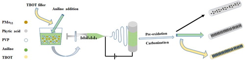
In this work, we provide an aniline-assisted MoP preparation through electrospinning with phytic acid as eco-friendly phosphorous source. Picking Keggin type heteropoly phosphomolybdic acid as starting material and polymerization reaction initiator, the in-situ formed PMo12–PANI precursor facilitated the dispersion of nanoparticles in the final product without severe aggregation, and the synthetic procedure is schematically illustrated in (a). Through addition of tetrabutyl titanate (TBOT), the cycling life and stability were greatly improved. As a result, the carbon nanofiber encapsulated MoP/TiO2 composite maintained around 150 mAh g−1 at 1 A g−1 for 4000 cycles, with superior capacity retention ratio of almost 100%. This work provides a convenient way for the phosphide preparation.
Results and discussion
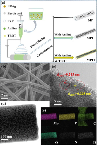
The morphology and microstructure were investigated by SEM and TEM. As shown in Figure (b) and Figure S1a–1b, 1D interconnected nanofibers with diameters around 300–500 nm can be observed in SEM images. Ultrasmall nanoparticles of MP (MoP) were spread over the carbon matrix in Figure S1c, after the addition of aniline, the particles sizes were further reduced and uniformly encapsulated in the carbon nanofiber (MPI, Figure S1d), originated from the dispersion effect of PMo12-PANI precursor [Citation22]. The introduction of titania didn’t change the morphology for MPIT sample (Figure d), and EDX mapping exhibits well-dispersed Mo/P/N/O/C/Ti element, conforming the filler of TBOT (Figure e). The constructed heterostructure interface can be vaguely observed from the marginal part of fiber, which can be assigned to the (200) and (101) planes of TiO2 and MoP respectively [Citation23,Citation24].
Figure 1. (a) Schematic illustration for the preparation of MP, MPI and MPIT, (b) SEM, (c) HRTEM, (d) TEM photo of MPIT, (e) EDX element mapping for MPIT.
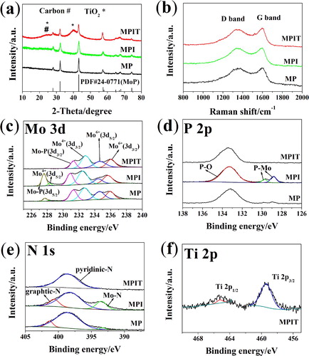
The XRD patterns of MP, MPI and MPIT are presented in Figure (a), the MoP phase was well crystallized in all the three samples. While for MPIT, the broaden peaks around 25° and 40° illustrated the introduction of titania [Citation25,Citation26]. The MoP content was calculated to be 62.50%, 55.60% and 49.94% for MP, MPI and MPIT respectively based on thermogravimertitric analysis (Figure S2), and the ratio of TiO2 is about 10.08%. N2 adsorption and desorption tests (Figure S3) indicated low specific surface area for all three samples (below 10 m2 g−1). Raman peaks (Figure b) around 1350 and 1590 cm−1 can be assigned to D band (induced by defects or disordered structure) and G band (originating from graphitic sp2 carbon) of carbon materials, respectively. After the introduction of aniline, the peak intensity ratio ID/IG increased for MPI (0.98) and MPIT (0.99) compared to MP sample (0.86), implying generation of more defects. XPS spectra were collected to study the surface property and element composition. Mo 3d high-resolution spectrum is presented in Figure (c), and two peaks around 227.6 and 231 eV verified the existence of MoP. The peak at 228.2 eV/232.7 eV and doublets located at 234.6 eV/235.9 eV are assigned to Mo4+ and Mo6+ respectively, illustrating the molybdenum oxides-dominated layers, which is beneficial to the surface faradaic reaction enhancement [Citation8]. Also, the peak with binding energy of 133 eV in P 2p spectrum corresponding to P–O related to surface passivation, while peaks at 129.6 eV/128.8 eV attributed to P 2p3/2 and P 2p1/2 of MoP (Figure d) [Citation9]. In Figure (e), intensified Mo–N peaks can be identified after the aniline addition, conforming the transformation of PMo12-PANI precursor. For MPIT sample, Mo–P and Mo–N related peaks diminished in Mo 3d, P 2p and N 1s spectra, implying nearly complete encapsulation of MoP in the carbon nanofiber matrix with the help of TBOT filler. Relatively weak signal of Ti 2p can be detected in Figure (f), denoting the introduction of TBOT and thus the titanium dioxide formation. Three peaks at 530.8, 532.4, 532.7 eV indicate the binding energies of O–C = O, O–C, O–P respectively, while the peaks around 284.6, 286.3, 288.8 eV are related to O–C = O, C–O, C–C (Figure S4).
Figure 2. (a) XRD patterns, (b) Raman spectra. High-resolution XPS spectra, (c) Mo 3d, (d) P 2p, (e) N 1s. (f) Ti 2p of MPIT.
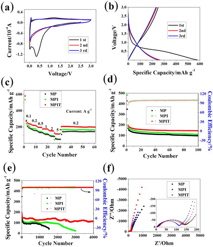
Electrochemical tests for MP, MPI, MPIT were conducted in half-cell in the voltage rage of 0.005–3.0 V (vs. Na/Na+). When tested at 0.1 mV s−1 for three cycles, a distinct reduction peak can be spotted around 0.4 V in the first cathodic scan in Figure (a), corresponding to the solid electrolyte interface film forming process. Peaks located at 0.1 V represent the conversion reaction of MoP to Mo and Na3P [Citation8,Citation11], which is further confirmed by ex-situ XRD tests (Figure S5). In the next two cycles, the curves exhibited well-sustained electrochemical reversibility. The initial charging and discharging curves in Figure (b) explained that the irreversible capacity loss mainly comes from the sodiation process, forming solid electrolyte interface layer while consuming large amount of Na+, which is consistent with the CV curves. And the capacity mostly contributed from the low voltage conversion reaction. The rate capability is presented in Figure (c), the discharging capacity of MPIT sample can be up to 300 mAh g−1 under 100 mA g−1, and keep above 100 mAh g−1 even under current density of 5 A g−1, illustrating the interfacial charge transfer promotion after the heterostructure construction. What’s more, the capacity can retain above 220 mAh g−1 when the current density switched back to 200 mA g−1. In comparison, MP and MPI displayed around 200 mAh g−1 at 100 mA g−1 with relatively poor rate capability. Long-term cycling stability was tested at 1 A g−1 and shown in Figure (e), the MP sample display capacity of 100 mAh g−1 and decayed rapidly after 1000 cycles, while the MPI manifested better performance ascribed to the positive effect of well-dispersed ultrasmall nanoparticle. Surprisingly, the MPIT can retain around 150 mAh g−1 for 4000 cycles with relatively slow fading rate, illustrating the well encapsulation of titania filler, the volume strain got greatly relieved. In Figure (f), electrochemical impedance spectroscopy (EIS) collected at open circuit voltage shows that MoP has a small electrochemical resistance, manifesting its superior electronic conductivity. The resistance reduced for MPI with smaller particle size, while it slightly increased after titania introduction.
Figure 3. Sodium ion storage properties. (a) CV graphs of MPIT at 0.1 mV s−1; (b) initial three galvanostatic charging/discharging curves of MPIT at 100 mA g−1; (c) rate capability tests; (e) cycle performance at 1 A g−1; (d) initial 100 cycles; (f) EIS tests at open circuit voltage.
In Figure , CV curves recorded at a series of scan rate are presented to distinguish the capacitive and diffusion-controlled contribution ratio based on Equation (1) (i represents the current while a and b are variables). The b-value could be derived from the slope of log i versus log v. When b-value approaches 0.5, the diffusion process is dominated, otherwise capacitive process controlled if the b-value is close to 1.0. The numerical values for cathodic and anodic peaks are 0.82 and 0.65 respectively, indicating a surface capacitive-dominated process. Figure (d) exhibits the comparison of capacitive current with the whole current measured. The pseudo-capacitance contributions at sweeping rates of 0.1, 0.3, 0.5, 0.7 and 0.9 mV s−1 are 71.3%, 76.0%, 80.6%, 84.6% and 87.7%, respectively.
(1)
(1)
(2)
(2)
Figure 4. Electrochemical process kinetics analysis for MPIT. (a) CV curves at various sweeping rates from 0.1 to 0.9 mV s−1, (b) corresponding log i versus log v, (c) CV curve with pseudo-capacitance contribution shown by the shaded area at 0.5 mV s−1, (d) bar chart showing the capacitance percentage at different sweep rates, (e) EIS patterns collected after 100, 500, 1000 cycles and (e) corresponding relationship between Z’ and ω−1/2 for MPIT, the slope equals the Warburg coefficient (σw).
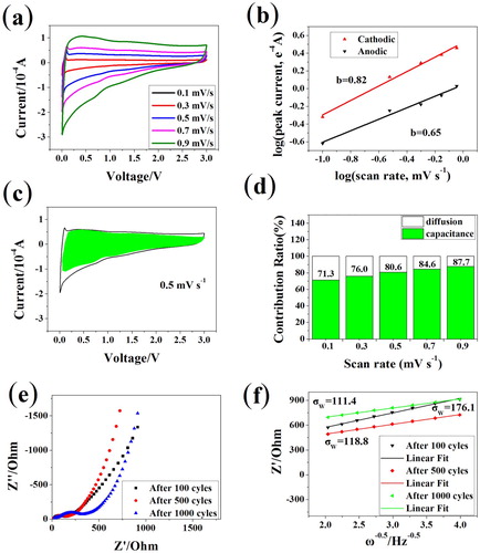
The EIS tests were performed at different cycling stage to study the electrochemical dynamics property of MPIT sample. All the Nyquist spectra in Figure (e) can be divided into a semicircle in the high-medium frequent and a sloping line in the low frequency. The semicircle related to the charge transfer resistance tended to accumulate with cycles. Fitting the low frequency part from Equation (3), we can get the sodium ion diffusion factor related Warburg coefficient (σw), which declined upon initial charging/discharging and remained relatively stable in the subsequent cycles, implying improved diffusion property sustained by carbon fibers confined MoP/TiO2 composite.
(3)
(3)
(4)
(4)
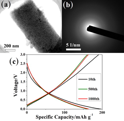
To probe the underlying mechanisms behind the superior cycling durability of MoP/TiO2, the expired electrodes were disassembled for TEM tests. As shown in Figure S6a, the cycled MP sample apparently experienced cracking and pulverization of particles, while the MPI and MPIT specimens almost retained its original morphology, illustrating the smaller particle size can effectively alleviate the stress brought by the volume variations upon cycling. Besides, the selected area electron diffraction (SAED) results (Figure b) confirmed that the active materials also went through an amorphization process, only weak signals can still be detected for the MP (Figure S6b). Due to the interfacial charge transfer promotion of MoP/TiO2 heterostructure, buffering effect of TiO2 and overpotential reducing effect of amorphization [Citation27–29], the polarization during 1 A g−1 cycling was reduced compared to MP and MPI(Figure S6e–6f). Therefore, it’s significant to construct ultrasmall particles confined in nanofibers with heterostructure for the long-term durability.
Figure 5. (a) TEM photos for expired electrode of MPIT, (b) SAED patterns and (c) representative charging-discharging curves at 1 A g−1.
Conclusion
Through electrospinning method with continuous heat treatment, the MoP nanocrystals encapsulated nanofibers were prepared and studied. The addition of aniline and the in-situ formed PMo12-PANI helped to construct carbon matrix confined well-dispersed nanoparticles. The introduction of titania further enhanced the structure stability and greatly alleviated the stress upon cycling. CV and EIS tests proved the enhanced sodium ion storage reaction dynamics. The ex-situ TEM tests combined with charging–charging curves illustrated the improvement for the interfacial charge transfer of titania. In a word, this work provides a convenient method for the construction of phosphide/carbon composites with stable performance. More detailed works can be explored for the further improvement of materials performance.
Impact statement
This work provides a simple and continuous way to fabricate nanofibers confined phosphide nanoparticles from electrospinning method, the as-prepared composites exhibit enhanced electrochemical performance as sodium ion battery anode.
Acknowledgments
This work is supported by the Regional Innovation and Development Joint Fund, National Natural Science Foundation of China (grant number U20A20249), the Science and Technology Program of Guangdong Province of China (grant numbers 2019A050510012, 2020A050515007, 2020A0505090001), the Science and Technology Development Fund, Macau SAR (File no. 0019/2019/AGJ), and by the Guangzhou emerging industry development fund project of Guangzhou development and reform commission.
Disclosure statement
No potential conflict of interest was reported by the author(s).
Additional information
Funding
References
- Sultana I, Rahman MM, Ramireddy T, et al. High capacity potassium-ion battery anodes based on black phosphorus. J Mater Chem A. 2017;5(45):23506–23512.
- Wu X, Leonard DP, Ji X. Emerging non-aqueous potassium-ion batteries: challenges and opportunities. Chem Mater. 2017;29(12):5031–5042. 2017/06/27
- Chang G, Zhao Y, Dong L, et al. A review of phosphorus and phosphides as anode materials for advanced sodium-ion batteries. J Mater Chem A. 2020;8(10):4996–5048.
- Song K, Liu C, Mi L, et al. Recent progress on the alloy-based anode for sodium-ion batteries and potassium-ion batteries. Small. 2021;17(9):e1903194.
- Yu S, Kim S-O, Kim H-S, et al. Computational screening of anode materials for sodium-ion batteries. J Electrochem Soc. 2019;166(10):A1915–A1919.
- Cao Y, Zhang B, Ou X, et al. Facile synthesis of a molybdenum phosphide@carbon nanocomposite as an advanced anode material for sodium-ion batteries. New J Chem. 2019;43(19):7386–7392.
- Huang Z, Hou H, Wang C, et al. Molybdenum phosphide: A conversion-type anode for ultralong-life sodium-ion batteries. Chem Mater. 2017;29(17):7313–7322.
- Jiang Y, Shen Y, Dong J, et al. Surface pseudocapacitive mechanism of molybdenum phosphide for high-energy and high-power sodium-ion capacitors. Adv Energy Mater. 2019;9(27).e1900967.
- Ma C, Deng C, Liao X, et al. Urchin-like MoP nanocrystals embedded in N-doped carbon as high rate lithium Ion battery anode. ACS Appl Energy Mater. 2018;1(12):7140–7145.
- Wang X, Sun P, Qin J, et al. A three-dimensional porous MoP@C hybrid as a high-capacity, long-cycle life anode material for lithium-ion batteries. Nanoscale. 21;8(19):10330–8.
- Yin Y, Fan L, Zhang Y, et al. MoP hollow nanospheres encapsulated in 3D reduced graphene oxide networks as high rate and ultralong cycle performance anodes for sodium-ion batteries. Nanoscale. 11;11(15):7129–7134.
- Hou X, Li W, Wang Y, et al. Sodium-based dual-ion batteries via coupling high-capacity selenium/graphene anode with high-voltage graphite cathode. Chin Chem Lett. 2020;31(9):2314–2318.
- Wang Y-Y, Hou B-H, Guo J-Z, et al. An ultralong lifespan and low-temperature workable sodium-Ion full battery for stationary energy storage. Adv Energy Mater. 2018;8(18).e1900967.
- Wang Y, Liu Y, Liu Y, et al. Recent advances in electrospun electrode materials for sodium-ion batteries. J Energy Chem. 2021;54:225–241.
- Fan S, Wang H, Qian J, et al. Covalently bonded silicon/carbon nanocomposites as cycle-stable anodes for li-ion batteries. ACS Appl Mater Interfaces. 2020 Apr 8;12(14):16411–16416.
- Rehman WU, Wang H, Manj RZA, et al. When silicon materials meet natural sources: opportunities and challenges for low-cost lithium storage. Small. 2021 Mar;17(9):e1904508.
- Zeng F, Yang L, Pan Y, et al. Granular molybdenum dioxide precipitated on N-doped carbon nanorods with multistage architecture for ultralong-life sodium-ion batteries. Electrochim Acta. 2019;325.
- Zeng F, Yu M, Cheng W, et al. Tunable surface selenization on MoO2-based carbon substrate for notably enhanced sodium-ion storage properties. Small. 2020 Oct;16(41):e2001905.
- Li H-H, Saini A, Xu R-Y, et al. Hierarchical Fe3O4@C nanofoams derived from metal–organic frameworks for high-performance lithium storage. Rare Met. 2020;39(9):1072–1081.
- Huang H, Luo X, Yao Y, et al. Binding Se into nitrogen-doped porous carbon nanosheets for high-performance potassium storage. InfoMat. 2021;3(4):421–431.
- Yang Y, Luo M, Xing Y, et al. A universal strategy for intimately coupled carbon nanosheets/MoM nanocrystals (M = P, S, C, and O) hierarchical hollow nanospheres for hydrogen evolution catalysis and sodium-ion storage. Adv Mater. May;30(18):e1706085.
- Cui Z, Guo CX, Yuan W, et al. In situ synthesized heteropoly acid/polyaniline/graphene nanocomposites to simultaneously boost both double layer- and pseudo-capacitance for supercapacitors. Phys Chem Chem Phys. 2012;14(37):12823–12828.
- Zong W, Chui N, Tian Z, et al. Ultrafine MoP nanoparticle splotched nitrogen-doped carbon nanosheets enabling high-performance 3D-printed potassium-ion hybrid capacitors. Adv Sci (Weinh. 2021 Apr;8(7):2004142.
- Huang M, Chu Y, Xi B, et al. TiO2-based heterostructures with different mechanism: a general synergistic effect toward high-performance sodium storage. Small. 2020 Oct;16(42):e2004054.
- Ni M, Sun D, Zhu X, et al. Fluorine triggered surface and lattice regulation in anatase TiO2-xFx nanocrystals for ultrafast pseudocapacitive sodium storage. Small. 2020;16(50):e2006366.
- Luo R, Ma Y, Qu W, et al. High pseudocapacitance boosts ultrafast, high-capacity sodium storage of 3D graphene foam-encapsulated TiO2 architecture. ACS Appl Mater Interfaces. 2020 May 27;12(21):23939–23950.
- Gao M, Cui X, Wang R, et al. Graphene-wrapped mesoporous MnCO3 single crystals synthesized by a dynamic floating electrodeposition method for high performance lithium-ion storage. J Mater Chem A. 2015;3(27):14126–14133.
- Li Q, Liu Z, Wang C, et al. Doping of Ni and Zn elements in MnCO3: high-power anode material for lithium-ion batteries. Small. 2018;14(7).e1900967.
- Guo J, Liu Q, Wang C, et al. Interdispersed amorphous MnOx-carbon nanocomposites with superior electrochemical performance as lithium-storage material. Adv Funct Mater. 2012;22(4):803–811.