
Abstract
Heterogeneous Al–Si microstructure comprising of sub-micron-scale Al dendrites and nanoscale Al–Si fibrous eutectic was fabricated by processing as-cast Al-20wt.%Si alloy using laser rapid solidification. In situ tension tests explored high tensile strength (∼600 MPa) and ductility (∼10%) and high strain hardening rate (∼7 GPa). Microstructural characterization revealed the plastic co-deformation mechanisms between soft Al dendrites and hard nanoscale Al–Si eutectic. The progression of plasticity in nanoscale Al–Si eutectic with increasing applied strain is accommodated by dislocation plasticity in the nano-Al channels and cracking Si nanofibers. The propagation of nano-cracks is suppressed by surrounding Al, retaining good ductility of the sample.
IMPACT STATEMENT
In situ tension tests revealed the role of heterogeneous Al–Si microstructure in enhancing strain hardening rate and producing large back stresses and plasticity in sample even after fracture of nanoscale Si fibers.
GRAPHICAL ABSTRACT
1. Introduction
Cast Al–Si binary alloys are widely used in aerospace and automotive industries due to their low cost, good castability, corrosion and wear resistance [Citation1]. However, the coarse Si flakes cannot effectively improve the strength and ductility of cast Al–Si binary alloys due to brittle fracture of Si flakes [Citation2,Citation3]. Correspondingly, cast Al–Si binary alloys have low strength (<200 MPa) and low tensile ductility (<5%) at room temperature. Refinement of eutectic Si could be an effective way to improve mechanical properties of Al–Si alloys [Citation4,Citation5]. Many strategies have been demonstrated to refine Si phase, such as adding alloy elements during casting [Citation6], changing solidification rate [Citation5,Citation7], severe plastic deformation [Citation3] and friction stir processing [Citation8]. However, the size of Si phase is usually in the micron scale. Lack of slip transmission across the coarse and hard Si limits plastic co-deformation, and consequently, cracks are easily produced in the Si flakes or at Al–Si interfaces [Citation9,Citation10]. Moreover, strength–ductility tradeoff dilemma exists in the modified Al–Si alloys. For example, increased tensile ductility up to ≈25% was obtained in an Al-12wt.%Si alloy by selective laser melting and heat treatment [Citation11], although at a relatively low ultimate tensile strength (UTS) of ≈200 MPa. In hypoeutectic Al-7wt.%Si alloys, using isostatic pressing and high-pressure torsion, the microstructure morphology was changed from dendritic/eutectic to Si nanoprecipitates enhancing yield strength up to ≈400 MPa but no obvious strain hardening [Citation12]. In this manuscript, the focus is on tensile properties of heterogeneous Al–Si dendritic/eutectic microstructure morphology of laser melting nominally hypereutectic compositions.
Heterogeneous structure engineering is an effective strategy to simultaneously improve the strength and ductility of metallic alloys [Citation13,Citation14]. This was attributed to the strong synergistic effect arising from the interaction between soft and hard phases (heterogeneous zones), which is highly dependent on the size, morphology and distribution of heterogeneities [Citation13]. Strain localization such as necking or shear instability can be effectively suppressed by the high strain hardening behavior of heterogeneous microstructure [Citation15]. Although traditional hypoeutectic Al–Si alloys have heterogeneities such as Al dendrites and Al–Si eutectic domain, the synergistic effect between them is weak due to the coarse size of Si. Moreover, crack often preferentially nucleates at the boundary between Al dendrites and Al–Si eutectic [Citation6,Citation9,Citation16]. Herein, we fabricated ultrafine heterogeneous Al–Si microstructure composed of nanoscale Al–Si eutectic and fine Al dendrites by laser rapid solidification (LRS). Compression tests revealed that heterogeneous Al–Si microstructure with primary Si and fibrous eutectic Al–Si had peak flow strength up to ≈600 MPa with compressive plasticity of ≈20% [Citation4]. However, most nanocrystalline and nanocomposite materials exhibit enhanced yield strength but lack tensile ductility even though plasticity could be observed in compression. For nanoscale structures containing hard and brittle phases, it is crucial to determine the tensile stress–strain to avoid ambiguity in inferring ductility from compression tests and to assess plastic deformability between disparate metallic Al and hard Si nano phases. In addition, understanding the relationship between laser melt pool microstructures and tensile properties can guide laser additive manufacturing, since the heterogeneous Al–Si dendritic/eutectic microstructure is controlled by the processing parameters and high thermal gradients during laser melting [Citation17].
2. Experimental methods
In this study, we conducted in situ scanning electron microscope (SEM) tension tests of heterogeneous Al–Si microstructures at room temperature. In situ SEM mechanical testing has been widely used to explore microstructure–properties relations and deformation behaviors of materials [Citation18–22]. The as-cast Al-20wt.%Si specimen was processed by using two different laser scanning speeds: 30 and 60 mm/s, respectively. More detailed preparation and processing methods of specimen could be found in supplementary materials and our previous work [Citation17]. Since the mechanical response of heterogeneous Al–Si microstructure may depend on the local microstructure variation in the melt pool such as area fraction, morphology, orientation and distribution of Al dendrites, small-scale (gauge length of 15 µm, width of 5 µm and thickness of 4.5 µm) tensile samples with constant microstructure were used. Tensile specimens were prepared by focused ion beam (FIB) milling in an FEI (now Thermo Fisher) Helios Nanolab 660 dual-beam SEM. In situ SEM tension tests were conducted using Hysitron (now Bruker) PI85 PicoIndenter with a homemade diamond griper at a strain rate of 10−3 s−1. Transmission electron microscope (TEM) and scanning TEM (STEM) characterization were performed using an FEI (now Thermo Fisher) Tecnai Osiris electron microscope operated at 200 kV. Transmission Kikuchi diffraction (TKD) analysis was performed in the Helios Nanolab 660 dual-beam SEM/FIB. Thin-film samples for TKD and TEM were prepared by the FIB lift-out technique. The statistical analysis (size distribution and area fraction) was accomplished by using Image J software. For the size distribution, at least 150 Al dendrites or Si nanofibers were taken.
3. Results and discussion
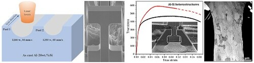
As shown in the schematic (Figure (a)) and SEM images (Figure S1a, Figure S1b), the width and depth of pool 1 (laser scanning speed of 30 mm/s at 1200 W) are 640 and 250 µm, respectively, while the pool 2 (laser scanning speed of 60 mm/s at 1200 W) is smaller with width and depth of 560 and 200 µm, respectively. The as-cast hypereutectic Al-20wt.%Si alloy (Figure (b)) was composed of eutectic region and massive primary Si phase, in which Si present sharp edges and vertices. The average width and inter-flake spacing of Si flakes in the eutectic region are 1.4 and 4.5 µm, respectively. In the laser melt pool, no primary Si was observed and a heterogeneous microstructure developed (Figure (c,d), Figure S2): sub-micron-scale Al dendrites with elliptical shape were embedded in nanoscale Al–Si fibrous eutectic. Note that the distribution of heterogeneous Al–Si microstructure in the same pool is nonuniform due to decreasing cooling rate from top surface to bottom of melt pool, resulting in finer Al dendrites in the top region of the melt pool (Figure S1(c,f)). The average widths of Al dendrites (Figure (e)) in the top region were 0.6 µm in pool 1 and 0.38 µm in pool 2. Si fibers in the eutectic regions were refined to nanoscale and exhibited an average diameter of ≈40 nm (Figure (f)) and an average spacing of ≈30 nm (Figure (g)), respectively. Figure (h,i) is the STEM image and the corresponding inverse pole figure (IPF) of heterogeneous Al–Si microstructure in pool 1, in which only the signal of Al was clearly identified due to the fine size of Si fiber and limited spatial resolution of TKD. It is noted that the Al dendrites and Al matrix of Al–Si eutectic have very close orientation within a local area of about 15 µm (length) × 10 µm (width). Thus, in a micro-tensile sample (Figure (a)) of width 5 µm, the Al dendrites and Al–Si eutectic have nearly the same orientation, and the sample could be regarded as nominally single-crystalline Al with a nonuniform distribution of Si nanofibers (no Si fibers in the Al dendrites).
Figure 1. (a) Schematic of laser scanning parameters; (b) optical image of the as-cast Al-20 wt.%Si alloys; (c) SEM and (d) TEM images of the heterogeneous dendritic Al/eutectic Al–Si microstructure in the melt pool 1; (e–g) statistical distribution of width of Al dendrites (e), Si fiber diameter (f), Si fiber spacing (g); and (h) STEM image and (i) the corresponding inverse pole figure of heterogeneous Al–Si microstructure in pool 1.
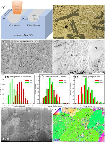
Figure 2. (a) Tensile stress–strain curves and (b) corresponding SEM images of the sample surfaces with increasing tensile strain; (c) Tensile strength and ductility of Al–Si alloys reported in literature compared to the current study; and (d) Strain hardening rates as a function of true plastic strain calculated from stress–strain curves shown in (a).
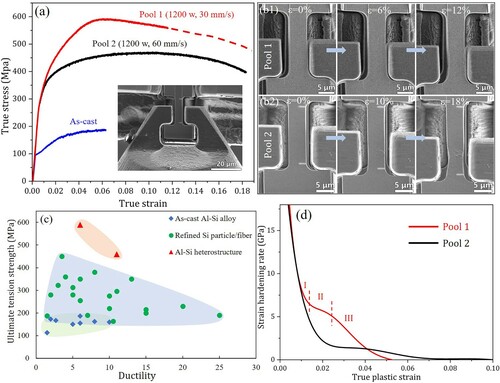
Figure (a,b) shows the tensile true stress—true strain curves and corresponding SEM snapshots of the two heterogeneous Al–Si microstructures (Supplementary Movies). The engineering stress–strain curves of the two samples and one as-cast sample are shown in Figure S3 in supplementary material. The yield strength and ultimate tension stress (UTS) of sample 1 (from melt pool 1) are 450 and 600 MPa, respectively. The UTS corresponds to a tensile strain of 6% above which softening is observed with the development of necking (Figure (b1)). In order to characterize details of deformation in the sample, the loading was stopped at a tensile strain of ≈12%, and the sample was not fractured. It is noticed that cracking or shear instability did not occur, implying good plasticity of heterogeneous Al–Si microstructures. The yield strength and UTS of sample 2 (from melt pool 2) are 350 and 450 MPa, respectively. The UTS corresponds to a tensile strain of 10%, and consequently, softening is associated with necking and later surface cracking at a tensile strain of 18% (Figure (b2)).
Compared to the reported Al–Si alloys [Citation2,Citation3,Citation5,Citation11,Citation12, Citation23–32], Figure (c) shows that the laser rapid solidified heterogeneous Al–Si microstructures exhibit a superior combination of tensile strength and ductility. Figure (d) shows the corresponding strain hardening rate of heterogeneous Al–Si microstructures. Sample 1 exhibits a high strain hardening rate of 7 GPa in the range of plastic strain of 1.5∼2.5%, corresponding to E/10 where E is the Young’s modulus of Al (70 GPa) [Citation33]. Then the strain hardening rate decreases to near zero at a plastic strain of 5.5%. The strain hardening rate of heterogeneous Al–Si microstructures is much higher than the strain hardening (E/50) in bulk fcc single crystals. Unlike sample 1, sample 2 exhibits a lower strain hardening rate, about 2 GPa (E/35) in the range of plastic strain of 2.5∼5%.
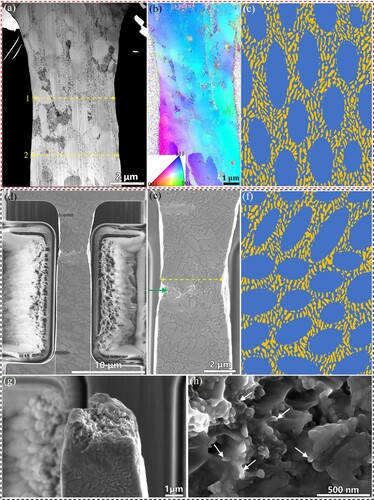
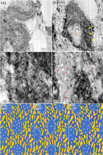
The different stress–strain response of two samples should be related to their microstructures. The bright-field (BF)-STEM image of the necked region in sample 1 (Figure (a)) reveals two features: (i) the Al dendrites and Al–Si eutectics with an elongated shape are alternately distributed along the transverse direction of the sample, and (ii) the long direction is nearly parallel to the loading direction. The average widths of alternately distributed Al dendrites and Al–Si eutectics are about 0.52 µm along the yellow arrow 1, and 0.8 µm along the yellow arrow 2. Although the widths of these Al dendrites and Al–Si eutectics are different, the area fraction of Al dendrites is similar, about 50%. TKD analysis (Figure (b)) does not reveal any significant misorientation between the Al dendrites and the Al matrix in the eutectic after tensile straining, similar to the TKD map prior to the tensile test (Figure (i)). The necked region shows smooth surfaces and no surface cracks as presented in Figure (b1), and shown schematically in Figure (c). Ion beam imaging in SEM was used to characterize the microstructure of sample 2. Figure (d) is the ion-channeling image of sample 2 after a tension strain of 18%. According to the contrast, the white smooth surface is associated with Al dendrites and the gray surface is associated with Al–Si eutectics. Figure (e) is an enlarged SEM image of the necking region. It is noticed that the necking region is corresponding to a high area fraction of Al dendrites, about 75% along the yellow arrow. A surface crack is initiated in Al dendrite. More importantly, the long direction of Al dendrite and Al–Si eutectic is nearly perpendicular to the loading direction, forming a local layer structure. Plastic deformation mainly takes place in the Al dendrite. Correspondingly, the incompatibility of plastic deformation between Al dendrite and Al–Si eutectic facilitates crack initiation in the Al dendrite. Figure (f) shows the schematic microstructure of the necking region in sample 2.
Figure 3. (a) BF STEM image and (b) TKD map of the necked region in sample 1; (c) schematic of the microstructure of the necked region in sample 1; (d) ion-channeling image of sample 2 after a tensile strain of 18%; (e) enlarged view and schematic (f) of microstructure in the necked region in (d); and (g) SEM image and (h) enlarged view of fracture surface, arrows indicate fractured Si nanofibers.
The aforementioned difference in microstructure, the area fraction of Al dendrites about 50% in sample 1 and 75% in sample 2, well accounts for the lower yield stress of sample 2. In addition, the alternate distribution of Al dendrites and Al–Si eutectics across the transverse direction of sample 1 results in uniform plastic deformation in two phases, developing high strain hardening and preventing initiation of surface crack. In contrast, plastic deformation primarily develops in Al dendrite with a low strain hardening rate and surface crack initiates in Al dendrite of sample 2, where Al dendrite and Al–Si eutectic form a local layer structure. The deformation mechanism is discussed further in the following section.
After sample 2 was reloaded to fracture, we characterized its fracture surface. The heterogeneous Al–Si microstructure shows ductile dimpled fracture appearance (Figure (g)). Figure (h) is a representative SEM image of the fracture surface with higher magnification, revealing dimples and pulled-out Si nanofibers. Note that some granular Si ‘particles’ are also visible in the fracture surface. This should be caused by the different observation view of the Si nanofibers because of their relatively irregular morphology and random distribution.
Deformation mechanisms and strain hardening behavior of heterogeneous Al–Si microstructure were analyzed based on TEM characterization of sample 1. Three regions are selected for TEM characterization according to the distance from the necked region. Corresponding to different levels of plastic deformation, region 1 is ≈6 µm away from the necked region marked by the yellow arrow 1 in Figure (a), thus having the smallest plastic deformation; region 2 is about 4 µm away from the necking region; and region 3 is the necked region which should experience the largest deformation. BF-STEM imaging was used to eliminate the dynamical diffraction effect. Figure (a) in region 1 shows a high density of dislocations in the soft Al dendrites, implying that plastic deformation commences in Al dendrites. The nanoscale Al–Si fibrous eutectic should have higher yield strength than Al dendrites because the glide force in the Al matrix is inversely related to the spacing of Si nanofibers based on the confined layer slip model [Citation34]. At the first deformation stage, the hard nanoscale Al–Si eutectic may still be elastically deformed due to the fine spacing of Si nanofibers. Correspondingly, nanoscale Al–Si eutectics act as strong barriers for dislocations in Al dendrites. With increasing applied strain, more dislocations will pile up at the interface between Al dendrites and Al–Si eutectic, developing plastic deformation incompatibility between them and producing a high density of geometrical necessary dislocations (GNDs) as shown in Figure (b). Meanwhile, more load will transfer to Al–Si eutectic. Back stress in the soft zones (Al dendrites) and forward stress in the hard zones (nanoscale Al–Si eutectic) were generated due to the long-range internal stress from GND pileup [Citation13,Citation35]. Back stress offsets the applied stress to impede dislocation motion in the soft zones, making the soft phase stronger. Dislocation strengthening and back-stress hardening in Al dendrites give rise to apparent strain hardening rate (6–7 GPa) at a true strain of 1.5-–2.5% (Segment II in Figure (d)). Forward stress will act as the additional stress to trigger nucleation and glide of dislocation in the hard zones. As presented in Figure (b), dislocations were observed in Al–Si eutectic adjacent to the boundary of Al dendrite. With a further increase in the applied strain, plastic deformation extensively proceeded in the Al–Si eutectic domains. The high density of dislocation arrays confined by Si nanofibers was observed in the Al matrix in Al–Si eutectic as marked by white arrows in Figure (c). In addition, dislocation accumulation was clearly observed in the interface region between Al dendrites and Al–Si eutectic. Si nanofibers deform elastically and act as strong barriers for dislocation motion. Consequently, these dislocations loop and accumulate along Si nanofibers, creating tensile stress along Si fibers and eventually breaking Si fibers to discretize the accumulated dislocations. Note that the cracks in Si nanofibers do not quickly propagate into the Al matrix, as observed in Figure (d). More importantly, failure of Si nanofibers enables continued plastic deformation of Al–Si eutectic domain, achieving plastic co-deformation between Al dendrites and Al–Si eutectic domain, and correspondingly reduced strain hardening rate in the range of plastic strain of 2.5-–5.5% (Segment III in Figure (d)). Figure (d) is a representative TEM image of the Al–Si eutectic in the necking area, showing a high density of fractured Si fibers (marked by red arrows). The formation of white contrast ‘voids’ or ‘holes’ in the necking area should be the result of dropped broken Si nanofibers from the sample during the ion beam milling process.
Figure 4. BF-STEM images showing (a) a high dislocation density in Al dendrite; (b) geometrically necessary dislocation accumulation at the interface region between Al dendrite and Al/Si eutectic; (c) dislocation activity in the nano-Al channels inside the Al/Si eutectic domains; and (d) fractured Si nanofibers. (e)–(g) Schematic illustration of the propagation of plasticity in the heterogeneous Al–Si microstructure with increasing plastic strain from (e) to (f) to (g).
The three plastic deformation stages, with increasing applied strain, of heterogeneous Al–Si microstructure can be rationalized as follows: (1) plastic deformation commences in the soft Al dendrites via dislocation slip, producing large amounts of statistically stored dislocations in the Al dendrites. Al–Si eutectic may elastically deform and act as barriers to form dislocation pileup at the interface between Al dendrites and Al–Si eutectic domains. Strain hardening is enhanced in Al dendrites corresponding to the formation of dislocation pileups. (2) With increasing applied strain, plastic deformation starts in the Al–Si eutectic domain via dislocation slip in the Al matrix of Al–Si eutectic domain. Si nanofibers elastically deform and act as strong barriers for dislocations. Al dendrites and Al–Si eutectic domain achieve plastic co-deformation with a high strain hardening rate. (3) Dislocations in the Al matrix of Al–Si eutectic domain will loop and form arrays along Si nanofibers, creating tensile stress along the fiber. Si nanofibers eventually break, leading to a reduction in strain hardening but it is noted that nano-cracks in Si nanofibers do not propagate in the Al matrix, preventing material failure and achieving continued plastic deformation of the specimen. The corresponding schematic diagram of the three deformation stages is presented in Figure (e–g), respectively.
4. Conclusions
In summary, laser-processed heterogeneous Al–Si microstructure composed of sub-micron-scale Al dendrites and nanoscale Al–Si fibrous eutectic shows high tensile strength and ductility and high strain hardening behavior. The stress–strain response of heterogeneous Al–Si microstructure is highly dependent on its local microstructure, such as area fraction, morphology and distribution of Al dendrites. TEM characterization revealed that the superior mechanical property of heterogeneous Al–Si microstructure is attributed to the strong synergistic effect between relatively ‘soft’ Al dendrites and ‘hard’ Al–Si eutectic.
Supplemental Material
Download Zip (6 MB)Disclosure statement
No potential conflict of interests was reported by the authors.
Additional information
Funding
References
- Hirsch J. Recent development in aluminium for automotive applications. Trans Nonferrous Met Soc China. 2014;24:1995–2002.
- Aktarer SM, Sekban DM, Saray O, et al. Effect of two-pass friction stir processing on the microstructure and mechanical properties of as-cast binary Al–12Si alloy. Mater Sci Eng A. 2015;636:311–319.
- Purcek G, Saray O, Kul O. Microstructural evolution and mechanical properties of severely deformed Al-12Si casting alloy by equal-channel angular extrusion. Met Mater Int. 2010;16:145–154.
- Lien H-H, Mazumder J, Wang J, et al. Ultrahigh strength and plasticity in laser rapid solidified Al–Si nanoscale eutectics. Mater Res Lett. 2020;8:291–298.
- Hosch T, Napolitano RE. The effect of the flake to fiber transition in silicon morphology on the tensile properties of Al–Si eutectic alloys. Mater Sci Eng A. 2010;528:226–232.
- Rao J, Zhang J, Liu R, et al. Modification of eutectic Si and the microstructure in an Al-7Si alloy with barium addition. Mater Sci Eng A. 2018;728:72–79.
- Van Cauwenbergh P, Samaee V, Thijs L, et al. Unravelling the multi-scale structure–property relationship of laser powder bed fusion processed and heat-treated AlSi10Mg. Sci Rep. 2021;1:6423.
- Ma Z, Sharma S, Mishra R. Microstructural modification of as-cast Al-Si-Mg alloy by friction stir processing. Metall Mater Trans A. 2006;37:3323–3336.
- Wang QG. Microstructural effects on the tensile and fracture behavior of aluminum casting alloys A356/357. Metall Mater Trans A. 2003;34:2887–2899.
- Cáceres CH, Davidson CJ, Griffiths JR. The deformation and fracture behaviour of an Al-Si-Mg casting alloy. Mater Sci Eng A. 1995;197:171–179.
- Li XP, Wang XJ, Saunders M, et al. A selective laser melting and solution heat treatment refined Al–12Si alloy with a controllable ultrafine eutectic microstructure and 25% tensile ductility. Acta Mater. 2015;95:74–82.
- Liu M, Zheng R, Xiao W, et al. Bulk nanostructured Al-Si alloy with remarkable improvement in strength and ductility. Scripta Mater. 2021;201:113970.
- Zhu Y, Ameyama K, Anderson PM, et al. Heterostructured materials: superior properties from hetero-zone interaction. Mater Res Lett. 2021;9:1–31.
- Wu X, Zhu Y. Heterogeneous materials: a new class of materials with unprecedented mechanical properties. Mater Res Lett. 2017;5:527–532.
- Wu H, Fan G. An overview of tailoring strain delocalization for strength-ductility synergy. Prog Mater Sci. 2020;113:100675.
- Jiang W, Fan Z, Dai Y, et al. Effects of rare earth elements addition on microstructures, tensile properties and fractography of A357 alloy. Mater Sci Eng A. 2014;597:237–244.
- Lien H-H, Mazumder J, Wang J, et al. Microstructure evolution and high density of nanotwinned ultrafine Si in hypereutectic Al-Si alloy by laser surface remelting. Mater Charact. 2020;161:110147.
- Ma Z, Zhao H, Huang H, et al. A novel tensile device for in situ scanning electron microscope mechanical testing. Exp Tech. 2015;39:3–11.
- Sano T, Yu J, Davis B, et al. In-situ scanning electron microscopy comparison of microstructure and deformation between WE43-F and WE43-T5 magnesium alloys. In: Sillekens WH, Agnew SR, Neelameggham NR, et al., editors. Magnesium technology. Springer; 2011. p. 345–348. doi:https://doi.org/10.1007/978-3-319-48223-1_64.
- Boehlert CJ, Cowen CJ, Tamirisakandala S, et al. In situ scanning electron microscopy observations of tensile deformation in a boron-modified Ti–6Al–4 V alloy. Scripta Mater. 2006;55:465–468.
- Liu Y, Li N, Arul Kumar M, et al. Experimentally quantifying critical stresses associated with basal slip and twinning in magnesium using micropillars. Acta Mater. 2017;135:411–421.
- Xu S, Xie D, Liu G, et al. Quantifying the resistance to dislocation glide in single phase FeCrAl alloy. Int J Plast. 2020;132:102770.
- Pandee P, Gourlay CM, Belyakov SA, et al. Alsi2sc2 intermetallic formation in Al-7Si-0.3Mg-xSc alloys and their effects on as-cast properties. J Alloys Compd. 2018;731:1159–1170.
- Xu C, Wang F, Mudassar H, et al. Effect of Sc and Sr on the eutectic Si morphology and tensile properties of Al-Si-Mg alloy. J Mater Eng Perform. 2017;26:1605–1613.
- Zheng Q, Zhang L, Jiang H, et al. Effect mechanisms of micro-alloying element La on microstructure and mechanical properties of hypoeutectic Al-Si alloys. J Mater Sci Technol. 2020;47:142–151.
- Li Q, Qiu F, Dong B-X, et al. Investigation of the influences of ternary Mg addition on the solidification microstructure and mechanical properties of as-cast Al–10Si alloys. Mater Sci Eng A. 2020;798:140247.
- Kang J, Su R, Wu DY, et al. Synergistic effects of Ce and Mg on the microstructure and tensile properties of Al-7Si-0.3Mg-0.2Fe alloy. J Alloys Compd. 2019;796:267–278.
- Liu W, Xiao W, Xu C, et al. Synergistic effects of Gd and Zr on grain refinement and eutectic Si modification of Al-Si cast alloy. Mater Sci Eng A. 2017;693:93–100.
- Lei W, Liu X, Wang W, et al. On the influences of Li on the microstructure and properties of hypoeutectic Al-7Si alloy. J Alloys Compd. 2017;729:703–709.
- Dang B, Zhang X, Chen YZ, et al. Breaking through the strength-ductility trade-off dilemma in an Al-Si-based casting alloy. Sci Rep. 2016;6:30874.
- Caceres CH, Griffiths JR, Reiner P. The influence of microstructure on the Bauschinger effect in an Al-Si-Mg casting alloy. Acta Mater. 1996;44:15–23.
- Wang QG. Plastic deformation behavior of aluminum casting alloys A356/357. Metall Mater Trans A. 2004;35:2707–2718.
- Wang J, Misra A. Strain hardening in nanolayered thin films. Curr Opin Solid State Mater. 2014;18:19–28.
- Misra A, Hirth JP, Hoagland RG. Length-scale-dependent deformation mechanisms in incoherent metallic multilayered composites. Acta Mater. 2005;53:4817–4824.
- Zhu Y, Wu X. Perspective on hetero-deformation induced (HDI) hardening and back stress. Mater Res Lett. 2019;7:393–398.