
 ?Mathematical formulae have been encoded as MathML and are displayed in this HTML version using MathJax in order to improve their display. Uncheck the box to turn MathJax off. This feature requires Javascript. Click on a formula to zoom.
Abstract
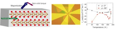
The recent emergence of magnetic van der Waals materials allows for the investigation of current-induced magnetisation manipulation in two-dimensional materials. Uniquely, Fe3GeTe2 has a crystalline structure that allows for the presence of bulk spin–orbit torques (SOTs) that we quantify in a Fe3GeTe2 flake. From the symmetry of the measured torques, we identify current induced effective fields using harmonic analysis and find dominant bulk SOTs arising from the symmetry in the crystal structure. Our results show that Fe3GeTe2 can exhibit bulk SOTs in addition to the conventional interfacial SOTs enabling magnetisation manipulation even in thick flakes without the need for complex multilayer engineering.
GRAPHICAL ABSTRACT
IMPACT STATEMENT
Spin–orbit torques which demonstrates efficient magnetisation switching requires multilayer structures. In FeGe3Te2 van der Waals materials we demonstrate bulk spin–orbit torques in a sole material with possibilities for spintronics applications.
1. Introduction
The discovery of magnetic van der Waals crystals that retain magnetic order in the two-dimensional limit [Citation1–4] opens up the investigation of their magnetic properties and implementation in spintronic devices [Citation5]. Consequently, the efficient control of the magnetic state is essential. Spin–orbit torques (SOTs) provide the opportunity of electrical control of magnetizations [Citation6]. Linking magnetic van der Waals materials with SOTs potentially allows for two-dimensional current induced magnetisation manipulation enabling fast, low power spintronic devices. So far reports of current-induced switching of 2D magnets have been based on interfacial SOTs in complex multilayers requiring small magnetic layer thicknesses, limiting thermal stability [Citation7–9]. One of the promising magnetic van der Waals crystals, Fe3GeTe2, has been shown to exhibit strong perpendicular magnetocrystalline anisotropies [Citation10], tuneable by doping [Citation11] and present even in an atomic monolayer [Citation12]. This, combined with the Dzyaloshinskii-Moriya interaction, also stabilises skyrmions [Citation13–15]. Furthermore, of the van der Waals materials it shows one of the highest bulk Curie temperatures of ∼ 225 K [Citation10,Citation16] which can be increased up to room temperature by ionic gating [Citation17].
While switching due to interfacial spin–orbit torques in Fe3GeTe2 has been studied in multilayer structures, Johansen et al. [Citation18] recently predicted that a possible bulk SOT could be present due to the symmetry of the monolayer crystalline structure. Since Fe3GeTe2 is a metal, the combination of the perpendicular magnetic anisotropy with this theoretically predicted bulk SOTs could potentially enable simple new devices: bulk SOTs are efficient for thick samples that have a better magnetic thermal stability than the thin flakes necessary for interfacial SOTs, while also drastically simplifying single layer device engineering. However, symmetry analysis has so far only indicated bulk SOTs are allowed by symmetry [Citation18], but the torques in single Fe3GeTe2 layers have not been quantified. Although there have been demonstrations of bulk-type SOTs in 3D magnets such as L10 FePt and Co-Tb, the origin and the behaviour of the SOTs are different from the special bulk SOTs that are only present in materials with particular crystalline structure as studied here in Fe3GeTe2 [Citation19,Citation20]. Subsequently there is clear need to check the presence, identify the origin and quantify the amplitude of the torques as key steps forward. In this work, we measure the current induced effective spin–orbit fields in Fe3GeTe2. We analyze the symmetries and amplitudes of the torques to understand the bulk and interfacial contributions to the torques and ascertain the temperature dependence highlighting exceptionally large bulk torques in this system.
2. Results and discussion
Bulk single crystal Fe3GeTe2 was grown by chemical vapour transport (see Supplementary methods). The atomic structure was verified using high-resolution scanning transmission electron microscopy in Figure S1(a) (see also Supplementary Note 1 and 7). We confirmed the stoichiometric composition of the Fe3GeTe2 by energy dispersive X-ray spectroscopy within an error of about 5% (see Supplementary Note 2). Subsequent high-resolution transmission electron microscopy (see Supplementary Note 7) and field and temperature dependence of magnetisation (see Supplementary Notes 8,9) also confirm this. From the grown bulk crystals, Fe3GeTe2 flakes were manually exfoliated and placed on an undoped naturally oxidised silicon substrate. The thickness of the flake was measured with an atomic force microscope (Supplementary Note 10). By using electron beam lithography, gold contacts were fabricated. The final device can be seen in the inset of Figure (a). The flake used in the following study is measured to be 35 nm thick. Assuming the current flows between the transverse contacts, the cross-section area of the investigated flake is estimated to A = 1.75 × 10⁻¹³ m2, which is the value used to calculate the current densities.
Figure 1. (a) Scheme of the 2nd harmonic Hall measurement. An alternating current is injected along the x-direction, while the transverse 1st and 2nd harmonic Hall voltage Utrans is measured via a lock-in amplifier. In the inset an optical microscope image of the final device is depicted. (b) The hysteresis loops of Fe3GeTe2 at different temperatures with the magnetic field applied in the z direction.
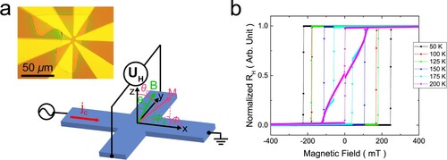
In order to measure the SOTs, higher harmonic Hall measurements [Citation21] are performed. The measurements were done with the configuration shown in Figure (a) where the current was applied in the x direction and the Hall voltage UH was measured in the y direction. The perpendicular magnetic anisotropy of the flake was confirmed by the anomalous Hall measurements for different temperatures as shown in Figure (b). While at low temperature abrupt switching is seen, a multi-step switching appears above 175 K near Tc which shows a formation of domains and even skyrmions as observed by Transmission electron microscopy (TEM) in Figure S4 (supplementary Note 4). At various temperatures and applied alternating currents jC, the first (UH1st) and second harmonic (UH2nd) Hall voltages are recorded using lock-in amplifiers. For each combination of temperature and current, a magnetic field B is applied in the plane to tilt the magnetisation M. Thereby, the external field is either aligned with the longitudinal current direction (ΦB = 0°) or perpendicular to it (ΦB = 90°). A small z-component prevents multi-domain nucleation, so that the polar angle of the external field ranges between 80° ≤ θB ≤ 83°. To take care of heating effects, the second harmonic signal is corrected according to the method outlined in [Citation21].
To extract the SOT effective fields, the measured first and second harmonic voltages were analyzed in supplementary Note 5. In Ref. [Citation18] the current induced effective spin–orbit field has been derived for the Fe3GeTe2 crystal structure:
(1)
(1) Γ0 is a parameter, which represents the strength of the SOTs, JC is the applied current density, mi is the ith component of the magnetisation unit vector and ex and ey are the x- and y-unit vectors. We see that these torques lead to a canting of the spins into the plane of the sample and can facilitate switching by reducing the switching energy barrier. The canting lends itself naturally to detection by higher harmonic Hall measurements. By transforming equation (1) to spherical coordinates and considering the measurement configuration Φ = 0°/90°, we find that the spin–orbit field only comprises a θ-component:
(2)
(2) J0 = j0/A is the current density. For this reason, bΦSOT in equation (S4) is also zero and the first and second harmonic Hall resistances can finally be formulated to:
(3)
(3)
(4)
(4) Consequently, by measuring RH2nd, θ0 and RAHE
=
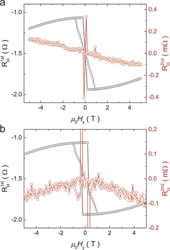
, we derive the current induced effective SOTs bθSOT. In Figure the first and second harmonic Hall resistances after correction for heating effects are plotted as a function of the applied magnetic field when the magnetic field applied in the Φ = 0° and 90° direction. Note that the field dependence of the second harmonic signal in the Φ = 0° and 90° configurations is found to be odd and even, respectively.
Figure 2. Examples of the 1st and 2nd harmonic Hall resistances as a function of the applied magnetic field along the x-direction Φ = 0° (a) and y-direction Φ = 90° (b) at a temperature of 100 K with a polar magnetic field angle of θB = 82°. The applied current density is 4.1 × 10¹⁰ Am−2.
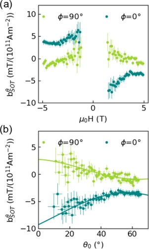
The next step is to check the nature of the torques by measuring their symmetry. To obtain the polar angular dependence (θ0), we plot in Figure (a) the current-induced effective SOT bθSOT as a function of applied magnetic field, corresponding to a certain polar angle. Data points from smaller external fields are omitted, due to the term diverging near the switching region. In Figure (b) the same bθSOT data is plotted as a function of the extracted polar magnetisation angle θ0. To demonstrate the odd-symmetry dependence of the damping-like effective field geometry (Φ = 0°) and check that they overlap, we invert the data points corresponding to negative applied fields. The field-like effective field geometry (Φ = 90°) values range between −2 and 4 mT/1011 Am−2 with the highest values at smaller θ0 angles. The damping-like effective fields decrease in magnitude from −8 to −3 mT/1011 Am−2 with increasing angle. Above θ0 > 45° the absolute value of bθSOT increases again up to −4 mT/1011 Am−2.
Figure 3. The derivative of the θ component of the current induced effective field is shown as a function of the externally applied magnetic field (a) and polar magnetisation angle θ0 (b) at a temperature of 175 K with a polar magnetic field angle of θB = 82°. The applied current density is 3.7 × 10¹⁰ Am−2. In (b) the data for Φ = 0° and negative applied fields has been inverted. The solid lines are fits according to equations (5) and (6).
The key step now is to clarify the origin of these torques to check if they are of bulk origin as predicted. A first observed key feature that allows us to identify the bulk origin is the opposite behaviour of the effective spin–orbit fields for Φ = 0° and Φ = 90° as predicted by equation (2) due to the cos(2Φ) term that yields +1 for Φ = 0° and –1 for Φ = 90°.
Secondly, from the θ0 dependence we identify a dominating bulk origin. We fit equation (2) for pure bulk SOTs to the data in Figure (b). To check if additionally interfacial torques play a role, the fit equation was extended to take into account additional interfacial SOTs [Citation21]. Accordingly, we fit our data with a combination of bulk and interfacial SOTs [Citation18,Citation21]:
(5)
(5)
(6)
(6) Where Ti‖ and Ti⊥ are the ith order components of the longitudinal and transverse components of SOTs from the interface. Figure (b) shows the resulting fit of the interfacial SOTs.
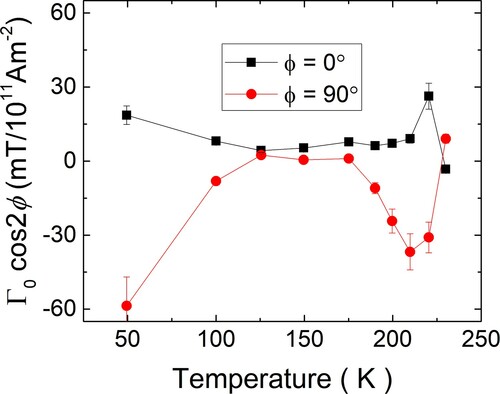
To finally check if the key feature of bulk SOTs, namely the opposite behaviour for Φ = 0° and Φ = 90° is universally present or a random occurrence by chance at 175 K (the data shown in Figure ), we investigate the temperature dependence. By extracting Γ0 from each fit, the fundamental magnitude of bulk SOTs in Fe3GeTe2 can be determined as a function of temperature as shown in Figure . As visible in the temperature dependence, the behaviour of Γ0*cos(2Φ) exhibits consistently at all temperatures opposite behaviour for Φ = 0° and Φ = 90° in line with the prediction for bulk SOTs. Note that the fits for Γ0 were done independently for Φ = 0° and Φ = 90° so that one could easily determine if the temperature dependence were qualitatively different for both orientations. However here we see that for both orientations the largest values for Γ0 occur at the lowest temperatures and then decrease to lower values for temperatures up to 150 K before increasing again and peaking around 215 K. Note that the reduction of Γ0 at even higher temperatures approaching the Curie temperature (230 K) is expected as the magnetic order is lost and at elevated temperature close to the Curie temperature inhomogeneous properties and domain formation can make the analysis less robust. The complex behaviour of Γ0 at elevated temperatures could thus be related to the multi-step switching indicating domain formation shown in Figure (b). We note that at higher temperatures the error bars are smaller as the magnetisation can be tilted with our maximum available vector field of 5 T to higher angles and a wider θ0 angle range can be investigated and fitted since the anisotropy decreases with temperature.
Figure 4. The extracted bulk SOT parameter Γ0*cos(2Φ) as a function of the temperature showing the opposite sign for the Φ = 0° and Φ = 90° data over the full temperature range.
In particular, the data shows that at low temperatures we measure very high values of bθSOT of more than 50 mT/1011 Am−2. Together with the very high interfacial SOTs found in Fe3GeTe2/Pt structures [Citation8,Citation9], this bodes well for efficient switching of the magnetisation in this material by combined bulk and interfacial torques.
In the following, we discuss the possible origins of the SOTs that we measure. In [Citation18] a SOT mechanism related to a broken inversion symmetry of the structure is introduced. While the polar angular dependences found at the different temperatures indicate a dominating bulk origin of the torques, we see that the temperature dependence does show some deviations from the strict proportionality expected from eq. (6) and the absolute values for Φ = 0° and Φ = 90° shown in Figure do not always fully coincide. This indicates that additional higher order torques that can for instance be induced by uniaxial strain can play a role, highlighting the breadth of new torques that can contribute due to our identified bulk mechanisms. Furthermore, we see that fits of the polar angular dependence (Figure ) indicate additional interfacial torques beyond the intrinsic bulk torque can be present. To check why interfacial torques can occur, even though the Fe3GeTe2 device that is measured is in principle a bulk device with a thickness of 35 nm, where no net interfacial torques due to the spin Hall effect or the inverse spin-galvanic effect [Citation6,Citation22] are expected, we consider surface oxidation. Overall, this device has been exposed to air <12 h and literature reports a natural oxidation layer on an exfoliated flake within a time scale of 14 h [Citation23,Citation24,Citation25]. The presence of an oxide layer on the surface exposed to air is confirmed by TEM (see supplementary material figure S3) and thus interfacial SOTs can appear. So we find that in our Fe3GeTe2 device clear evidence for a theoretically reported bulk SOT based on the crystal symmetry breaking [Citation18] and on the other hand an additional interfacial SOT are enabled by local surface oxidation. Mitigation of this surface contribution lies beyond the scope of this paper as either increased sample thickness or complete removal of the oxidation layer are the main options. The first is naturally non-trivial and the second results in drastic sample heating from large current densities. A third possible contribution to the measured SOTs could be Oersted fields, which are additional magnetic fields, which arise due to the current flow and can mimic a field-like torque symmetry. Assuming that the Fe3GeTe2 flake is a homogeneous conductor, the Oersted field is zero in the center of the flake and rises in magnitude at the edges, pointing counterclockwise in the yz-plane [Citation26]. Thus, it points in opposite y-directions at the top and bottom of the flake and cancels to zero. If we assume that the Fe3GeTe2 flake has become a heterogeneous conductor due to possible interfaces, the current flow in the z-direction becomes asymmetric and hence also the Oersted field. In the less conducting areas, this Oersted field can be estimated by HOe = μ0jC/(2πr) according to the Biot-Savart law for an infinite long straight conductor with r the distance from the conductor. Therefore, exactly at the interfaces to less conducting areas e.g. at the top of the flake the Oersted field becomes maximal. However, given that we probe the bulk of the flake, the contribution of the Oersted field will be negligible compared to the measured torque values.
In order to quantify the bulk SOT from a theoretical perspective, we employ the microscopic first-principles framework to compute the anti-damping SOT within the Kubo linear response theory for the Fe3GeTe2 bulk crystal (details are given in the Supplementary Note 6). As bulk Fe3GeTe2 maintains inversion symmetry, the SOT vanishes globally [Citation27]. However, each layer separately exhibits a non-vanishing SOT [Citation28] which may lead to the non-vanishing effect observed experimentally. Instances where inversion symmetry is broken have also been observed [Citation29]. If we decompose the unit cell into the A and B layers of Fe3GeTe2 (Figure S5 of the supporting material) the top and bottom Fe atoms of the A-layer experience an equal in magnitude but opposite in sign SOT for an out-of-plane magnetisation. However, once the magnetisation is tilted away from the out-of-plane direction the SOT for each layer does not cancel out separately. From first principles, the estimated magnitude of the SOT per layer with a magnetisation angle of from the z axis, and
from the current direction of is
and similar order to that found experimentally (Figure (b) at θ0 = 30°, Φ = 55°). A further analysis of the origins of the bulk SOT is presented in supplementary Note 11.
3. Conclusion
In summary, we have measured SOTs in a pure Fe3GeTe2 flake with very large magnitudes of more than 50 mT/1011 Am−2. From a symmetry analysis we can identify the predicted bulk SOTs that result from the particular crystalline structure of the Fe3GeTe2 that we determine by TEM imaging. In addition, we find that additional interfacial SOTs are present that result likely from surface effects such as observed oxidation. Ab initio calculations confirm that the layer resolved bulk SOT is of the same order of magnitude as the experiment. We thus demonstrate that the bulk SOTs that are a unique property of certain van der Waals materials such as Fe3GeTe2 yield very efficient magnetisation manipulation due to high effective fields. The bulk SOTs are independent of the thickness of the material and thus comparatively thick layers with good thermal stability of the magnetic states can be used. Combined with the possibility of simple device design with just a single material without any additional materials and layers, our findings lay the foundations for a new paradigm of 2D materials spin-orbitronic devices.
Supplemental Material
Download MS Word (4.8 MB)Disclosure statement
No potential conflict of interest was reported by the author(s).
Additional information
Funding
References
- Huang B, Clark G, Navarro-Moratalla E, et al. Layer-dependent ferromagnetism in a van Der Waals crystal down to the monolayer limit. Nature. 2017;546(7657):270–273. doi:10.1038/nature22391.
- Gong C, Zhang X. Two-Dimensional magnetic crystals and emergent heterostructure devices. Science. 2019;363(6428):eaav4450, doi:10.1126/science.aav4450.
- Gong C, Li L, Li Z, et al. Discovery of intrinsic ferromagnetism in Two-dimensional van Der Waals crystals. Nature. 2017;546(7657):265–269. doi:10.1038/nature22060.
- Gibertini M, Koperski M, Morpurgo AF, et al. Magnetic 2D materials and heterostructures. Nat Nanotechnol. 2019;14(5):408–419. doi:10.1038/s41565-019-0438-6.
- Wang QH, Bedoya-Pinto A, Blei M, et al. The magnetic genome of Two-dimensional van der Waals materials. ACS Nano. 2022;16:6960–7079.
- Manchon A, Železný J, Miron IM, et al. Current-induced spin-orbit torques in ferromagnetic and antiferromagnetic systems. Rev Mod Phys. 2019;91(3):035004-(1-80), doi:10.1103/RevModPhys.91.035004.
- Ostwal, V., Shen, T., Appenzeller, J. Efficient spin-orbit torque switching of the semiconducting Van Der Waals ferromagnet Cr2Ge2Te6. Adv Mater. 2020, 32 (7), 1906021. doi:10.1002/adma.201906021.
- Alghamdi M, Lohmann M, Li J, et al. Highly efficient spin–orbit torque and switching of layered ferromagnet Fe3GeTe2. Nano Lett. 2019;19(7):4400–4405. doi:10.1021/acs.nanolett.9b01043.
- Wang X, Tang J, Xia X, et al. Current-Driven magnetization switching in a van Der waals ferromagnet Fe3GeTe2. Sci Adv. 2019;5(8):eaaw8904, doi:10.1126/sciadv.aaw8904.
- Verchenko VY, Tsirlin AA, Sobolev AV, et al. Ferromagnetic order, strong magnetocrystalline anisotropy, and magnetocaloric effect in the layered telluride Fe3−δGeTe2. Inorg Chem. 2015;54(17):8598–8607. doi:10.1021/acs.inorgchem.5b01260.
- Park SY, Kim DS, Liu Y, et al. Controlling the magnetic anisotropy of the van der Waals ferromagnet Fe3GeTe2 through hole doping. Nano Lett. 2020;20:95–100.
- Fei Z, Huang B, Malinowski P, et al. Two-Dimensional itinerant ferromagnetism in atomically thin Fe3GeTe2. Nat Mater. 2018;17(9):778–782. doi:10.1038/s41563-018-0149-7.
- Ding B, Li Z, Xu G, et al. Observation of magnetic skyrmion bubbles in a van Der Waals ferromagnet Fe3GeTe2. Nano Lett. 2020;20(2):868–873. doi:10.1021/acs.nanolett.9b03453.
- Wu Y, Zhang S, Zhang J, et al. Néel-Type skyrmion in WTe2/Fe3GeTe2 van Der Waals heterostructure. Nat Commun. 2020;11(1):3860, doi:10.1038/s41467-020-17566-x.
- Park T-E, Peng L, Liang J, et al. Néel-Type skyrmions and their current-induced motion in van Der Waals ferromagnet-based heterostructures. Phys Rev B. 2021;103(10):104410, doi:10.1103/PhysRevB.103.104410.
- León-Brito N, Bauer ED, Ronning F, et al. Magnetic microstructure and magnetic properties of uniaxial itinerant ferromagnet Fe3GeTe2. J Appl Phys. 2016;120(8):83903, doi:10.1063/1.4961592.
- Deng Y, Yu Y, Song Y, et al. Gate-Tunable room-temperature ferromagnetism in Two-dimensional Fe3GeTe2. Nature. 2018;563(7729):94–99. doi:10.1038/s41586-018-0626-9.
- Johansen Ø, Risinggård V, Sudbø A, et al. Current control of magnetism in Two-dimensional Fe3GeTe2. Phys Rev Lett. 2019;122(21):217203, doi:10.1103/PhysRevLett.122.217203.
- Lee JW, Park JY, Yuk JM, et al. Spin-Orbit torque in a perpendicularly magnetized ferrimagnetic Tb-Co single layer. Phys Rev Appl. 2020;13(4):44030, doi:10.1103/PhysRevApplied.13.044030.
- Zheng SQ, Meng KK, Liu QB, et al. Disorder dependent spin–orbit torques in L10 FePt single layer. Appl Phys Lett. 2020;117(24):242403, doi:10.1063/5.0028815.
- Garello K, Miron IM, Avci CO, et al. Symmetry and magnitude of spin–orbit torques in ferromagnetic heterostructures. Nat Nanotechnol. 2013;8(8):587–593. doi:10.1038/nnano.2013.145.
- Manchon, A.; Belabbes, A. Chapter One - spin-orbitronics at transition metal interfaces Vol. 68, In Camley, R. E., Stamps, R. L. B. T.-S. S. P., editors. Cambridge, MA: Academic Press, 2017; pp 1–89. 10.1016/bs.ssp.2017.07.001.
- Kim D, Park S, Lee J, et al. Antiferromagnetic coupling of van Der Waals ferromagnetic Fe3GeTe2. Nanotechnology. 2019;30(24):245701, doi:10.1088/1361-6528/ab0a37.
- Park T-E, Peng L, Liang J, et al. Néel-type skyrmions and their current-induced motion in van Der Waals ferromagnet-based heterostructures. arXiv:1907.01425. July 1, 2019, p arXiv:1907.01425.
- Kim DS, Kee JY, Lee JE, et al. Surface oxidation in a van der Waals ferromagnet Fe3-xGeTe2. Curr Appl Phys. 2021;30:40–45.
- Ho P, Zhang J, Bono DC, et al. Oersted field and spin current effects on magnetic domains in [Co/Pd]15 nanowires. IEEE Trans Magn. 2016;52(6):1–6. doi:10.1109/TMAG.2016.2526972.
- Zhang K, Han S, Lee Y, et al. Gigantic current control of coercive field and magnetic memory based on nanometer-thin ferromagnetic van Der Waals Fe3GeTe2. Adv Mater. 2021;33(4):2004110, doi:10.1002/adma.202004110.
- Saunderson TG, Go D, Blügel S, et al. Hidden interplay of current-induced spin and orbital torques in bulk Fe3GeTe2, arXiv:2204.13052 (2022).
- Chakraborty A, Srivastava AK, Sharma AK, et al. Magnetic skyrmions in a thickness tunable 2D ferromagnet from a defect driven Dzyaloshinskii–Moriya interaction. Adv Mater. 2022;34:2108637.