
 ?Mathematical formulae have been encoded as MathML and are displayed in this HTML version using MathJax in order to improve their display. Uncheck the box to turn MathJax off. This feature requires Javascript. Click on a formula to zoom.
Abstract
Piling-ups of geometrically necessary dislocation (GND) arrays against interfaces are known to produce hetero-deformation induced (HDI) strengthening and strain hardening to enhance the strength and ductility of heterostructured materials. Here we report an interesting dislocation mechanism that can produce strong HDI hardening: consecutive reflections of GND planar piling-up arrays near the opposite phase boundaries in a heterostructured AlCoCrFeNi2 high entropy alloy (HEA). In contrast, dislocation transmission was found at grain boundaries in the fcc phase. The discovery here provides guidance for future materials design, which may improve the combination of strength and ductility of metallic materials.
GRAPHICAL ABSTRACT
IMPACT STATEMENT
A hitherto unknown consecutive reflection of GND arrays near phase boundaries of a heterostructured HEA is observed and proposed as a key contributor to HDI hardening.
Introduction
Since the Bronze Age, metallic materials have served mankind in nearly all aspects of life. The properties of metallic materials can be adjusted by alloying and microstructure engineering, making them one of the most widely used materials today [Citation1]. With exacerbating global warming and the energy crisis, it has become urgent to build energy-efficient transportation vehicles, which demand strong and tough materials [Citation2]. Consequently, new classes of metallic materials such as nanostructured materials [Citation3–6], high entropy alloys (HEAs) [Citation7–12] and heterostructured materials [Citation13–20] have been recently developed due to their outstanding mechanical properties. Heterostructured materials is an emerging and fast-developing materials field, including both structural and functional materials [Citation21–24], because of the new materials science associated with their superior properties and their easy large-scale production using current industrial facilities at low cost [Citation25,Citation26].
Heterostructured materials consist of heterogeneous zones that have dramatic differences in strength(>100%). During their deformation, mechanical interaction between the heterostructured zones produces back stress in the soft zones and forward stress in the hard zones, which collectively produce hetero-deformation induced (HDI) stress, leading to HDI strengthening and strain hardening [Citation27,Citation28]. Specifically, geometrically necessary dislocations (GNDs) from Frank-Read dislocation sources in the soft zone glides on a slip plane and piles up against zone boundaries. This produces back stress in the soft zones to make them appear stronger. The GND pile-ups also exert stress concentrations on the zone boundaries, which consequently induce forward stress in the hard zones. To produce high HDI stress, it is critical to form large numbers of GND pile-ups per unit volume. Higher back stress should lead to higher HDI stress [Citation13].
The hypoeutectic AlCoCrFeNi2 HEA [Citation29] is a type of heterostructured material consisting of the fcc and bcc dual-phase structure [Citation30]. Due to the substantial atomic size mismatch of the constituent elements, strong lattice distortion and thus high lattice friction are realized to increase the dislocation density and to slow down the dislocation speed [Citation31], which substantially improves the chance to capture dislocation-interface interactions via in-situ TEM [Citation32–34]. Here we report an interesting mechanism to produce a high density of GND pile-ups, using the dual-phase AlCoCrFeNi2 HEA as a model material. Specifically, the phase boundaries act as barriers and reflectors to GND pile-ups so that GNDs from a single Frank-Read source can be reflected several times consecutively to produce multiple GND pile-ups, which consequently produces very high HDI strain hardening. The HEA has short range ordering, which promotes planar slip to promote the GNDs pileup against the phase boundaries during the multiple reflection of the GND arrays. A unique type of interaction between GND arrays and the zone boundaries is found. More information can be found in the Supplemental materials.
Results and discussion
Figure (a) shows a dual-phase heterostructure consisting of alternative face-centered cubic (fcc) and body-centered cubic (bcc) lamellae, which was formed after annealing cold-rolled AlCoCrFeNi2 HEA at 1200°C for 1 hour. The volume fraction of the bcc phase is ∼30%. The bcc zone is mainly in green color in the inverse pole figure (IPF) map (Figure (b1)), indicating a strong (101) texture (Supplementary Figure 2), which is consistent with Ref. [Citation30]. The bcc lamellae are mostly single crystals, with an average length ∼9.1 μm and width of ∼2.4 μm (Figure (b2)). In contrast, the fcc grains are equiaxed with random orientations (Figure (b3)). The fcc phase has an average grain size of ∼6.6 μm (Figure (b4)).
Figure 1. Microstructure of the annealed AlCoCrFeNi2 HEA before in-situ tensile deformation. (a) Phase map showing both fcc and bcc lamellae. (b1) and (b3) are inverse pole figures of bcc and fcc phases, respectively. (b2) and (b4) are size distribution of bcc and fcc phases, respectively. and
denote the average width and length of bcc phase, respectively.
denotes the average grain size of fcc phase. (c1) Bright field TEM image showing a typical interphase interface. (c2) and (c3) are selected area diffraction patterns for fcc and bcc phases. (d1) and (d2) are atomic resolution TEM images taken at the same position after tilting for α and β angles.
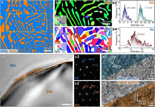
Both the grain and phase boundaries in the sample are strong barriers to dislocation slip. Figure (c1) shows a bright field phase boundary image. Prior to tensile straining, the phase boundary is sharp and clean, and dislocation density is low in the grain interior. Figure (c2) and (c3) show the selected area diffraction patterns at both sides of the phase boundary, indicating an upper fcc grain and a lower bcc grain. Figure (d1) and (d2) show the high-resolution transmission electron microscopy (HRTEM) images of the same area. During TEM observations, the upper fcc crystal was firstly tilted to the [110] zone axis (Figure (d1)). Later, the lower grain was tilted to the [111] zone axis (Figure (d2)). The angle between the [110] orientation of the fcc grain and the [111] orientation of the bcc grain can then be estimated as ∼11°. There is no specific orientational relationship between fcc and bcc phases. The phase boundary is considered an incoherent interface.
In-situ TEM can provide direct observation of dynamic interactions between GNDs and the phase boundary, as well as the evolution of the GND pile-up arrays during deformation [Citation34–37]. Figure (a1) to (a3) are snapshots from Supplementary Video 1 showing dislocation slip in the interior of an fcc grain. Sluggish GND slip (Dislocations I and II, marked by the green arrows) confined in a planar array is observed. According to Refs. [Citation38–40], the collective trapping effect of the ‘cocktail solid solution' [Citation41], in conjunction with the massive pile-up of dislocations, slows down the motion of GNDs. Meanwhile, the dislocation III (marked by the yellow arrow) outside of the planar array stays stationary, suggesting a confined slip in certain slip planes.
Figure 2. Dislocation activities in fcc grain interior of the AlCoCrFeNi2 HEA. (a1)–(a3) Serial in-situ TEM images from Supplementary Video 1 showing the motion of dislocations confined in a slip plane. (b1)–(b3) Screenshots from Supplementary Video 2 showing a dislocation marked by V cross-slip from a primary (11) plane onto an intersecting (1
1) plane. (c1)–(c3) Sequential snapshots of extensive cross-slip processes when two planar arrays interact with each other. See Supplementary Video 3 for further details.
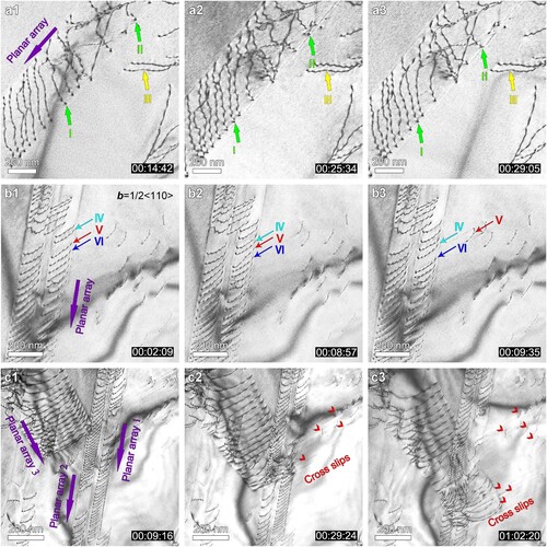
TEM observations under different two-beam conditions confirmed the Burgers vectors of the dislocations in Figure as <110 > . As shown in Figure (b1), three dislocations, IV, V and VI, initially glide in a planar array on a (11
) plane. With increasingly applied strain, the dislocation V gradually comes to a standstill, then suddenly cross-slips onto the (1
1) slip plane and leaves a track which slowly fades away, while the adjacent dislocations IV and VI remain on the original slip plane (Figure (b2) and (b3), snapshots from Supplementary Video 2).
Figure (c1) to (c3) are sequential snapshots showing dislocation entanglements and interactions at the intersections of planar arrays. As shown in Supplementary Video 3, planar array 3 firstly approaches and collides onto planar array 2. The array 2 is then affected by both the strain fields of arrays 1 and 3. As a result, dislocations in the array 2 tangle with incoming dislocations of the array 3 to form a dislocation network containing dislocations of different Burgers vectors. As the array 3 extends forward, additional stress is imposed by its strain field to dislocations in the array 1. There is sufficient free space on the right side of the array 1. Thus, many dislocations (marked by the red arrows) in the array 1 cross-slip onto (11) planes to the right of the figure, under the resultant stress from arrays 1 and 3. Entanglements and interactions of planar arrays are deemed to contribute to superior strain hardening [Citation42].
Phase boundaries are major obstacles to dislocation slip in dual-phase materials, playing a dominant role in strain partitioning and HDI strengthening. Here in-situ TEM observation reveals a unique dislocation interaction with phase boundaries. Figure (a1) is a low magnification TEM image showing dislocation interactions with phase boundaries. The dislocation slip path exhibits a zig-zag trace in the fcc phase, as marked by the green and turquoise dash lines. Figure (a2) to (a6) are close-up snapshots from Supplementary Video 4, showing the slip path development. The slip path 1 is strictly confined on {111} slip planes (Figure (a1)), dislocation slip along path 1 to reach the phase boundary (Figure (a2)). As plastic deformation proceeds, GNDs pile up in an array against the phase boundary, building up a local stress concentration. Eventually, the resultant local stress drives the dislocations to cross slip to an intercepting {111} plane at the phase boundary. Consecutive cross slip of the GND arrays at the interface extends the path of dislocation slip to a new direction. Each time the dislocation path encounters the phase boundary, cross slip can occur. The process can be repeated several times to eventually form the zig-zag slip path, as shown in Figure (a1). It is worth noting that the phase boundary is neither totally straight nor exactly parallel to the Burgers vector of the dislocations. Thus, the incoming screw dislocation has to re-align its dislocation line near the interface prior to cross slip.
Figure 3. Interactions between dislocations and two types of boundaries in the AlCoCrFeNi2 HEA. (a1) Low magnification bright field image, showing dislocation-phase boundary interactions. (a2)–(a6) Serial snapshots from Supplementary Video 4, showing dislocations ‘reflection' by phase boundaries. (b1)–(b3) Serial snapshots from Supplementary Video 5 showing the dislocations-GB interactions.
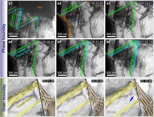
The zig-zag slip path 1 resembles in some way a reflection phenomenon. The phase boundary ‘reflects' incoming dislocations like a mirror, except that the reflection paths need to be on slip planes. As shown in Figure (a4) to (a6), the slip path 2 develops in the same way as slip path 1. Slip paths 1 and 2 are parallel and ‘reflected' at the same angle by the phase boundary, thus slip path 1 intersects with slip path 2 at the positions marked by the red dots after ‘reflection’ in this particular case (Figure (a5)). Although dislocations in paths 1 and 2 may interact at the intersection, they can eventually break away and continue to glide on their original paths. The dislocation reflection phenomenon has been captured by in-situ and post-mortem TEM (Supplementary Figure 3), and in both TEM samples and bulk samples, indicating the universality of this phenomenon.
The fcc grains are within the size range of 2–15 μm. In this grain size range, the CRSS for dislocation slip would not change much in magnitude, despite of the varied shapes of grains. Therefore, the GND reflection mechanism can be operative in all fcc grains, if the local stress reaches a critical value (Supplementary Figure 3). However, the GND reflection mechanism is a dislocation slip based mechanism, it must be affected by the grain size effect. If the grain size is too small e.g. in the ultrafine grained regime or even smaller, the CRSS for dislocation slip will be very high [Citation5,Citation43], and the mean free path for dislocation slip will be too small, then the GND reflection mechanism shall theoretically cease to operate. In coarse grains with sizes of a few hundred micrometers or larger, there would be many Frank-Read sources emitting dislocations simultaneously under plastic deformation. In this case, dislocations from many different sources would interact and tangle before reaching grain boundaries, thus the chance for GND reflection would be very much limited.
GND interactions with conventional grain boundaries (GBs) are different from that with phase boundaries. Figure (b1) to (b3) are sequential snapshots from Supplementary Video 5. Figure (b1) shows three parallel GND arrays encountering a GB, building up local stress concentration. As the leading dislocation approaches the GB, contrast at the GB darkens due to stress-induced strain field (Figure (b2)). When the leading dislocation reaches the position approximately 100 nm to the GB, the leading dislocation is suddenly absorbed by the GB at the stress concentration site, at the same time dislocations are emitted on both sides of the GB. Although dislocation lines on the other side of the GB are not very clear due to grain misorientation, our video (Supplementary Video 5) still captured the moment when a curved dislocation segment (marked by a brown arrow) with pinned ends expanding and eventually bowing out to glide on a new slip plane (colored brown in Figure (b3)). The reaction between the incipient dislocation array and the GB can activate a grain boundary source to emit new dislocations on the other side of the GB [Citation44–46]. Such a dislocation reaction typically leaves behind a residual dislocation at the GB. Several residual dislocations may recombine to emit a new dislocation into the original grain as indicated by the blue arrow in Figure (b3).
Figure (a) shows the tensile true stress-strain curve of the annealed AlCoCrFeNi2 HEA sample. The heterostructure contributes significantly to the observed excellent strain hardening. Strain partitioning between bcc and fcc phases promotes the HDI hardening [Citation14] on top of the conventional forest dislocation hardening [Citation47]. The HDI stress caused by GNDs and the effective stress caused by forest dislocation hardening can be calculated [Citation14,Citation27,Citation48]:
(1)
(1)
(2)
(2) where σHDI, σflow, σeff, σu and σr are the HDI stress, flow stress, effective stress, unloading yield stress and reloading yield stress, respectively. In practice, the HDI hardening effect is manifested by the stress-strain hysteresis loops in load-unload-reload (LUR) tensile tests [Citation14,Citation48]. Typical stress-strain hysteresis loops are shown in Figure (a) and (b). The σr and σu can be directly measured from the hysteresis loops.
Figure 4. Mechanical properties of dual-phase AlCoCrFeNi2 HEA. (a) True stress-strain curves obtained by monotonic and loading-unloading tensile tests. (b) Enlarged unloading-reloading hysteresis loops taken from a part of a. c σHDI, σflow and σHDI/σflow against tensile strain.
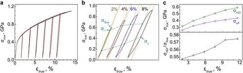
Evolutions of σHDI, σeff and σHDI/σflow with applied strain are plotted in Figure (c). Both the HDI and effective stresses increase with increasing strain. Note that the HDI stress increases faster than the effective stress. As a result, the ratio σHDI/σflow also increases with the increasing strain. Apparently, σHDI contributes more than 50% of the flow stress at all strain levels, indicating the importance of the HDI stress in the plastic deformation.
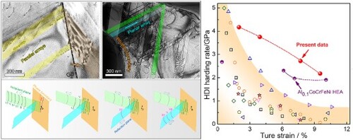
Figure (a) shows multiple reflections of GND pile-up arrays at phase boundaries, which produces multiple GND pile-ups to effectively improve HDI strain hardening. As shown in Figure (c), the HDI stress continues to increase with increasing applied strain. This long-lasting HDI strain hardening is in sharp contrast with those of many other heterostructured materials [Citation13,Citation48] (Supplementary Figure 4 and the discussion on HDI strengthening in the Supplementary materials). The HDI stress usually quickly increases with applied strain and then approaches a saturation in heterostructured materials, because when both the soft zones and hard zones are deforming plastically, the forward stress acts to soften the hard zone, which offsets the back stress hardening in the soft zones.
The strategy of multiple reflections of GND arrays has several advantages over the GND pile-ups observed in other heterostructured materials. First, it is capable to produce multiple GND pile-ups from one Frank-Read dislocation source, which multiplies the HDI stress per unit volume. Second, this strategy also distributes the stress concentration points more uniformly to avoid breaching the zone boundary by a single pile-up of GNDs. In other words, if all GNDs in a zig-zag pile-up shown in Figure line up in one slip plane, the stress concentration at the pile-up head might be high enough to activate dislocations in the hard zone, or possibly initiate a crack. Third, the multiple reflections of GND arrays avoided the absorption of GNDs by the zone boundaries, as reported earlier [Citation49]. Once GNDs are absorbed by zone boundaries, they will no longer produce back stress. The continuous GND absorption by zone boundaries is one of the reasons for the ineffective HDI strengthening observed in the brass-copper layer structure [Citation50].
Pronounced cross slip in the grain interiors helps to release the local stress concentrations (Figure (c1) to (c3)), contributing to the plasticity, but to little effect of HDI hardening. GNDs pile up against conventional GBs is necessary for accommodating non-homogeneous plastic strains between grains of varied orientations [Citation51]. Adjacent grains in the same phase have the same shear modulus, thus the GB is incapable of sustaining a too-high stress concentration imposed by the GNDs pile-up. Instead, GNDs will be absorbed by the GB, and subsequently a GB source will be activated to emit new dislocations in the adjacent grain or back to the original grain but in another slip system, as shown in Figure (b1) to (b3). As a result, GNDs pile-up at GBs can induce some degree of HDI stress similar to many polycrystalline materials, but apparently the HDI stress (Bauschinger effect) is very limited [Citation52,Citation53]. In contrast, a zone boundary can sustain a much higher stress concentration than a conventional GB. This is because a much higher stress is needed to emit new dislocations in the adjacent zone with a higher shear modulus (Koehler effect) [Citation54] or significantly smaller grains (Hall-Petch effect) [Citation55]. As a result, dislocations and plastic strains are contained in the soft zones by the zone boundaries, stimulating significant HDI stresses [Citation14].
It is of scientific importance to understand how the GND arrays cross-slip at the zone boundaries. The simplest scenario is when the zone boundary is parallel to the GND Burgers vector. Since the GNDs become pure screw dislocations when they reach the zone boundary, they can cross-slip easily without creating any residual dislocations at the zone boundary, which allows continuous cross-slip. However, this is the ideal case that can rarely occur for the reflection of GND arrays. The real situation of GND array reflections in most cases is more complex.
It can be rationalized that most GND array reflections occur at zone boundaries that are not parallel to the Burgers vector. In such a scenario, the cross-slip at the zone boundary becomes impossible because once a dislocation line lies on the zone boundary, it becomes a mixed dislocation, which cannot cross-slip. The GND can cross-slip only when its dislocation line is parallel to its Burgers vector. Based on the in-situ TEM observations, we propose a mechanism that governs dislocation cross-slip near zone boundaries. As shown in Figure (a1), an array of GNDs glide toward a zone boundary on an incipient slip plane, and reached the zone boundary, but cannot cross-slip because the zone boundary and the Burgers vectors have an angle of θ (Figure (a2)). The following GNDs may also become mixed dislocations and stay on the incipient slip plane. These GNDs exert an expelling force to incoming GNDs. As more GNDs are pushing forward, a GND (GND IV in Figure (a3)) may experience enough driving force to align a segment of its dislocation line parallel to its Burgers vector and thus to enable cross-slip onto the reflection plane (Figure (b1)). With continuous alignment of the dislocation line, the whole GND IV can cross-slip onto the reflection plane afterward (Figure (b2)). As such, the GND can cross-slip gradually from one segment first and then the whole dislocation line follows to accomplish the cross-slip [Citation56,Citation57]. This scenario is energetically easier and statistically more probable than aligning the whole dislocation line to transform it into a pure screw dislocation before cross-slipping. After the cross-slip of the first GND, other following GNDs cross-slip in the same way, leading to the reflection of the GND array (Figure (a4)).
Figure 5. GND reflection mechanism at zone boundaries. (a1)–(a4) Schematic diagrams of an array of dislocations numbered as I, II, III, VI, V and VI reflecting at a zone boundary. (b1) and (b2) Close-up diagrams showing a detailed cross-slip process of GND IV. (c) and(d) Bright field TEM images showing the evidence of piling-up and reflection of GNDs at a distance from the zone boundary.
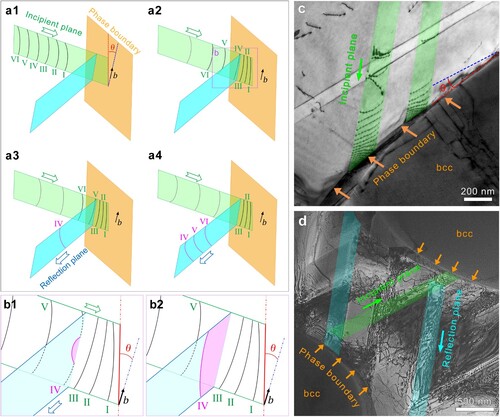
In the above cross-slip mechanism, the reflection of GND arrays occurs at a short distance from the zone boundary. This was indeed observed in the TEM observation. As shown in Figure (c), a GND segment in the left green path is straightened to align parallel with its Burgers vector prior to cross slip, as marked by the blue line, which is where incipient and reflection plane meet for the cross slip to proceed (Figure (d)). Hence, the actual cross-slip location is slightly away from the zone boundary. A few dislocations are also seen between the cross-slip location and the zone boundaries. These dislocations are curved and unable to cross slip, but they provide a buffer layer that makes it possible for the following GNDs to adjust their orientation for cross-slip (Figure (c)). Therefore, these GNDs between the cross-slip location and the zone boundary can be considered as ‘cushion' dislocations. This also increases dislocation density near the zone boundaries. Note that, there could be some geometrical issues to affect the reflection trace of planar arrays. Suppose the initial array slips in a (111) plane. If the θ is an acute or obtuse angle to the initial array, the cross slip could happen on different slip planes, such as the (11) or (11
) planes. Additionally, the incident planar array may even be perpendicular to the phase boundary. In this particular case, the reflection of the dislocation array may be restrained. However, based on the EBSD result in Figure , it has been demonstrated that there is no specific orientation relationship between the BCC and FCC phases. Thus, such a particular case could not to be dominated in the alloy.
For an individual GND pileup, cross-slip limits the local stress concentration and number of GNDs in the pile-up. The global HDI stress measured experimentally is related to the number of GND pileups multiplied by the average number of GNDs per pileup per unit volume. In other words, the global HDI stress is related to the total number of GNDs per unit volume. The GND reflection mechanism observed here produce many GND pileups from a single Frank-Read source; A reflected GND array is actually an extension of the initial GND array emitted from a Frank-Read source. Hence a few Frank-Read sources can produce a large number of GND arrays under the GND reflection mechanism, to effectively enhance the global HDI strengthening and hardening. In addition, as mentioned above, a sufficient high driving force is needed to re-align the Burgers vectors of the dislocations for cross-slip. This driving force needs to be provided by the applied stress, which provides further hardening. In other words, there is additional hardening related to the cross-slip process.
Therefore, it is desired to design alloy compositions and heterostructures to promote this mechanism. The following factors should significantly affect the operation of the multiple reflection of GND arrays. First, planar slip is a prerequisite for this mechanism to operate. It is known that low stacking fault energy (SFE) promotes planar slip [Citation3,Citation4]. However, if the SFE is too low, it also promotes twinning, which could complicate or even disrupt the multiple reflection of the GND arrays. Therefore, the alloy composition should be such that it promotes the planar slip, but not twinning. In other words, the twinning fault energy should be very high in the generalized planar fault energy (GPFE) curve, which can be calculated using density-functional theory (DFT) [Citation58,Citation59]. In addition, high lattice frictional force also promotes planar slip [Citation60]. The AlCoCrFeNi2 HEA in this study meets all these compositional requirements [Citation30,Citation61].
The second factor is the strength difference across the zone boundary. The higher the strength difference, the harder it is for the GNDs to transmit across the zone boundary. The strengths of the zones can be affected by microstructures and textures [Citation28]. The strength differences by differences in dislocation density, precipitation, solution hardening, grain size, etc. [Citation43]. Texture may affect the resolved stresses on dislocation slip systems. If both soft and hard zones are textured in a way that the easy slip systems of both zones are aligned with a low misorientation angle, the chance for dislocation transmission across zone boundaries will be high [Citation62], which lowers the probability for GND array reflection. In the current case, the hard zones are bcc phase with strong (101) texture, but the soft zones are fcc phase with randomly oriented grains. Therefore, the slip systems of the bcc grains are in most cases oriented away from the
slip systems of the fcc grains at the zone boundaries, as shown in Figure (b3, d1, d2). This is one of the reasons that causes pronounced reflection of GND arrays and thus effective HDI strengthening effect.
Summary
In summary, an interesting mechanism involving multiple GND array reflection in the soft zone is found effective in producing HDI strain hardening to maintain good ductility. The GND reflection can be at the zone boundary if it is parallel to the GND Burgers vector, but otherwise it likely occurs at a distance from the zone boundary. There may be high density of cushioning dislocations between the reflection site and the zone boundary. The factors that promote multiple GND array reflection include low stacking fault energy, short-range order of solute atoms, solute atom clustering, and high strength difference across the phase boundaries. These findings provide basic guidance for designing alloys and heterostructures to employ this mechanism for superior strength and ductility.
Supplemental Material
Download Zip (145.3 MB)Disclosure statement
No potential conflict of interest was reported by the author(s).
Additional information
Funding
References
- Han SZ, Choi EA, Lim SH, et al. Alloy design strategies to increase strength and its trade-offs together. Prog Mater Sci. 2021;117:100720.
- Raabe D, Tasan CC, Olivetti EA. Strategies for improving the sustainability of structural metals. Nature. 2019;575:64–74.
- Gleiter H. Nanostructured materials: basic concepts and microstructure. Acta Mater. 2000;48:1–29.
- Meyers MA, Mishra A, Benson DJ. Mechanical properties of nanocrystalline materials. Prog Mate Sci. 2006;51(4):427–556.
- Zhu YT, Liao XZ, Wu XL. Deformation twinning in nanocrystalline materials. Prog Mater Sci. 2012;57(1):1–62.
- Ovid’ko IA, Valiev RZ, Zhu YT. Review on superior strength and enhanced ductility of metallic nanomaterials. Prog Mater Sci. 2018;94:462–540.
- Chen XF, Wang Q, Cheng ZY, et al. Direct observation of chemical short-range order in a medium-entropy alloy. Nature. 2021;592:712–716.
- Yeh JW, Chen SK, Lin SJ, et al. Nanostructured high-entropy alloys with multiple principal elements: novel alloy design concepts and outcomes. Adv Eng Mater. 2004;6(5):299–303.
- Miracle DB, Senkov ON. A critical review of high entropy alloys and related concepts. Acta Mater. 2017;122:448–511.
- Gludovatz B, Hohenwarter A, Catoor D, et al. A fracture-resistant high-entropy alloy for cryogenic applications. Science. 2014;345(6201):1153–1158.
- Li ZM, Pradeep KG, Deng Y, et al. Metastable high-entropy dual-phase alloys overcome the strength–ductility trade-off. Nature. 2016;534:227–230.
- Gludovatz B, Hohenwarter A, Thurston KVS, et al. Exceptional damage-tolerance of a medium-entropy alloy CrCoNi at cryogenic temperatures. Nat Commun. 2016;7:10602.
- Zhu YT, Ameyama K, Anderson PM, et al. Heterostructured materials: superior properties from hetero-zone interaction. Mater Res Lett. 2021;9(1):1–31.
- Zhu YT, Wu XL. Perspective on hetero-deformation induced (HDI) hardening and back stress. Mater Res Lett. 2019;7(10):393–398.
- Wu XL, Zhu YT. Heterogeneous materials: a new class of materials with unprecedented mechanical properties. Mater Res Lett. 2017;5(8):527–532.
- Ma E, Zhu T. Towards strength–ductility synergy through the design of heterogeneous nanostructures in metals. Mater Today. 2017;20(6):323–331.
- Yang MX, Yan DS, Yuan FP, et al. Dynamically reinforced heterogeneous grain structure prolongs ductility in a medium-entropy alloy with gigapascal yield strength. Proc Natl Acad Sci USA. 2018;115(28):7224–7229.
- Du XH, Li WP, Chang HT, et al. Dual heterogeneous structures lead to ultrahigh strength and uniform ductility in a Co-Cr-Ni medium-entropy alloy. Nat Commun. 2020;11:2390.
- Ma E, Wu XL. Tailoring heterogeneities in high-entropy alloys to promote strength–ductility synergy. Nat Commun. 2019;10:5623.
- Wu XL, Jiang P, Chen L, et al. Extraordinary strain hardening by gradient structure. Proc Natl Acad Sci USA. 2014;111:7197–7201.
- Estrin Y, Beygelzimer Y, Kulagin R, et al. Architecturing materials at mesoscale: some current trends. Mater Res Lett. 2021;9(10):399–421.
- Huang GW, Li XH, Lou L, et al. Engineering bulk, layered, multicomponent nanostructures with high energy density. Small. 2018;14(22):1800619.
- Li HL, Li XH, Guo DF, et al. Three-dimensional self-assembly of core/shell-like nanostructures for high-performance nanocomposite permanent magnets. Nano Lett. 2016;16(9):5631–5638.
- Lou L, Li YQ, Li XH, et al. Directional magnetization reversal enables ultrahigh energy density in gradient nanostructures. Adv Mater. 2021;33(36):2102800.
- Gao B, Lai QQ, Cao Y, et al. Ultrastrong low-carbon nanosteel produced by heterostructure and interstitial mediated warm rolling. Sci Adv. 2020;6(39):eaba8169.
- Gao B, Hu R, Pan ZY, et al. Strengthening and ductilization of laminate dual-phase steels with high martensite content. J Mater Sci Technol. 2021;65:29–37.
- Yang MX, Pan Y, Yuan FP, et al. Back stress strengthening and strain hardening in gradient structure. Mater Res Lett. 2016;4(3):145–151.
- Liu YF, Cao Y, Mao QZ, et al. Critical microstructures and defects in heterostructured materials and their effects on mechanical properties. Acta Mater. 2020;189:129–144.
- Lu YP, Gao XZ, Jiang L, et al. Directly cast bulk eutectic and near-eutectic high entropy alloys with balanced strength and ductility in a wide temperature range. Acta Mater. 2017;124:143–150.
- Gao XZ, Lu YP, Zhang B, et al. Microstructural origins of high strength and high ductility in an AlCoCrFeNi2.1 eutectic high-entropy alloy. Acta Mater. 2017;141:59–66.
- Li QJ, Sheng H, Ma E. Strengthening in multi-principal element alloys with local-chemical-order roughened dislocation pathways. Nat Commun. 2019;10:3563.
- Sun SD, Li DW, Yang CP, et al. Direct atomic-scale observation of ultrasmall Ag nanowires that exhibit fcc, bcc, and hcp structures under bending. Phys Rev Lett. 2022;128(1):015701.
- Wang LH, Zhang Y, Zeng Z, et al. Tracking the sliding of grain boundaries at the atomic scale. Science. 2022;375(6586):1261–1265.
- Zhang ZJ, Mao MM, Wang JW, et al. Nanoscale origins of the damage tolerance of the high-entropy alloy CrMnFeCoNi. Nat Commun. 2015;6:10143.
- Wang LH, Teng J, Liu P, et al. Grain rotation mediated by grain boundary dislocations in nanocrystalline platinum. Nat Commun. 2014;5:4402.
- Wang LH, Du K, Yang CP, et al. In situ atomic-scale observation of grain size and twin thickness effect limit in twin-structural nanocrystalline platinum. Nat Commun. 2020;11:1167.
- Liu JB, Chen CX, Xu YQ, et al. Deformation twinning behaviors of the low stacking fault energy high-entropy alloy: An in-situ TEM study. Scripta Mater. 2017;137:9–12.
- Ding QQ, Zhang Y, Chen X, et al. Tuning element distribution, structure and properties by composition in high-entropy alloys. Nature. 2019;574:223–227.
- Wu ZG, Gao YF, Bei HB. Thermal activation mechanisms and labusch-type strengthening analysis for a family of high-entropy and equiatomic solid-solution alloys. Acta Mater. 2016;120:108–119.
- Cao BX, Wang C, Yang T, et al. Cocktail effects in understanding the stability and properties of face-centered-cubic high-entropy alloys at ambient and cryogenic temperatures. Scripta Mater. 2020;187:250–255.
- Ma E. Unusual dislocation behavior in high-entropy alloys. Scripta Mater. 2020;181:127–133.
- Kim SD, Park JY, Park SJ, et al. Direct observation of dislocation plasticity in high-Mn lightweight steel by in-situ TEM. Sci Rep. 2019;9:15171.
- Cao Y, Ni S, Liao XZ, et al. Structural evolutions of metallic materials processed by severe plastic deformation. Mater Sci Eng R. 2018;133:1–59.
- Li JCM. Petch relation and grain boundary sources. Trans Metall Soc AIME. 1963;227:239–247.
- Li JCM, Feng CR, Rath BB. Emission of dislocations from grain boundaries and its role in nanomaterials. Crystals. 2021;11(1):41.
- Essmann U, Wilkens RM. The dislocation arrangement in cold-worked polycrystalline copper rods. Acta Metall. 1968;16(10):1275–1287.
- Madec R, Devincre B, Kubin LP. From dislocation junctions to forest hardening. Phys Rev Lett. 2002;89(25):255508.
- Wang YF, Huang CX, Fang XT, et al. Hetero-deformation induced (HDI) hardening does not increase linearly with strain gradient. Scripta Mater. 2020;174:19–23.
- Zhou H, Huang CX, Sha XC, et al. In-situ observation of dislocation dynamics near heterostructured interfaces. Mater Res Lett. 2019;7(9):376–382.
- Huang CX, Wang YF, Ma XL, et al. Interface affected zone for optimal strength and ductility in heterogeneous laminate. Mater Today. 2018;21(7):713–719.
- Ashby MF. The deformation of plastically non-homogeneous materials. Philos Mag. 1970;21(170):399.
- Moan GD, Embury JD. A study of the bauschinger effect in Al-Cu alloys. Acta Metall. 1979;27(5):903–914.
- Fang H, Horstemeyer MF, Baskes MI, et al. Atomistic simulations of bauschinger effects of metals with high angle and low angle grain boundaries. Comput Method Appl M. 2004;193(17-20):1789–1802.
- Hoagland RG, Mitchell TE, Hirth JP, et al. On the strengthening effects of interfaces in multilayer fee metallic composites. Philos Mag A. 2002;82(4):643–664.
- Hansen N. Hall–petch relation and boundary strengthening. Scripta Mater. 2004;51(8):801–806.
- Hull D, Bacon DJ. Introduction to dislocations. 5th ed. Elsevier Ltd; 2011. 48–50.
- Wu ZX, Curtin WA. Mechanism and energetics of < c + a > dislocation cross-slip in hcp metals. Proc Natl Acad Sci USA. 2016;113(40):11137–11142.
- Jin ZH, Dunham ST, Gleiter H, et al. A universal scaling of planar fault energy barriers in face-centered cubic metals. Scripta Mater. 2011;64:605–608.
- Ding J, Yu Q, Asta M, et al. Tunable stacking fault energies by tailoring local chemical order in CrCoNi medium-entropy alloys. Proc Natl Acad Sci USA. 2018;115(36):8919–8924.
- Hong SI, Laird C. Mechanisms of slip mode modification in F.C.C. solid-solutions. Acta Metall Mater. 1990;38(8):1581–1594.
- Xiong T, Yang WF, Zheng SJ, et al. Faceted Kurdjumov-Sachs interface-induced slip continuity in the eutectic high-entropy alloy, AlCoCrFeNi2.1. J Mater Sci Technol. 2021;65:216–227.
- Seal JR, Crimp MA, Bieler TR, et al. Analysis of slip transfer and deformation behavior across the α/β interface in Ti–5Al–2.5 Sn (wt. %) with an Equiaxed Microstructure. Mater Sci Eng A. 2012;552:61–68.